Page 9 of 110

1-1
EAU00021
QGIVE SAFETY THE RIGHT OF WAYSafety information
1Motorcycles are fascinating vehicles, which can give you an unsurpassed feeling of power and free-
dom. However, they also impose certain limits, which you must accept; even the best motorcycle
does not ignore the laws of physics.
Regular care and maintenance are essential for preserving value and operating condition of your
motorcycle. Moreover, what is true for the motorcycle is also true for the rider: good performance
depends on being in good shape. Riding under the influence of medication, drugs and alcohol is, of
course, out of the question. Motorcycle riders—more than car drivers—must always be at their mental
and physical best. Under the influence of even small amounts of alcohol, there is a tendency to take
dangerous risks.
Protective clothing is as essential for the motorcycle rider as seat belts are for car drivers and passen-
gers. Always wear a complete motorcycle suit (whether made of leather or tear-resistant synthetic
materials with protectors), sturdy boots, motorcycle gloves and a properly fitting helmet. Optimum pro-
tective wear, however, should not encourage carelessness. Although full-coverage helmets and suits,
in particular, create an illusion of total safety and protection, motorcyclists will always be vulnerable.
Riders who lack critical self-control run the risk of going too fast and are apt to take chances. This is
even more dangerous in wet weather. The good motorcyclist rides safely, predictably and defensive-
ly—avoiding all dangers, including those caused by others.
Enjoy your ride!
5PS-28199-E1 8/29/02 9:16 AM Page 8
Page 10 of 110
DESCRIPTION
Left view ............................................................................................2-1
Right view ..........................................................................................2-2
Controls and instruments ...................................................................2-3
2
5PS-28199-E1 8/29/02 9:16 AM Page 9
Page 11 of 110
2-1
EAU00026
DESCRIPTIONPart locations
2
1. Front fork spring preload adjusting bolt (page 3-15)
2. Front fork damping force adjusting
screw (page 3-15)
3. Air filter element (page 6-16)
4. Shock absorber assembly compression
damping force adjusting knob (page 3-17)
5. Battery (page 6-33)
6. Fuses (page 6-34)
7. Storage compartment (page 3-14)8. Grab bar
9. Luggage strap holders (page 3-18)
10. Seat lock (page 3-13)
11. Shock absorber assembly rebound
damping force adjusting knob (page 3-17)
12. Shock absorber assembly spring
preload adjusting ring (page 3-16)
13. Shift pedal (page 3-9)
14. Engine oil drain bolt A (page 6-9)
12
345678
9 9 10 11 12 13 1412
345678
9 9 10 11 12 13 14Left view
5PS-28199-E1 8/29/02 9:16 AM Page 10
Page 12 of 110
2-2
DESCRIPTION
2
15. Tool kit (page 6-1)
16. Coolant reservoir (page 6-11)
17. Throttle stop screw (page 6-17)
18. Front brake master cylinder (page 6-25)
19. Radiator cap (page 6-13)20. Engine oil filler cap (page 6-8)
21. Engine oil filter element (page 6-10)
22. Engine oil drain bolt B (page 6-10)
23. Brake pedal (page 3-10)
24. Rear brake fluid reservoir (page 6-26)
915 16 17 18
19
20 21 22 23 249Right view
5PS-28199-E1 8/29/02 9:16 AM Page 11
Page 13 of 110
2-3
DESCRIPTION
2
1. Clutch lever (page 3-9)
2. Left handlebar switches (page 3-7)
3. Speedometer unit (page 3-4)
4. Main switch/steering lock (page 3-1)
5. Tachometer unit (page 3-5)6. Coolant temperature gauge (page 3-6)
7. Right handlebar switches (page 3-8)
8. Brake lever (page 3-9)
9. Throttle grip (page 6-18)
1 2 345 6 7 8 9
Controls and instruments
5PS-28199-E1 8/29/02 9:16 AM Page 12
Page 14 of 110

INSTRUMENT AND CONTROL FUNCTIONS
Main switch/steering lock ...................................................................3-1
Indicator and warning lights ...............................................................3-2
Speedometer unit ..............................................................................3-4
Tachometer unit .................................................................................3-5
Coolant temperature gauge ...............................................................3-6
Anti-theft alarm (optional) ..................................................................3-7
Handlebar switches ...........................................................................3-7
Clutch lever ........................................................................................3-9
Shift pedal ..........................................................................................3-9
Brake lever ........................................................................................3-9
Brake pedal .....................................................................................3-10
Fuel tank cap ...................................................................................3-10
Fuel ..................................................................................................3-11
Fuel tank breather hose ...................................................................3-12
Catalytic converter ...........................................................................3-12
Seat .................................................................................................3-13
Storage compartment ......................................................................3-14
Adjusting the front fork .....................................................................3-14
Adjusting the shock absorber assembly ..........................................3-16
Luggage strap holders .....................................................................3-18
Sidestand .........................................................................................3-18
Ignition circuit cut-off system ...........................................................3-19
3
5PS-28199-E1 8/29/02 9:16 AM Page 13
Page 15 of 110

3-1
EAU00029
Main switch/steering lockMain switch/steering lockThe main switch/steering lock con-
trols the ignition and lighting systems,
and is used to lock the steering. The
various positions are described
below.
EAU04926
ON
All electrical circuits are supplied with
power; the meter lighting, taillight and
auxiliary light come on, and the
engine can be started. The key can-
not be removed.
EAU00027
INSTRUMENT AND CONTROL FUNCTIONS
3
NOTE:
The headlight comes on automatical-
ly when the engine is started and
stays on until the key is turned to
“OFF”.
EAU00038
OFF
All electrical systems are off. The key
can be removed.
EAU00040
LOCK
The steering is locked, and all electri-
cal systems are off. The key can be
removed.
To lock the steering
1. Turn the handlebars all the way
to the left.
2. Push the key in from the “OFF”
position, and then turn it to
“LOCK” while still pushing it.
3. Remove the key.
To unlock the steering
Push the key in, and then turn it to
“OFF” while still pushing it.
5PS-28199-E1 8/29/02 9:16 AM Page 14
Page 16 of 110

3-2
INSTRUMENT AND CONTROL FUNCTIONS
3
EW000016
w
Never turn the key to “OFF” or
“LOCK” while the motorcycle is
moving, otherwise the electrical
systems will be switched off,
which may result in loss of control
or an accident. Make sure that the
motorcycle is stopped before turn-
ing the key to “OFF” or “LOCK”.
ab
a. Push.
b. Turn.
EAU03034
Indicator and warning lights
Indicator and warning lightsEAU04478
Fuel level warning symbol “”Fuel level warning symbolThis fuel level warning symbol starts
flashing when the fuel level drops
below approximately 3.5 L.
1. Fuel level warning symbol “ ”
2. Left turn signal indicator light “
4”
3. High beam indicator light “&”
4. Neutral indicator light “N”
5. Engine trouble indicator light “ ”
6. Right turn signal indicator light “6”
7. Oil level warning light “
7”
EAU01590
.(Parking)
The steering is locked, and the tail-
light and auxiliary light are on, but all
other electrical systems are off. The
key can be removed.
The steering must be locked before
the key can be turned to “
.”.ECA00043
cC
Do not use the parking position for
an extended length of time, other-
wise the battery may discharge.
5PS-28199-E1 8/29/02 9:16 AM Page 15
 1
1 2
2 3
3 4
4 5
5 6
6 7
7 8
8 9
9 10
10 11
11 12
12 13
13 14
14 15
15 16
16 17
17 18
18 19
19 20
20 21
21 22
22 23
23 24
24 25
25 26
26 27
27 28
28 29
29 30
30 31
31 32
32 33
33 34
34 35
35 36
36 37
37 38
38 39
39 40
40 41
41 42
42 43
43 44
44 45
45 46
46 47
47 48
48 49
49 50
50 51
51 52
52 53
53 54
54 55
55 56
56 57
57 58
58 59
59 60
60 61
61 62
62 63
63 64
64 65
65 66
66 67
67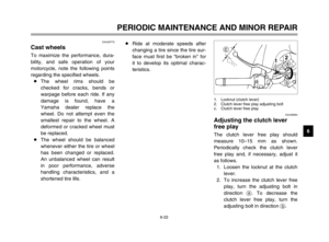 68
68 69
69 70
70 71
71 72
72 73
73 74
74 75
75 76
76 77
77 78
78 79
79 80
80 81
81 82
82 83
83 84
84 85
85 86
86 87
87 88
88 89
89 90
90 91
91 92
92 93
93 94
94 95
95 96
96 97
97 98
98 99
99 100
100 101
101 102
102 103
103 104
104 105
105 106
106 107
107 108
108 109
109

2. Front fork damping force adjusting
screw (page 3-15)
3. Air filter element (page 6-16)
4. Shock abso")

16. Coolant reservoir (page 6-11)
17. Throttle stop screw (page 6-17)
18. Front brake master cylinder (page 6-25)
19. Radiator cap (page 6-13)20. Engine oil")

2. Left handlebar switches (page 3-7)
3. Speedometer unit (page 3-4)
4. Main switch/steering lock (page 3-1)
5. Tachometer unit (page 3-5)6. Coolant tempe")