Page 25 of 110

3-11
INSTRUMENT AND CONTROL FUNCTIONS
32. Turn the key counterclockwise to
the original position, remove it,
and then close the lock cover.
NOTE:
The fuel tank cap cannot be closed
unless the key is in the lock. In addi-
tion, the key cannot be removed if the
cap is not properly closed and
locked.
EWA00025
w
Make sure that the fuel tank cap is
properly closed before riding.
EAU03753
FuelFuelMake sure that there is sufficient fuel
in the tank. Fill the fuel tank to the
bottom of the filler tube as shown.
EW000130
w
8Do not overfill the fuel tank,
otherwise it may overflow
when the fuel warms up and
expands.
8Avoid spilling fuel on the hot
engine.
1 2
1. Fuel tank filler tube
2. Fuel level
EAU00185
cC
Immediately wipe off spilled fuel
with a clean, dry, soft cloth, since
fuel may deteriorate painted sur-
faces or plastic parts.
EAU04284
Recommended fuel:
REGULAR UNLEADED
GASOLINE ONLY
Fuel tank capacity:
Total amount:
20 L
Reserve amount:
3.5 L
5PS-28199-E1 8/29/02 9:16 AM Page 24
Page 26 of 110

3-12
INSTRUMENT AND CONTROL FUNCTIONS
3
ECA00104
cC
Use only unleaded gasoline. The
use of leaded gasoline will cause
severe damage to internal engine
parts, such as the valves and pis-
ton rings, as well as to the exhaust
system.
Your Yamaha engine has been
designed to use regular unleaded
gasoline with a research octane num-
ber of 91 or higher. If knocking (or
pinging) occurs, use a gasoline of a
different brand or premium unleaded
fuel. Use of unleaded fuel will extend
spark plug life and reduce mainte-
nance costs.EAU02955
Fuel tank breather hoseFuel tank breather hoseBefore operating the motorcycle:
8Check the fuel tank breather
hose connection.
8Check the fuel tank breather
hose for cracks or damage, and
replace it if damaged.
8Make sure that the end of the
fuel tank breather hose is not
blocked, and clean it if neces-
sary.
1. Fuel tank breather hose
EAU04960
Catalytic converterCatalytic converterThis motorcycle is equipped with a
catalytic converter in the muffler.
EW000128
w
The exhaust system is hot after
operation. Make sure that the
exhaust system has cooled down
before doing any maintenance
work.
5PS-28199-E1 8/29/02 9:16 AM Page 25
Page 27 of 110
3-13
INSTRUMENT AND CONTROL FUNCTIONS
3
EC000114
cC
The following precautions must be
observed to prevent a fire hazard
or other damages.
8Use only unleaded gasoline.
The use of leaded gasoline will
cause unrepairable damage to
the catalytic converter.
8Never park the motorcycle
near possible fire hazards
such as grass or other materi-
als that easily burn.
8Do not allow the engine to idle
too long.
EAU02925
Seat
SeatTo remove the seat
Insert the key into the seat lock, turn
it counterclockwise, and then pull the
seat off.
1 a
1. Seat lock
a. Unlock.
To install the seat
Insert the projections on the front of
the seat into the seat holder, push
the rear of the seat down to lock it in
place, and then remove the key.
NOTE:
Make sure that the seat is properly
secured before riding.
1. Projection (×2)
2. Seat holder (×2)
5PS-28199-E1 8/29/02 9:16 AM Page 26
Page 28 of 110
3-14
INSTRUMENT AND CONTROL FUNCTIONS
3
EAU04292
Storage compartmentStorage compartmentThis storage compartment is
designed to hold an optional genuine
Yamaha U-LOCK. (Other locks may
not fit.) When placing a U-LOCK in
the storage compartment, securely
fasten it with the straps. When the U-
LOCK is not in the storage compart-
ment, be sure to secure the straps to
prevent losing them.
1. U-LOCK (optional)
2. Strap
When storing the owner’s manual or
other documents in the storage com-
partment, be sure to wrap them in a
plastic bag so that they will not get
wet. When washing the motorcycle,
be careful not to let any water enter
the storage compartment.EAU04929
Adjusting the front forkFront fork, adjustingThis front fork is equipped with spring
preload adjusting bolts and damping
force adjusting screws.
EW000035
w
Always adjust both fork legs
equally, otherwise poor handling
and loss of stability may result.
5PS-28199-E1 8/29/02 9:16 AM Page 27
Page 29 of 110
3-15
INSTRUMENT AND CONTROL FUNCTIONS
3
Spring preload
To increase the spring preload and
thereby harden the suspension, turn
the adjusting bolt on each fork leg in
direction a. To decrease the spring
preload and thereby soften the sus-
pension, turn the adjusting bolt on
each fork leg in direction b.
1
ab
1. Spring preload adjusting bolt
NOTE:
Align the appropriate groove on the
adjusting mechanism with the top of
the front fork cap bolt.
Setting
Minimum (soft) 8
Standard 7
Maximum (hard) 1
231
7654321
8
1. Standard setting
2. Current setting
3. Front fork cap bolt
Damping force
1. Turn the adjusting screw on each
fork leg in direction auntil the
screw moves almost a 1/2 turn
without clicking.
2. Continue turning the adjusting
screw in direction auntil it
clicks. This is the minimum set-
ting.
1. Damping force adjusting screw
5PS-28199-E1 8/29/02 9:16 AM Page 28
Page 30 of 110

3-16
INSTRUMENT AND CONTROL FUNCTIONS
3 3. To increase the damping force,
continue turning the adjusting
screw in direction a. The third
click after the minimum setting is
the maximum setting. If the
adjusting screw is turned further
in direction a, it will move half a
turn before returning to the mini-
mum setting.
NOTE:
Make sure that the adjusting screw is
turned to one of the four settings.
Setting
Minimum (soft) 1
Standard 2
Maximum (hard) 4
EAU04930
Adjusting the shock
absorber assembly
Shock absorber assembly, adjustingThis shock absorber assembly is
equipped with a spring preload
adjusting ring and rebound and com-
pression damping force adjusting
knobs.
EC000015
cC
Never attempt to turn an adjusting
mechanism beyond the maximum
or minimum settings.Spring preload
To increase the spring preload and
thereby harden the suspension, turn
the adjusting ring in direction a. To
decrease the spring preload and
thereby soften the suspension, turn
the adjusting ring in direction b.
1. Spring preload adjusting ring
2. Special wrench
3. Position indicator
Setting
Minimum (soft) 1
Standard 5
Maximum (hard) 9
5PS-28199-E1 8/29/02 9:16 AM Page 29
Page 31 of 110

3-17
INSTRUMENT AND CONTROL FUNCTIONS
3
Rebound damping force
To increase the rebound damping
force and thereby harden the
rebound damping, turn the adjusting
knob in direction a. To decrease the
rebound damping force and thereby
soften the rebound damping, turn the
adjusting knob in direction b.
1. Rebound damping force adjusting knob
Minimum (soft) 20 clicks in direction b*
Standard 12 clicks in direction b*
Maximum (hard) 3 clicks in direction b*
* With the adjusting knob fully turned in direction a
Compression damping force
To increase the compression damp-
ing force and thereby harden the
compression damping, turn the
adjusting knob in direction a. To
decrease the compression damping
force and thereby soften the com-
pression damping, turn the adjusting
knob in direction b.
1. Compression damping force adjusting
knob
Minimum (soft) 12 clicks in direction b*
Standard 11 clicks in direction b*
Maximum (hard) 1 clicks in direction b*
* With the adjusting knob fully turned in direction a
NOTE:
Although the total number of clicks of
a damping force adjusting mecha-
nism may not exactly match the
above specifications due to small dif-
ferences in production, the actual
number of clicks always represents
the entire adjusting range. To obtain
a precise adjustment, it would be
advisable to check the number of
clicks of each damping force adjust-
ing mechanism and to modify the
specifications as necessary.
5PS-28199-E1 8/29/02 9:16 AM Page 30
Page 32 of 110

3-18
INSTRUMENT AND CONTROL FUNCTIONS
3
EAU00315
w
This shock absorber contains
highly pressurized nitrogen gas.
For proper handling, read and
understand the following informa-
tion before handling the shock
absorber. The manufacturer can-
not be held responsible for proper-
ty damage or personal injury that
may result from improper han-
dling.
8Do not tamper with or attempt
to open the gas cylinder.
8Do not subject the shock
absorber to an open flame or
other high heat sources, other-
wise it may explode due to
excessive gas pressure.
8Do not deform or damage the
gas cylinder in any way, as
this will result in poor damp-
ing performance.
8Always have a Yamaha dealer
service the shock absorber.
EAU00324
Luggage strap holdersLuggage strap holdersThere are four luggage strap holders
below the passenger seat, two of
which can be turned out for easier
access.
1. Luggage strap holder (×4)
EAU00330
SidestandSidestandThe sidestand is located on the left
side of the frame. Raise the side-
stand or lower it with your foot while
holding the motorcycle upright.
NOTE:
The built-in sidestand switch is part of
the ignition circuit cut-off system,
which cuts the ignition in certain situ-
ations. (See further down for an
explanation of the ignition circuit cut-
off system.)
5PS-28199-E1 8/29/02 9:16 AM Page 31
 1
1 2
2 3
3 4
4 5
5 6
6 7
7 8
8 9
9 10
10 11
11 12
12 13
13 14
14 15
15 16
16 17
17 18
18 19
19 20
20 21
21 22
22 23
23 24
24 25
25 26
26 27
27 28
28 29
29 30
30 31
31 32
32 33
33 34
34 35
35 36
36 37
37 38
38 39
39 40
40 41
41 42
42 43
43 44
44 45
45 46
46 47
47 48
48 49
49 50
50 51
51 52
52 53
53 54
54 55
55 56
56 57
57 58
58 59
59 60
60 61
61 62
62 63
63 64
64 65
65 66
66 67
67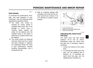 68
68 69
69 70
70 71
71 72
72 73
73 74
74 75
75 76
76 77
77 78
78 79
79 80
80 81
81 82
82 83
83 84
84 85
85 86
86 87
87 88
88 89
89 90
90 91
91 92
92 93
93 94
94 95
95 96
96 97
97 98
98 99
99 100
100 101
101 102
102 103
103 104
104 105
105 106
106 107
107 108
108 109
109
 When p")
