Page 90 of 2234
01±40
±
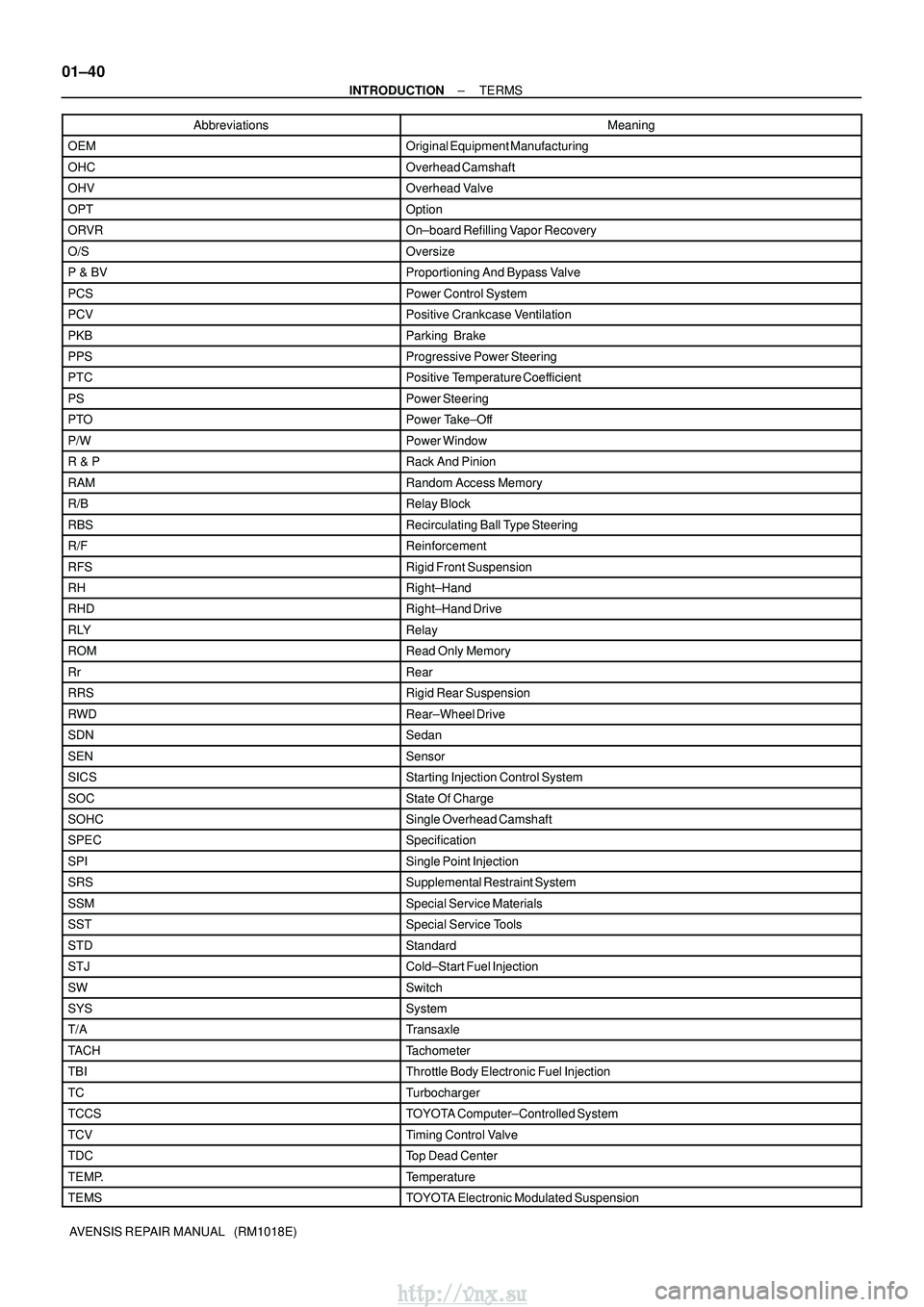
INTRODUCTION TERMS
AVENSIS REPAIR MANUAL (RM1018E) Abbreviations Meaning
OEMOriginal Equipment Manufacturing
OHCOverhead Camshaft
OHVOverhead Valve
OPTOption
ORVROn±board Refilling Vapor Recovery
O/SOversize
P & BVProportioning And Bypass Valve
PCSPower Control System
PCVPositive Crankcase Ventilation
PKBParking Brake
PPSProgressive Power Steering
PTCPositive Temperature Coefficient
PSPower Steering
PTOPower Take±Off
P/WPower Window
R & PRack And Pinion
RAMRandom Access Memory
R/BRelay Block
RBSRecirculating Ball Type Steering
R/FReinforcement
RFSRigid Front Suspension
RHRight±Hand
RHDRight±Hand Drive
RLYRelay
ROMRead Only Memory
RrRear
RRSRigid Rear Suspension
RWDRear±Wheel Drive
SDNSedan
SENSensor
SICSStarting Injection Control System
SOCState Of Charge
SOHCSingle Overhead Camshaft
SPECSpecification
SPISingle Point Injection
SRSSupplemental Restraint System
SSMSpecial Service Materials
SSTSpecial Service Tools
STDStandard
STJCold±Start Fuel Injection
SWSwitch
SYSSystem
T/ATransaxle
TACHTachometer
TBIThrottle Body Electronic Fuel Injection
TCTurbocharger
TCCSTOYOTA Computer±Controlled System
TCVTiming Control Valve
TDCTop Dead Center
TEMP.Temperature
TEMSTOYOTA Electronic Modulated Suspension
http://vnx.su
Page 111 of 2234
02±32
±
PREPARATION DRIVE SHAFT / PROPELLER SHAFT
AVENSIS REPAIR MANUAL (RM1018E)
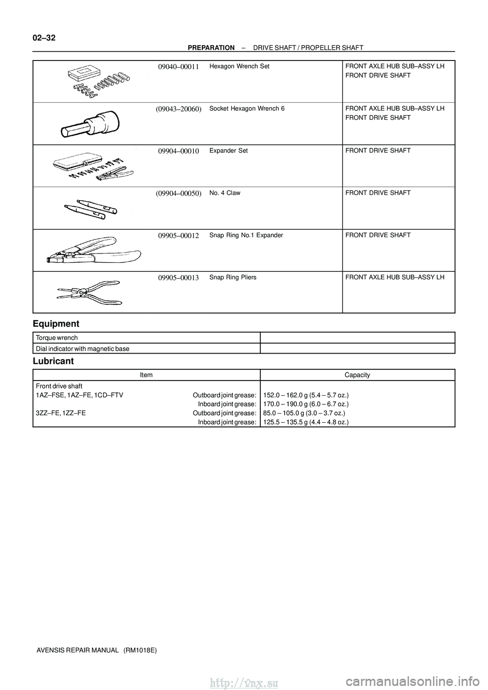
09040±00011Hexagon Wrench SetFRONT AXLE HUB SUB±ASSY LH
FRONT DRIVE SHAFT
(09043±20060)Socket Hexagon Wrench 6FRONT AXLE HUB SUB±ASSY LH
FRONT DRIVE SHAFT
09904±00010Expander SetFRONT DRIVE SHAFT
(09904±00050)No. 4 ClawFRONT DRIVE SHAFT
09905±00012Snap Ring No.1 ExpanderFRONT DRIVE SHAFT
09905±00013Snap Ring PliersFRONT AXLE HUB SUB±ASSY LH
Equipment
Torque wrench
Dial indicator with magnetic base
Lubricant
ItemCapacity
Front drive shaft
1AZ±FSE, 1AZ±FE, 1CD±FTV Outboard joint grease: Inboard joint grease:
3ZZ±FE, 1ZZ±FE Outboard joint grease: Inboard joint grease:
152.0 ± 162.0 g (5.4 ± 5.7 oz.)
170.0 ± 190.0 g (6.0 ± 6.7 oz.)
85.0 ± 105.0 g (3.0 ± 3.7 oz.)
125.5 ± 135.5 g (4.4 ± 4.8 oz.)
http://vnx.su
Page 678 of 2234
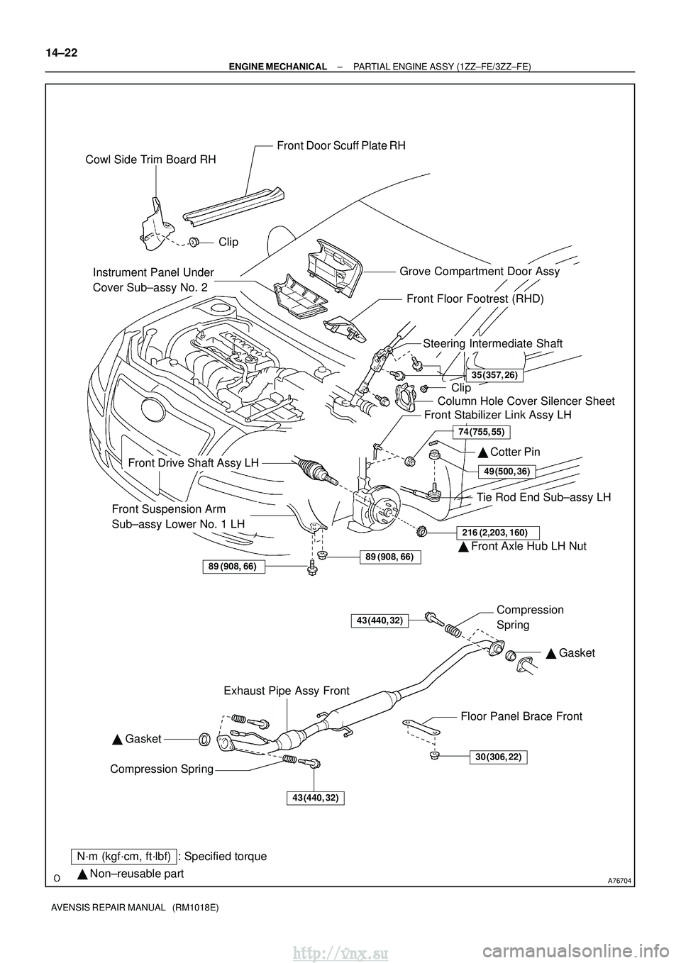
A76704
Grove Compartment Door Assy
Cowl Side Trim Board RH
Front Door Scuff Plate RH
Clip
Clip
Column Hole Cover Silencer Sheet
Steering Intermediate Shaft
� Cotter Pin
Tie Rod End Sub±assy LH
Front Suspension Arm
Sub±assy Lower No. 1 LH
Front Drive Shaft Assy LH
Front Stabilizer Link Assy LH
Exhaust Pipe Assy Front Floor Panel Brace FrontCompression
Spring
Compression Spring �
Gasket
� Gasket
89 (908, 66)
216 (2,203, 160)
49 (500, 36)
74 (755, 55)
35 (357, 26)
89 (908, 66)� Front Axle Hub LH Nut
� Non±reusable part
N´m (kgf´cm, ft´lbf) : Specified torque
43 (440, 32)
30 (306, 22)
43 (440, 32)
Front Floor Footrest (RHD)
Instrument Panel Under
Cover Sub±assy No. 2
14±22
±
ENGINE MECHANICAL PARTIAL ENGINE ASSY (1ZZ±FE/3ZZ±FE)
AVENSIS REPAIR MANUAL (RM1018E)
http://vnx.su
Page 687 of 2234
A64005
±
ENGINE MECHANICAL PARTIAL ENGINE ASSY (1ZZ±FE/3ZZ±FE)
14±31
AVENSIS REPAIR MANUAL (RM1018E)
40.REMOVE GENERATOR ASSY (See page 19±7)
41. SEPARATE COMPRESSOR AND MAGNETIC CLUTCH (W/ AIR CONDITIONING)
HINT:
�Secure the compressor and hoses off to the side instead of discharging the A/C system.
�1ZZ±FE (See page 55±74)
�3ZZ±FE (See page 55±70)
42. REMOVE COLUMN HOLE COVER SILENCER SHEET
(a) Remove the 2 clips and the column hole cover silencer sheet.
43.SEPARATE STEERING INTERMEDIATE SHAFT (See page 50±9)
44.REMOVE FRONT DOOR SCUFF PLATE RH (See page 71±11)
45.REMOVE COWL SIDE TRIM BOARD RH (See page 71±11)
46. REMOVE FRONT FLOOR FOOTREST
47. REMOVE FLOOR PANEL BRACE FRONT
(a) Remove the 2 nuts and the floor panel brace front.
48.REMOVE EXHAUST PIPE ASSY FRONT (See page 15±2)
49.REMOVE FRONT AXLE HUB LH NUT (See page 30±6)
SST 09930±00010
50. REMOVE FRONT AXLE HUB RH NUT SST 09930±00010
HINT:
Perform the same procedure as above on the opposite side.
51.SEPARATE TIE ROD END SUB±ASSY LH (See page 30±6)
SST 09628±62011
52. SEPARATE TIE ROD END SUB±ASSY RH SST 09628±62011
HINT:
Perform the same procedure as above on the opposite side.
53.SEPARATE FRONT STABILIZER LINK ASSY LH (See page 30±6)
54. SEPARATE FRONT STABILIZER LINK ASSY RH
HINT:
Perform the same procedure as above on the opposite side.
55.SEPARATE FRONT SUSPENSION ARM SUB±ASSY LOWER NO.1 LH (See page 30±6)
56. SEPARATE FRONT SUSPENSION ARM SUB±ASSY LOWER NO.1 RH
HINT:
Perform the same procedure as above on the opposite side.
57.SEPARATE FRONT AXLE ASSY LH (See page 30±6)
58. SEPARATE FRONT AXLE ASSY RH
HINT:
Perform the same procedure as above on the opposite side.
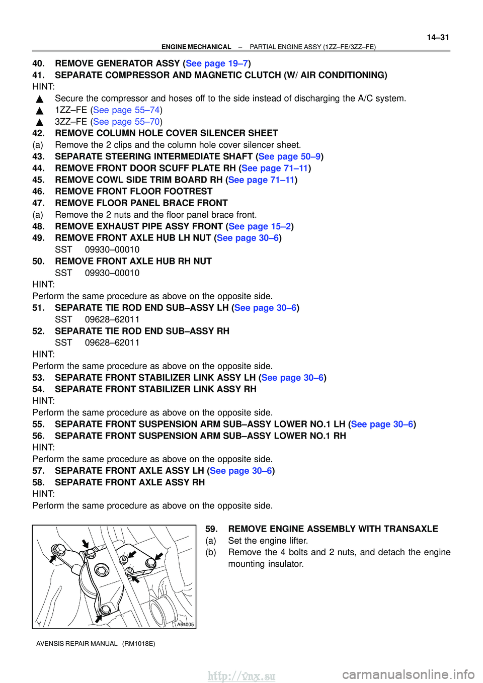
59. REMOVE ENGINE ASSEMBLY WITH TRANSAXLE
(a) Set the engine lifter.
(b) Remove the 4 bolts and 2 nuts, and detach the enginemounting insulator.
http://vnx.su
Page 1057 of 2234
C83023
C80293
30±26
±
DRIVE SHAFT / PROPELLER SHAFTFRONT AXLE HUB SUB±ASSY LH
AVENSIS REPAIR MANUAL (RM1018E)
19.INSTALL LOWER BALL JOINT ASSY FRONT LH
(a)Install the lower ball joint and torque the nut. Torque: 103 N�m (1,050 kgf�cm, 76 ft�lbf)
(b)Install a new cotter pin.
NOTICE:
If the holes for the cotter pin are not aligned, tighten the nut up to 6\
0� further.
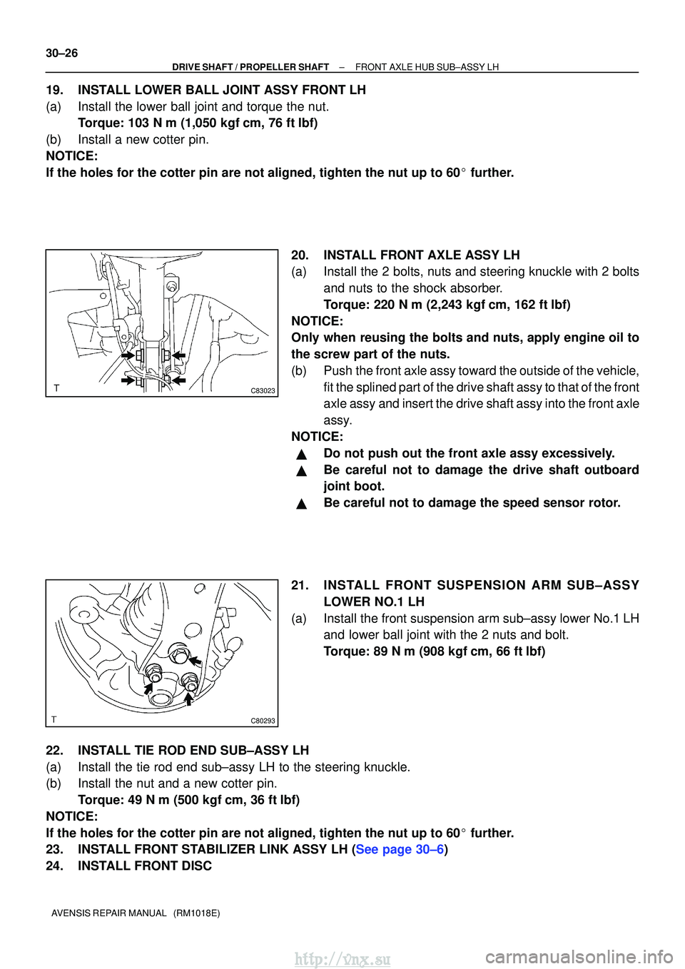
20.INSTALL FRONT AXLE ASSY LH
(a)Install the 2 bolts, nuts and steering knuckle with 2 boltsand nuts to the shock absorber.
Torque: 220 N�m (2,243 kgf�cm, 162 ft�lbf)
NOTICE:
Only when reusing the bolts and nuts, apply engine oil to
the screw part of the nuts.
(b)Push the front axle assy toward the outside of the vehicle, fit the splined part of the drive shaft assy to that of the front
axle assy and insert the drive shaft assy into the front axle
assy.
NOTICE:
�Do not push out the front axle assy excessively.
�Be careful not to damage the drive shaft outboard
joint boot.
�Be careful not to damage the speed sensor rotor.
21.INSTALL FRONT SUSPENSION ARM SUB±ASSY LOWER NO.1 LH
(a)Install the front suspension arm sub±assy lower No.1 LH and lower ball joint with the 2 nuts and bolt.
Torque: 89 N �m (908 kgf�cm, 66 ft�lbf)
22.INSTALL TIE ROD END SUB±ASSY LH
(a)Install the tie rod end sub±assy LH to the steering knuckle.
(b)Install the nut and a new cotter pin. Torque: 49 N �m (500 kgf�cm, 36 ft�lbf)
NOTICE:
If the holes for the cotter pin are not aligned, tighten the nut up to 6\
0� further.
23.INSTALL FRONT STABILIZER LINK ASSY LH (See page 30±6)
24. INSTALL FRONT DISC
http://vnx.su
Page 1062 of 2234
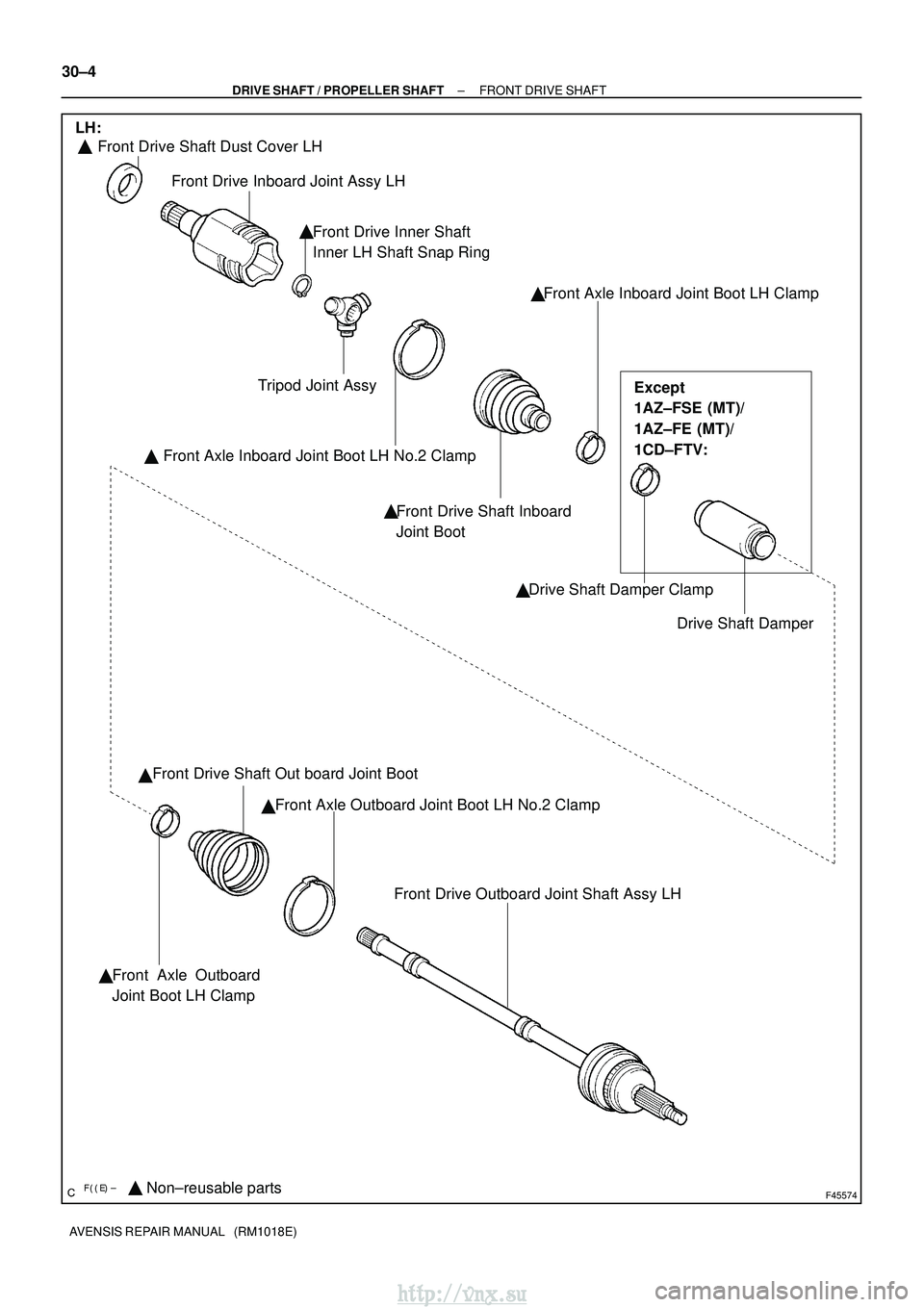
������F45574Non±reusable parts
� �
Front Drive Shaft Dust Cover LH
Front Drive Inboard Joint Assy LH
Front Drive Inner Shaft
Inner LH Shaft Snap Ring Front Axle Inboard Joint Boot LH Clamp
Drive Shaft Damper
Drive Shaft Damper Clamp
Front Drive Shaft Inboard
Joint Boot
Front Axle Inboard Joint Boot LH No.2 Clamp
Tripod Joint Assy
�
� ��
�
Front Drive Shaft Out board Joint Boot
Front Axle Outboard Joint Boot LH No.2 Clamp
�
Front Drive Outboard Joint Shaft Assy LH
Front Axle Outboard
Joint Boot LH Clamp
LH:
Except
1AZ±FSE (MT)/
1AZ±FE (MT)/
1CD±FTV:
�
�
30±4
±
DRIVE SHAFT / PROPELLER SHAFT FRONT DRIVE SHAFT
AVENSIS REPAIR MANUAL (RM1018E)
http://vnx.su
Page 1063 of 2234
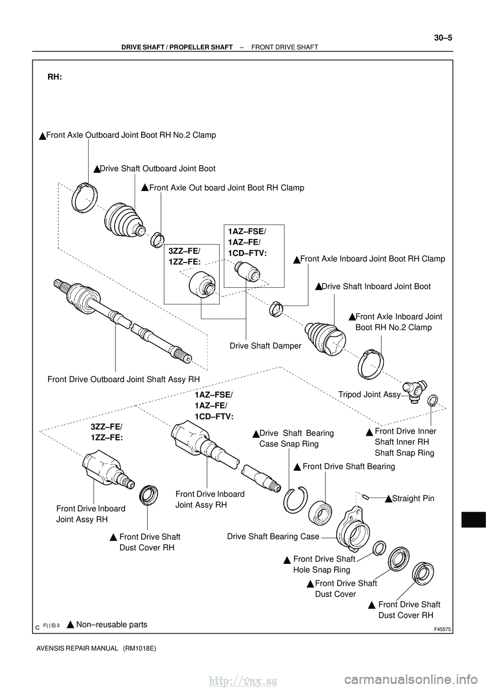
������F45575Non±reusable parts
�
Front Axle Outboard Joint Boot RH No.2 Clamp
Drive Shaft Outboard Joint BootFront Axle Out board Joint Boot RH Clamp
Drive Shaft DamperFront Axle Inboard Joint Boot RH Clamp
Drive Shaft Inboard Joint Boot
Front Axle Inboard Joint
Boot RH No.2 Clamp
�
�
Front Drive Outboard Joint Shaft Assy RH
RH:
3ZZ±FE/
1ZZ±FE: 1AZ±FSE/
1AZ±FE/
1CD±FTV:
Front Drive Inboard
Joint Assy RH
Front Drive Shaft
Dust Cover RH Tripod Joint Assy
Front Drive Inner
Shaft Inner RH
Shaft Snap Ring
Drive Shaft Bearing
Case Snap Ring
Front Drive Shaft Bearing
Straight Pin
Drive Shaft Bearing Case Front Drive Shaft
Hole Snap RingFront Drive Shaft
Dust Cover Front Drive Shaft
Dust Cover RH
�
� �
�
� �
�
�
3ZZ±FE/
1ZZ±FE:
1AZ±FSE/
1AZ±FE/
1CD±FTV:
Front Drive Inboard
Joint Assy RH �
�
��
±
DRIVE SHAFT / PROPELLER SHAFT FRONT DRIVE SHAFT
30±5
AVENSIS REPAIR MANUAL (RM1018E)
http://vnx.su
Page 1470 of 2234
610EA±01
B66569
Protrusion Part
Front
Front
Mark
Protrusion Part
61±20
±
SEAT BELT REAR SEAT BELT (LIFTBACK MODELS)
AVENSIS REPAIR MANUAL (RM1018E)
REPLACEMENT
HINT:
�The installation is in the reverse order of the removal. However, when there is a special point concern-
ing the installation, it is indicated.
�Use the same procedures on the LH side as on the RH side.
1.REMOVE REAR DOOR SCUFF PLATE RH (See page 76±45)
2. REMOVE REAR DOOR OPENING TRIM WEATHERSTRIP RH
3.REMOVE REAR SEAT ASSY (See page 72±21)
4.REMOVE PACKAGE TRAY TRIM PANEL ASSY (See page 76±45)
5. REMOVE BACK DOOR WEATHERSTRIP
6.REMOVE REAR FLOOR FINISH PLATE (See page 76±45)
7.REMOVE ROOF SIDE GARNISH INNER RH (See page 76±45)
8.REMOVE DECK TRIM SIDE PANEL ASSY RH (See page 76±45)
9. REMOVE REAR SEAT 3 POINT TYPE BELT ASSY OUTER
(a) Remove the bolt and belt on the floor anchor side.
(b) Remove the 2 bolts and belt on the retractor side.
10. REMOVE REAR SEAT BELT ASSY OUTER CENTER
(a)Remove the rear seatback board RH (See page 72±21).
(b)Remove the rear seat shoulder belt cover (See page 72±21).
(c) Remove the bolt on the retractor side and remove the belt completely.
(d) Remove the bolt and belt assy outer center on the floor anchor side.
11. REMOVE REAR SEAT 3 POINT TYPE BELT ASSY INNER
(a) Remove the bolt and belt.
12. REMOVE REAR SEAT 3 POINT TYPE BELT ASSY INNER
(a) Remove the bolt and belt.
13. REMOVE CHILD RESTRAINT SEAT ANCHOR BRACKET SUB±ASSY RH
(a) Remove the 2 bolts and anchor bracket.
14. INSTALL CHILD RESTRAINT SEAT ANCHOR BRACKET SUB±ASSY RH
(a) Install the child restraint seat anchor bracket with the 2 bolts. Torque: 31 N �m (316 kgf� cm, 23 ft�lbf)
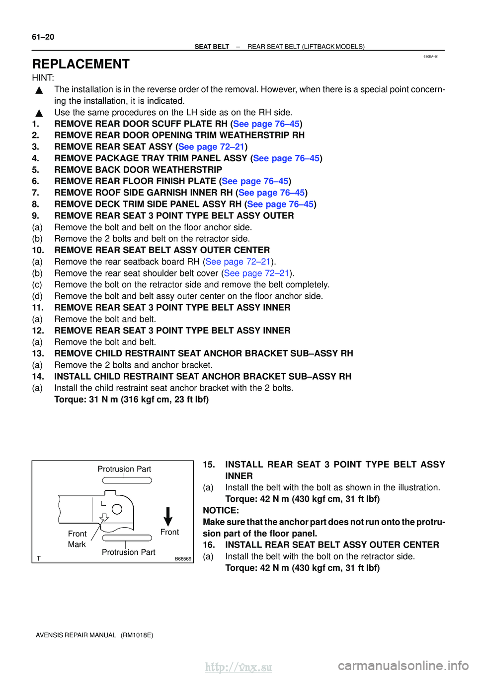
15. INSTALL REAR SEAT 3 POINT TYPE BELT ASSY INNER
(a) Install the belt with the bolt as shown in the illustration.
Torque: 42 N �m (430 kgf� cm, 31 ft�lbf)
NOTICE:
Make sure that the anchor part does not run onto the protru-
sion part of the floor panel.
16. INSTALL REAR SEAT BELT ASSY OUTER CENTER
(a) Install the belt with the bolt on the retractor side. Torque: 42 N �m (430 kgf� cm, 31 ft�lbf)
http://vnx.su