Page 186 of 2234
 Part Tightenedft�lbf
kgf�cm
N�m
Engine mounting bracket x No, 2 RH x Transverse engine
engine mounting insulatorA
B")
±
SERVICE SPECIFICATIONSENGINE MECHANICAL
03±17
AVENSIS REPAIR MANUAL (RM1018E) Part Tightenedft�lbf
kgf�cm
N�m
Engine mounting bracket x No, 2 RH x Transverse engine
engine mounting insulatorA
B
52
113530
1,15238
83
Clutch release cylinder x manual transaxleBolt A
Bolt B
Bolt C12
9.0
5.0122 92
5189
80 in.�lbf
44 in.�lbf
Vane pump assy x Timing chain cover4343931
Front suspension arm sub±assy lower No. 1 x Lower ball joint1271,29694
Front stabilizer link assy x Front suspension7475555
Floor panel brace front x Floor3030622
Engine service cover bracket RH x Body w/o Air conditioning
RHD (w/ Air conditioning) steering position type
9.0
9.092
9280 in.�lbf
80 in.�lbf
Cooler bracket x BodyLHD (w/ Air conditioning) steering position type9.09280 in.�lbf
Oil reservoir bracket No. 1 x Body8.08271 in.�lbf
Return tube sub±assy x Frame8.08271 in.�lbf
Radiator reserve tank x sub±assy x body5.05144 in.�lbf
Compressor and magnetic clutch x Cylinder blockw/ Air conditioning2525518
Radiator relay block x Frame5.05144 in.�lbf
Engine cover No. 1 x Cylinder head cover7.07162 in.�lbf
Air cleaner assy x Body5.05144 in.�lbf
Cylinder head x Cylinder block1st
2nd79
Turn 90�806
Turn 90�58
Turn 90�
Camshaft timing control valve assy x Cylinder head9.09280 in.�lbf
Camshaft timing gear assy x Camshaft5455140
Camshaft timing sprocket x Camshaft5455140
Camshaft bearing cap No. 1 x Cylinder head3030122
Camshaft bearing cap No. 2 x Cylinder head3030122
Camshaft bearing cap No. 3 x Cylinder head9.09280 in.�lbf
Chain tensioner assy No. 1 x Timing chain cover9.09280 in.�lbf
Chain tensioner plate x Stiffening crankcase assy121229
Oil pump drive sprocket x Oil pump3030122
Chain vibration damper No. 1 x Cylinder head9.09280 in.�lbf
Chain vibration damper No. 1 x Cylinder block9.09280 in.�lbf
Timing chain guide x Cylinder block9.09280 in.�lbf
Chain tensioner slipper x Cylinder block1919414
Timing chain cover (See page 14±139)Bolt A Bolt B
Bolt C Nut9.021
43
9.092
214
438 9280 in.� lbf
15
32
80 in.� lbf
Oil pan x Stiffening crankcase assy9.09280 in.�lbf
Oil pan drain plug x Oil pan2525518
Crankshaft pulley x Crankshaft1701,733125
Cylinder head cover x Cylinder head Bolt A
Bolt B
Bolt C11
14
2111 2
143
2148.0 10
15
1AZ±FSE:
Part TightenedN �mkgf �cmft �lbf
Front wheel RH1031,05076
Drain plug (M/T)4950036
Engine hanger No.1 x Cylinder head3838728
Engine hanger No.2 x Cylinder head3838728
Engine coolant temperature sensor x Cylinder head2020815
http://vnx.su
Page 447 of 2234
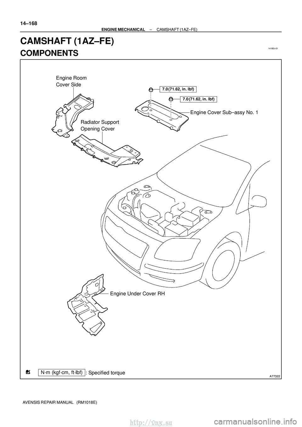
141BG±01
A77322
7.0 (71.62, in.�lbf)
7.0 (71.62, in.� lbf)
Engine Room
Cover Side
Radiator Support
Opening Cover Engine Cover Sub±assy No. 1
Engine Under Cover RH
N´m (kgf´cm, ft´lbf) : Specified torque
14±168
±
ENGINE MECHANICAL CAMSHAFT (1AZ±FE)
AVENSIS REPAIR MANUAL (RM1018E)
CAMSHAFT (1AZ±FE)
COMPONENTS
http://vnx.su
Page 448 of 2234
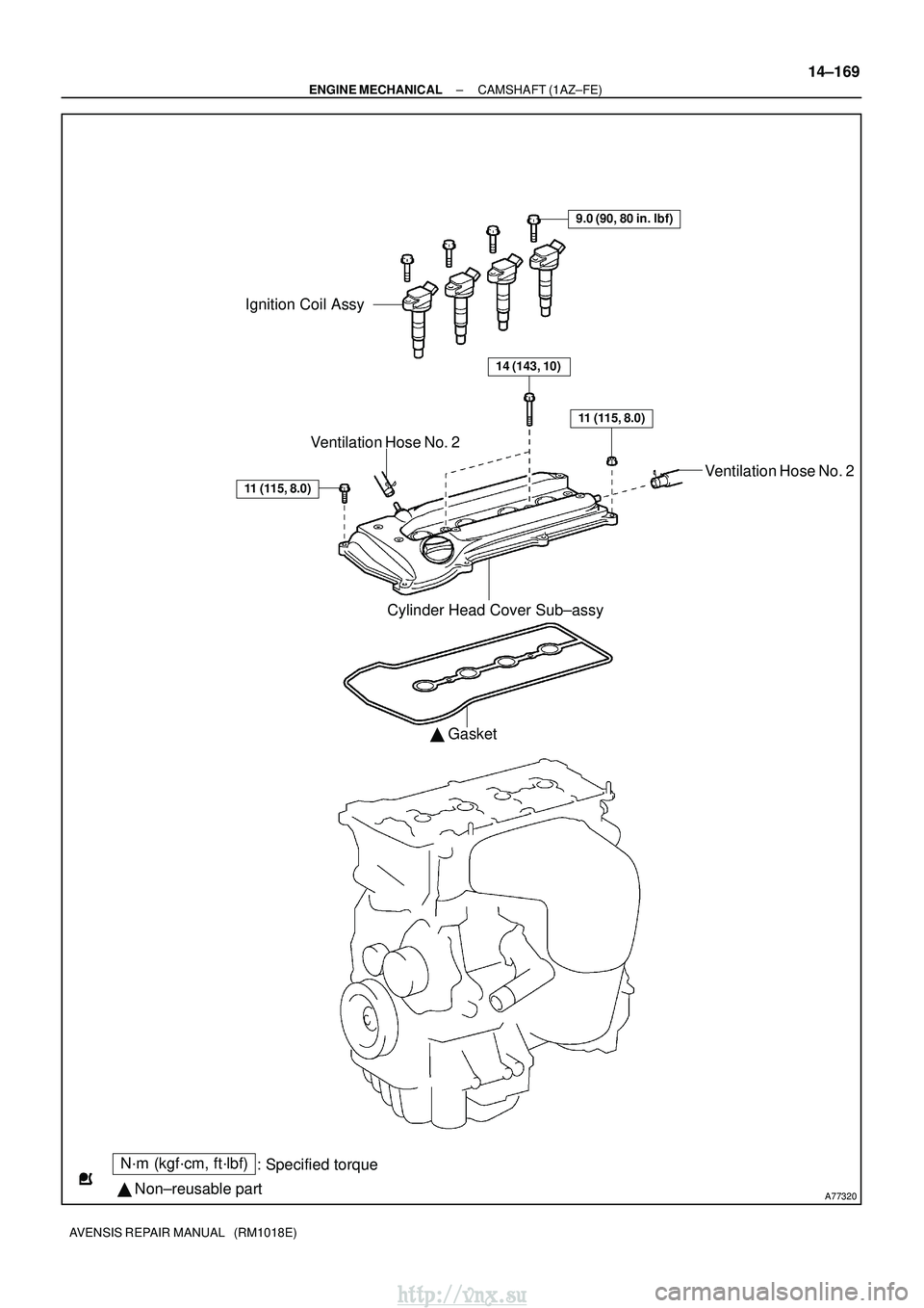
A77320
N´m (kgf´cm, ft´lbf): Specified torque
� Non±reusable part
Ignition Coil Assy
9.0 (90, 80 in. �lbf)
14 (143, 10)
11 (115, 8.0)
Cylinder Head Cover Sub±assy
� Gasket
11 (115, 8.0)
Ventilation Hose No. 2
Ventilation Hose No. 2
±
ENGINE MECHANICAL CAMSHAFT (1AZ±FE)
14±169
AVENSIS REPAIR MANUAL (RM1018E)
http://vnx.su
Page 449 of 2234
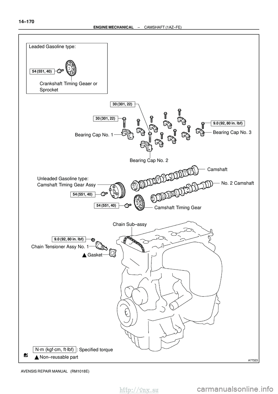
A77323
Leaded Gasoline type:
N´m (kgf´cm, ft´lbf): Specified torque
� Non±reusable part
54 (551, 40)
� Gasket
Crankshaft Timing Geaer or
Sprocket
Bearing Cap No. 3
Bearing Cap No. 2
Camshaft
No. 2 Camshaft
Camshaft Timing Gear
Unleaded Gasoline type:
Camshaft Timing Gear Assy
54 (551, 40)
Chain Tensioner Assy No. 1
30 (301, 22)
Bearing Cap No. 1
30 (301, 22)
9.0 (92, 80 in. �lbf)
54 (551, 40)
9.0 (92, 80 in. �lbf)
Chain Sub±assy
14±170
±
ENGINE MECHANICAL CAMSHAFT (1AZ±FE)
AVENSIS REPAIR MANUAL (RM1018E)
http://vnx.su
Page 450 of 2234
141BK±01
A77281
A77283
A77284
±
ENGINE MECHANICAL CAMSHAFT (1AZ±FE)
14±171
AVENSIS REPAIR MANUAL (RM1018E)
REPLACEMENT
1. REMOVE RADIATOR SUPPORT OPENING COVER
2. REMOVE ENGINE ROOM COVER SIDE
3. REMOVE ENGINE UNDER COVER RH
4. REMOVE ENGINE COVER SUB±ASSY NO.1
(a) Remove the 2 nuts and the engine cover No. 1.
5. REMOVE IGNITION COIL ASSY
(a) Remove 4 bolts and the ignition coils. 6. REMOVE CYLINDER HEAD COVER SUB±ASSY
(a) Disconnect the 2 PCV hoses from the cylinder head cov-er.
(b) Remove the 8 bolts and 2 nuts, and then remove the cylin- der head cover and gasket.
7. SET NO. 1 CYLINDER TO TDC/COMPRESSION
(a) Turn the crankshaft pulley, and align its timing notch with timing mark 0 of the timing chain cover.
http://vnx.su
Page 451 of 2234

AVENSI")
A77285
Unleaded Gasoline
Leaded GasolineTiming
Marks
Timing
Marks
Timing
Marks
Timing
Marks
A77286
Push
A77412
HoldLoosen
A77294
15973
481062
14±172
±
ENGINE MECHANICAL CAMSHAFT (1AZ±FE)
AVENSIS REPAIR MANUAL (RM1018E)
(b) Check that each timing mark of the camshaft timing gears is aligned with each timing mark located on the No. 1 and
No. 2 bearing caps as shown in the illustration.
If not, turn the crankshaft 1 revolution (360 �) and align the
marks as above.
8. REMOVE CHAIN TENSIONER ASSY NO.1
(a) Remove the 2 nuts, then remove the chain tensioner and a gasket.
NOTICE:
Do not turn the crankshaft.
9. REMOVE NO.2 CAMSHAFT
(a) Hold the No. 2 camshaft with a wrench on the hexagonal lobe, and loosen the camshaft timing gear set bolt.
NOTICE:
Be careful not to damage the cylinder head and valve lifter
with the wrench.
(b) Using several steps, loosen and remove the 10 camshaft
bearing cap bolts uniformly in the sequence shown in the
illustration.
(c) Remove the 5 camshaft bearing caps.
http://vnx.su
Page 452 of 2234

14±173
AVENSIS REPAIR MANUAL (RM1018E)
(d) Raising the No. 2 camshaft, remove the set bolt.
(e) Re")
A52473
A77309
15973
481062
A56228
A77413
Advance
Side Port
±
ENGINE MECHANICAL CAMSHAFT (1AZ±FE)
14±173
AVENSIS REPAIR MANUAL (RM1018E)
(d) Raising the No. 2 camshaft, remove the set bolt.
(e) Remove the camshaft timing gear from the No. 2 cam-
shaft with the timing chain wrapped.
(f) Remove the camshaft timing gear from the timing chain.
10. REMOVE CAMSHAFT
(a) Using several steps, loosen and remove the 10 camshaft bearing cap bolts uniformly in the sequence shown in the
illustration.
(b) Remove the 5 camshaft bearings.
(c) Remove the camshaft.
(d) Tie the timing chain as shown in the illustration.
NOTICE:
�Be careful not to drop anything inside the timing
chain cover.
�Do not expose the chain to water, and prevents dust.
11. REMOVE CAMSHAFT TIMING GEAR OR SPROCKET (LEADED GASOLINE)
(a) Clamp the camshaft in a vise and remove the bolt and the camshaft timing\
gear. 12. REMOVE CAMSHAFT TIMING GEAR ASSY(UNLEADED GASOLINE)
(a) Fix the camshaft with a vise, and make sure the camshaft
timing gear does not rotate.
(b) Cover all the oil ports with vinyl tape except an advance side port shown in the illustration.
http://vnx.su
Page 453 of 2234

AVENSIS REPAIR MANUAL (RM1018E)
(c) Put air pressure into the oil port with 150 kpa (1.5 kgf/cm2
21 psi),")
A31032
A32639
A77414
Straight
Pin
Key
Groove
14±174
±
ENGINE MECHANICAL CAMSHAFT (1AZ±FE)
AVENSIS REPAIR MANUAL (RM1018E)
(c) Put air pressure into the oil port with 150 kpa (1.5 kgf/cm2
21 psi), and turn the camshaft timing gear to the advance
direction (counterclockwise) by hand.
CAUTION:
Cover the paths with shop rag to avoid oil splashing.
HINT:
Depending on the air pressure, the camshaft timing gear will
turn to the advance angle side without applying force by hand.
Also, under the condition that the pressure can be hardly ap-
plied because of the air leakage from the port, there may be the
case that the lock pin could be hardly released.
(d) Remove the fringe bolt of camshaft timing gear.
NOTICE:
�Be sure not to remove the other 4 bolts.
�If reusing the camshaft timing gear, release the
straight pin lock first, and then install the gear.
13. INSTALL CAMSHAFT TIMING GEAR OR SPROCKET (LEADED GASOLINE) Torque: 54 N �m (551 kgf� cm, 40 ft�lbf)
14. INSTALL CAMSHAFT TIMING GEAR ASSY (UNLEADED GASOLINE)
(a) Put the camshaft timing gear and the camshaft together with the straight pin off the key groove.
(b) Turn the camshaft timing gear assembly to the left direc- tion (as shown in the illustration) while lightly pushing it to-
ward the camshaft. Push further at the position where the
pin gets into the groove.
NOTICE:
Be sure not to turn the camshaft timing gear to the retard
angle side (to the right direction).
(c) Check that there is no clearance between the gear's fringe and the camshaft.
(d) Tighten the fringe bolt with the camshaft timing gear fixed. Torque: 54 N� m (551 kgf�cm, 40 ft�lbf)
(e) Check that the camshaft timing gear can move to the re- tard angle side (to the right direction), and is locked at the
most retarded position.
http://vnx.su

14±171
AVENSIS REPAIR MANUAL (RM1018E)
REPLACEMENT
1. REMOVE RADIATOR SUPPORT OPENING COVER
2. REMOVE ENGINE ROOM COVER SIDE
3")