Page 375 of 2234

11±107
AVENSIS REPAIR MANUAL (RM1018E)
16. DISCONNECT FUEL TANK MAIN TUBE SUB±ASS")
A81588
31
22
A63387
Retainer
Fuel Tube Connector
O±ring
Pipe
A77890
A77894
A78270
±
FUEL FUEL TANK ASSY (DIESEL)
11±107
AVENSIS REPAIR MANUAL (RM1018E)
16. DISCONNECT FUEL TANK MAIN TUBE SUB±ASSY
(a) Pinch the tab of the retainer to remove the lock claws and
pull down it as shown in the illustration.
(b) Pull out the fuel tank main tube.
NOTICE:
�Check if there is any dirt or mud around the connector
before this operation and remove the dirt as neces-
sary.
�Be careful of mud because the quick connector has
an O±ring which seals the pipe and the connector that
can be contaminated.
�Do not use any tool in this operation.
�Do not bend or twist the nylon tube. Protect the con-
nector by covering it with a vinyl or a plastic bag.
�When the pipe and connector are stuck, push and pull
the connector to release. Pull out the connector from
the pipe carefully.
17. REMOVE FUEL TANK ASSY
(a) Set up a transmission jack under the fuel tank.
(b) Remove the 4 bolts and 2 fuel tank bands, and then re- move the fuel tank.
18. REMOVE FUEL TANK MAIN TUBE SUB±ASSY
(a) Unfasten the 5 claws, and remove the fuel tank return tube from the fuel tank.
19. REMOVE FUEL EVAPORATION TUBE SUB±ASSY NO.2
(a) Unfasten the claw, and remove the fuel evaporation tube
from the fuel tank.
http://vnx.su
Page 387 of 2234

A77888
1
2
3
Retainer
Pinch
Pinch
2
A63387
RetainerPipe
O±ring
Fuel Tube Connector
A77889
2
Pinch1
Pinch1
A60576
Nylon Tube
Pipe
O±ring Fuel Tube
Connector Clip
Fuel Tube
Connector
A77890
±
FUEL FUEL TANK ASSY (GASOLINE)
11±97
AVENSIS REPAIR MANUAL (RM1018E)
19. DISCONNECT FUEL TANK MAIN TUBE SUB±ASSY
(a) Pinch the tab of the retainer to remove the lock claws and
pull down it as shown in the illustration.
(b) Pull out the fuel tank main tube.
NOTICE:
�Check if there is any dirt or mud around the connector
before this operation and remove the dirt as neces-
sary.
�Be careful of mud because the quick connector has
an O±ring which seals the pipe and the connector that
can be contaminated.
�Do not use any tool in this operation.
�Do not bend or twist the nylon tube. Protect the con-
nector by covering it with a vinyl or plastic bag.
�When the pipe and connector are stuck, push and pull
the connector to release. Pull out the connector from
the pipe.
20. DISCONNECT FUEL EVAPORATION TUBE SUB±ASSY NO.2
(a) Pinch the fuel tube connector clip and pull out the fuel evaporation tube.
NOTICE:
�Check if there is any dirt or mud around the connector
before this operation and remove the dirt as neces-
sary.
�Be careful of mud because the quick connector has
an O±ring which seals the pipe and the connector that
can be contaminated.
�Do not use any tool in this operation.
�Do not bend or twist the nylon tube. Protect the con-
nector by covering it with a vinyl or plastic bag.
�When the pipe and connector are stuck, push and pull
the connector to release. Pull out the connector from
the pipe.
21. REMOVE FUEL TANK ASSY
(a) Set a transmission jack to the fuel tank.
(b) Remove the 4 bolts and the 2 fuel tank bands, and then remove the fuel tank.
http://vnx.su
Page 429 of 2234
1302G±03
A77131
Vacuum Gage
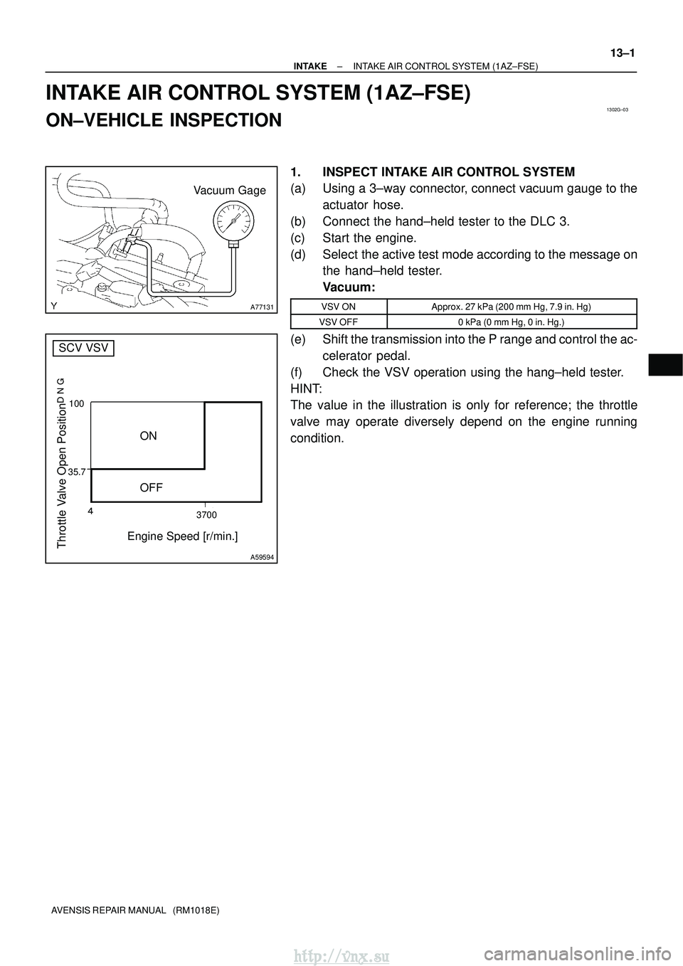
35.7� 3700
100
Throttle Valve Open Position
���
Engine Speed [r/min.]
ON
OFF
A59594
SCV VSV
±
INTAKE INTAKE AIR CONTROL SYSTEM (1AZ±FSE)
13±1
AVENSIS REPAIR MANUAL (RM1018E)
INTAKE AIR CONTROL SYSTEM (1AZ±FSE)
ON±VEHICLE INSPECTION
1. INSPECT INTAKE AIR CONTROL SYSTEM
(a) Using a 3±way connector, connect vacuum gauge to the
actuator hose.
(b) Connect the hand±held tester to the DLC 3.
(c) Start the engine.
(d) Select the active test mode according to the message on the hand±held tester.
Vacuum:
VSV ONApprox. 27 kPa (200 mm Hg, 7.9 in. Hg)
VSV OFF0 kPa (0 mm Hg, 0 in. Hg.)
(e) Shift the transmission into the P range and control the ac-
celerator pedal.
(f) Check the VSV operation using the hang±held tester.
HINT:
The value in the illustration is only for reference; the throttle
valve may operate diversely depend on the engine running
condition.
http://vnx.su
Page 598 of 2234

14±101
AVENSIS REPAIR MANUAL (RM1018E)
ENGINE(1AZ±FE)
INSPECTION
1.INSPECT COOLANT (See page 16±13)
2.INSPECT ENGINE OIL (See page")
140D1±02
CG
TCA51075
A52004
±
ENGINE MECHANICALENGINE(1AZ±FE)
14±101
AVENSIS REPAIR MANUAL (RM1018E)
ENGINE(1AZ±FE)
INSPECTION
1.INSPECT COOLANT (See page 16±13)
2.INSPECT ENGINE OIL (See page 17±6)
3. INSPECT BATTERY
Standard specific gravity: 1.25 to 1.29 at 20� C (68�F)
4. INSPECT AIR CLEANER FILTER ELEMENT SUB±ASSY
5.INSPECT SPARK PLUG (See page 18±9)
6. INSPECT V±RIBBED BELT
7. INSPECT IGNITION TIMING
(a) Warm up engine.
(b) When using hand±held tester:(1) Connect the hand±held tester to the DLC3.
(2) Enter DATA LIST MODE on the hand±held tester.
Ignition timing: 8 to 12 � BTDC
HINT:
Please refer to the hand±held tester operator's manual if you
need help to select DATA LIST.
(c) When not using hand±held tester:
(1) Using SST, connect terminals 13 (TC) and 4 (CG)of DLC3.
SST 09843±18040
NOTICE:
�Make sure of the terminal numbers before connecting
them. Connection with a wrong terminal can damage
the engine.
�Turn OFF all electrical systems before connecting the
terminals.
�Operate the inspection after the cooling fan motor is
turned OFF.
(2) Remove the cylinder head cover No.2.
(3) Pull out the wire harness as shown in the illustration.
Connect the clip of the timing light to the engine.
NOTICE:
�Use a timing light which detects the first signal.
�After checking, be sure to wrap the wire harness with
tape.
(4) Inspect ignition timing at idle.
Ignition timing: 8 to 12 � BTDC
NOTICE:
When checking the ignition timing, shift the transmission
to the neutral position.
HINT:
Run the engine at 1,000 to 1,300 rpm for 5 seconds, check that
the engine rpm returns to the idle speed.
http://vnx.su
Page 602 of 2234

14±181
AVENSIS REPAIR MANUAL (RM1018E)
ENGINE(1AZ±FSE)
INSPECTION
1.INSPECT COOLANT (See page 16±25)
2.INSPECT ENGINE OIL(See pag")
141CP±01
CG
TCA51075
A79034
±
ENGINE MECHANICALENGINE(1AZ±FSE)
14±181
AVENSIS REPAIR MANUAL (RM1018E)
ENGINE(1AZ±FSE)
INSPECTION
1.INSPECT COOLANT (See page 16±25)
2.INSPECT ENGINE OIL(See page 17±13)
3.INSPECT BATTERY
Standard specific gravity: 1.25 to 1.29 at 20�C (68�F)
4.INSPECT AIR CLEANER FILTER ELEMENT SUB±ASSY
5.INSPECT SPARK PLUG (See page 18±14)
6.INSPECT V±RIBBED BELT
7.INSPECT IGNITION TIMING
(a)Warm up engine.
(b)When using hand±held tester:(1)Connect the hand±held tester to the DLC3.
(2)Enter DATA LIST MODE on the hand±held tester.
Ignition timing: 8 to 12� BTDC
HINT:
Please refer to the hand±held tester operator's manual if you
need help to select DATA LIST.
(c) When not using hand±held tester:
(1) Using SST, connect terminals 13 (TC) and 4 (CG)of DLC3.
SST 09843±18040, 09843±18020
NOTICE:
�Make sure of the terminal numbers before connecting
them. Connection with a wrong terminal can damage
the engine.
�Turn OFF all electrical systems before connecting the
terminals.
�Operate the inspection after the cooling fan motor is
turned OFF
(2) Remove the cylinder head cover No.2.
(3) Pull out the wire harness as shown in the illustration.
Connect the clip of the timing light to the engine.
NOTICE:
�Use a timing light which detects the first signal.
�After checking, be sure to wrap the wire harness with
tape.
(4) Inspect ignition timing at idle.
Ignition timing: 8 to 12 � BTDC
NOTICE:
When checking the ignition timing, shift the transmission
to the neutral position.
HINT:
Run the engine at 1,000 to 1,300 rpm for 5 seconds, check that
the engine rpm returns to the idle speed. (5) Disconnect terminals 13 (TC) and 4 (CG) of DLC3.
http://vnx.su
Page 610 of 2234

AVENSIS REPAIR MANUAL (RM1018E)
(5) Inspect ignition timing at idle.
Ignition timing: 8 to 12 �BTDC
NOTICE:
When checking the i")
TA C
A52006
A01037
14±2
±
ENGINE MECHANICAL ENGINE (1ZZ±FE/3ZZ±FE)
AVENSIS REPAIR MANUAL (RM1018E)
(5) Inspect ignition timing at idle.
Ignition timing: 8 to 12 �BTDC
NOTICE:
When checking the ignition timing, shift the transmission
to the neutral position.
HINT:
Run the engine at 1,000 to 1,300 rpm for 5 seconds, check that
the engine rpm returns to the idle speed.
(6) Disconnect the terminal 13 (TC) and 4 (CG) of theDLC3.
(7) Inspect ignition timing at idle.
Ignition timing:
10 to 18 �BTDC (1ZZ±FE)
3.5 to 11.5 �BTDC (3ZZ±FE)
(8) Confirm that ignition timing to go advanced angle side when the engine rpm is increased.
(9) Remove the timing light.
(10) Install the cylinder head cover with the 2 nuts and 2 clips.
Torque: 7.0 N �m (71 kgf �cm, 62 in. �lbf)
8. INSPECT ENGINE IDLE SPEED
(a) Warm up engine.
(b) When using hand±held tester: (1) Connect the hand±held tester to the DLC3.
HINT:
Please refer to the hand±held tester operator's manual if you
need help to select DATA LIST.
(c) When not using hand±held tester:
(1) Using SST, connect the tachometer test prove toterminal 9 (TAC) of DLC3.
SST 09843±18040
(d) Check the idle speed. Idle speed: 600 to 700 rpm
NOTICE:
�Check the idle speed with the cooling fan OFF.
�Switch off all accessories and air conditioning before
connecting the test prove to the terminal.
9. INSPECT COMPRESSION
(a) Warm up and stop the engine.
(b) Remove the ignition coil.
(c) Remove the spark plugs.
(d) Inspect cylinder compression pressure. SST 09992±00500
(1) Insert a compression gauge into the spark plughole.
(2) Fully open the throttle.
http://vnx.su
Page 627 of 2234
A77314
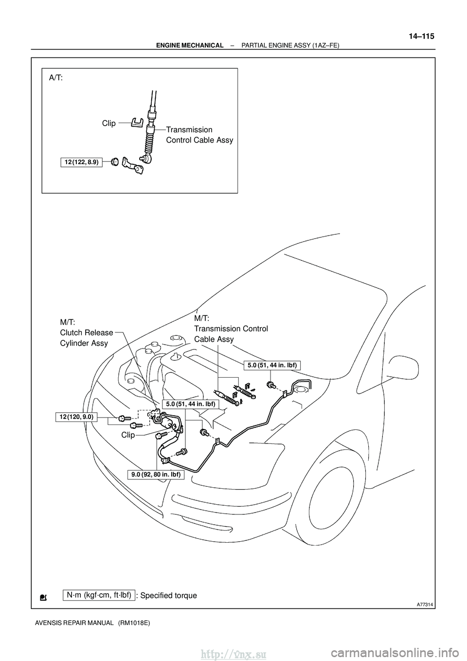
A/T:Clip Transmission
Control Cable Assy
N´m (kgf´cm, ft´lbf) : Specified torque
M/T:
Transmission Control
Cable Assy
5.0 (51, 44 in.�lbf)
12 (120, 9.0)
M/T:
Clutch Release
Cylinder Assy
12 (122, 8.9)
Clip
5.0 (51, 44 in. �lbf)
9.0 (92, 80 in. �lbf)
±
ENGINE MECHANICAL PARTIAL ENGINE ASSY (1AZ±FE)
14±115
AVENSIS REPAIR MANUAL (RM1018E)
http://vnx.su
Page 636 of 2234

AVENSIS REPAIR MANUAL (RM1018E)
40.REMOVE FRONT AXLE HUB RH NUT SST09330±00030
H")
A77298
LHD Steering Position typeRHD Steering Position type
14±124
±
ENGINE MECHANICALPARTIAL ENGINE ASSY(1AZ±FE)
AVENSIS REPAIR MANUAL (RM1018E)
40.REMOVE FRONT AXLE HUB RH NUT SST09330±00030
HINT:
Perform the same procedure as above on the opposite side.
41.SEPARATE TIE ROD END SUB±ASSY LH (See page 51±36)
42.SEPARATE TIE ROD END SUB±ASSY RH
HINT:
Perform the same procedure as above on the opposite side.
43.SEPARATE FRONT STABILIZER LINK ASSY LH (See page 26±26)
44.SEPARATE FRONT STABILIZER LINK ASSY RH
HINT:
Perform the same procedure as above on the opposite side.
45.SEPARATE FRONT SUSPENSION ARM SUB±ASSY LOWER NO.1 LH (M/T TRANSAXLE)
(See page 26±21)
46.SEPARATE FRONT SUSPENSION ARM SUB±ASSY LOWER NO.1 LH (A/T TRANSAXLE) (See page 26±16)
47.SEPARATE FRONT SUSPENSION ARM SUB±ASSY LOWER NO.1 RH (M/T TRANSAXLE)
HINT:
Perform the same procedure as above on the opposite side.
48.SEPARATE FRONT SUSPENSION ARM SUB±ASSY LOWER NO.1 RH (A/T TRANSAXLE)
HINT:
Perform the same procedure as above on the opposite side.
49.SEPARATE FRONT AXLE ASSY LH (See page 30±6)
50.SEPARATE FRONT AXLE ASSY RH (See page 30±6)
HINT:
Perform the same procedure as above on the opposite side. 51.SEPARATE CLUTCH RELEASE CYLINDER ASSY (M/TTRANSAXLE)
(a)Remove 7 bolts as shown in the illustration.
52.SEPARATE TRANSMISSION CONTROL CABLE ASSY (M/T TRANSAXLE) (See page 41±24)
53.SEPARATE TRANSMISSION CONTROL CABLE ASSY (A/T TRANSAXLE) (See page 40±25)
54. SEPARATE ACCELERATOR CONTROL CABLE ASSY
http://vnx.su