Page 668 of 2234

A79149
Fulcrum
Length
30 cm
SST
A81587
14±298
±
ENGINE MECHANICAL PARTIAL ENGINE ASSY (1CD±FTV)
AVENSIS REPAIR MANUAL (RM1018E)
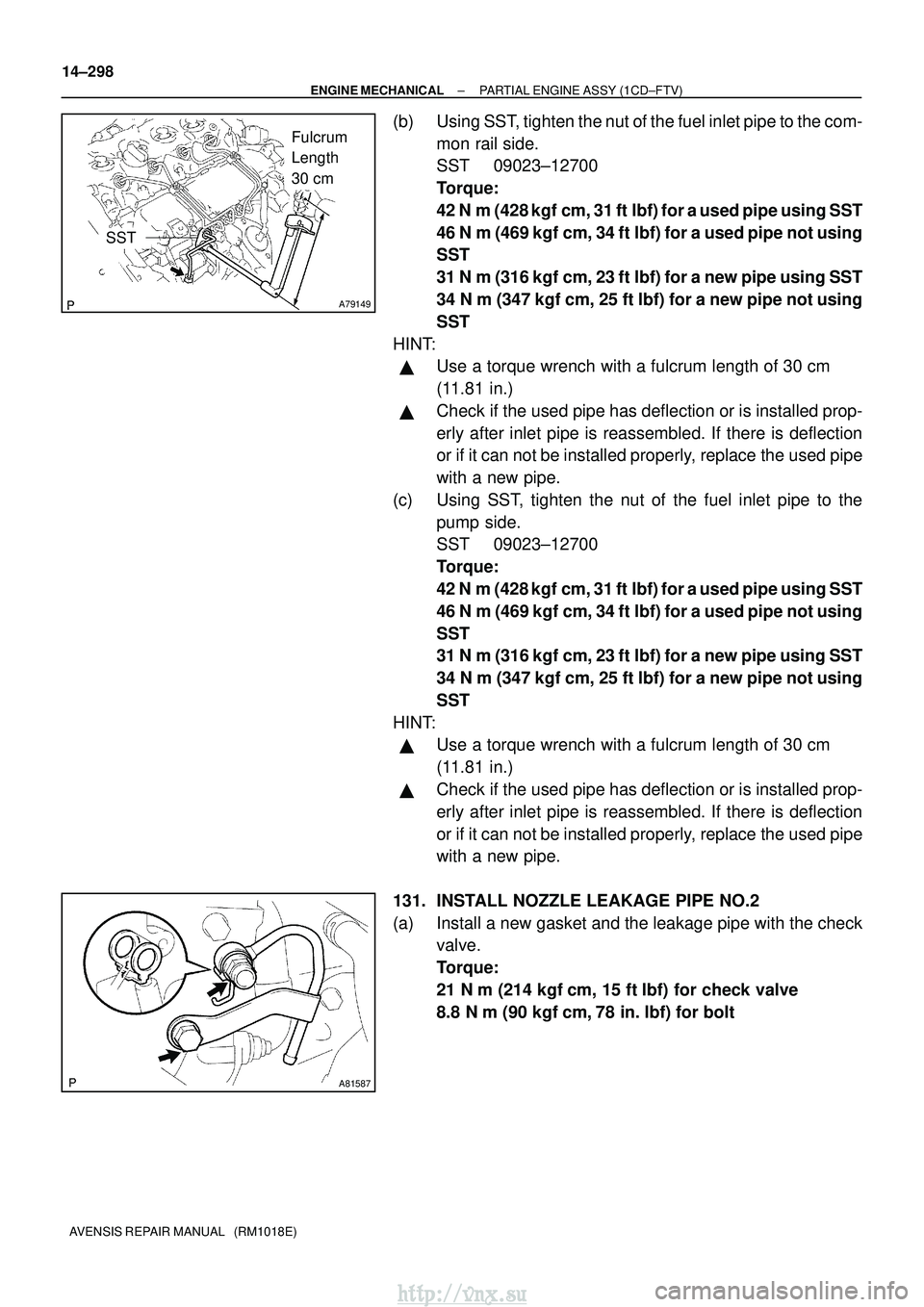
(b) Using SST, tighten the nut of the fuel inlet pipe to the com- mon rail side.
SST 09023±12700
Torque:
42 N�m (428 kgf� cm, 31 ft�lbf) for a used pipe using SST
46 N� m (469 kgf� cm, 34 ft�lbf) for a used pipe not using
SST
31 N �m (316 kgf� cm, 23 ft�lbf) for a new pipe using SST
34 N� m (347 kgf �cm, 25 ft �lbf) for a new pipe not using
SST
HINT:
�Use a torque wrench with a fulcrum length of 30 cm
(11.81 in.)
�Check if the used pipe has deflection or is installed prop-
erly after inlet pipe is reassembled. If there is deflection
or if it can not be installed properly, replace the used pipe
with a new pipe.
(c) Using SST, tighten the nut of the fuel inlet pipe to the pump side.
SST 09023±12700
Torque:
42 N�m (428 kgf� cm, 31 ft�lbf) for a used pipe using SST
46 N� m (469 kgf� cm, 34 ft�lbf) for a used pipe not using
SST
31 N �m (316 kgf� cm, 23 ft�lbf) for a new pipe using SST
34 N� m (347 kgf �cm, 25 ft �lbf) for a new pipe not using
SST
HINT:
�Use a torque wrench with a fulcrum length of 30 cm
(11.81 in.)
�Check if the used pipe has deflection or is installed prop-
erly after inlet pipe is reassembled. If there is deflection
or if it can not be installed properly, replace the used pipe
with a new pipe.
131. INSTALL NOZZLE LEAKAGE PIPE NO.2
(a) Install a new gasket and the leakage pipe with the check valve.
Torque:
21 N�m (214 kgf� cm, 15 ft�lbf) for check valve
8.8 N� m (90 kgf �cm, 78 in. �lbf) for bolt
http://vnx.su
Page 736 of 2234
A77857
A78440
New Gasket
15±8
±
EXHAUSTEXHAUST PIPE ASSY(1AZ±FE/1AZ±FSE)
AVENSIS REPAIR MANUAL (RM1018E)
5.INSTALL EXHAUST PIPE ASSY FRONT
(a)Compression spring inspection (1)Using vernier calipers, measure the free length of
the compression spring.
Minimum length: 41.5 mm (1.634 in.)
If the free length is less than minimum, replace the compression
spring.
(b)Install a new gasket to the exhaust manifold as shown in the illustration.
(c)Install the exhaust pipe front with the 2 compression springs and 2 bolts.
Torque: 43 N �m (440 kgf�cm, 32 ft�lbf)
6.INSTALL EXHAUST PIPE ASSY CENTER
(a)Install a new gasket and the exhaust pipe center to the 2 exhaust pipe s\
upports.
(b)Tighten the 2 bolts. Torque: 43 N �m (440 kgf�cm, 32 ft�lbf)
7.INSTALL EXHAUST PIPE ASSY TAIL (See page 15±2)
8. CHECK FOR EXHAUST GAS LEAKS
9.INSTALL FLOOR PANEL BRACE FRONT (See page 15±2)
http://vnx.su
Page 739 of 2234

A78272
(a)(b)
(b)
(a)
A77857
A76194
Wooden
Block
Gasket
±
EXHAUST EXHAUST PIPE ASSY (1CD±FTV)
15±11
AVENSIS REPAIR MANUAL (RM1018E)
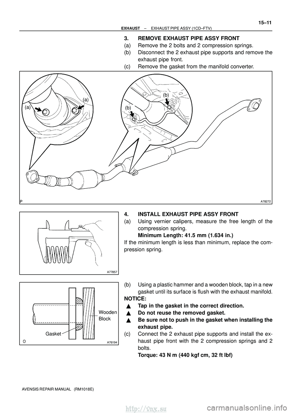
3. REMOVE EXHAUST PIPE ASSY FRONT
(a) Remove the 2 bolts and 2 compression springs.
(b) Disconnect the 2 exhaust pipe supports and remove the
exhaust pipe front.
(c) Remove the gasket from the manifold converter.
4. INSTALL EXHAUST PIPE ASSY FRONT
(a) Using vernier calipers, measure the free length of the compression spring.
Minimum Length: 41.5 mm (1.634 in.)
If the minimum length is less than minimum, replace the com-
pression spring.
(b) Using a plastic hammer and a wooden block, tap in a new gasket until its surface is flush with the exhaust manifold.
NOTICE:
�Tap in the gasket in the correct direction.
�Do not reuse the removed gasket.
�Be sure not to push in the gasket when installing the
exhaust pipe.
(c) Connect the 2 exhaust pipe supports and install the ex-
haust pipe front with the 2 compression springs and 2
bolts.
Torque: 43 N� m (440 kgf�cm, 32 ft�lbf)
http://vnx.su
Page 740 of 2234
A77857
A78440
New Gasket
15±12
±
EXHAUST EXHAUST PIPE ASSY (1CD±FTV)
AVENSIS REPAIR MANUAL (RM1018E)
5. INSTALL EXHAUST PIPE ASSY TAIL
(a) Using vernier calipers, measure the free length of the compression spring.
Minimum Length: 38.5 mm (1.515 in.)
If the minimum length is less than minimum, replace the com-
pression spring.
(b) Install a new gasket to the pipe front converter as shown in the illustration.
(c) Connect the 3 exhaust pipe supports and install the ex- haust pipe tail with the 2 compression springs and 2 bolts.
Torque: 43 N� m (440 kgf�cm, 32 ft�lbf)
6. CHECK FOR EXHAUST GAS LEAKS
7. INSTALL FLOOR PANEL BRACE FRONT Torque: 30 N �m (302 kgf� cm, 22 ft�lbf)
http://vnx.su
Page 744 of 2234
A78492
(a)(a)
(b)
(b)
A77857
A78440
New Gasket
15±4
±
EXHAUST EXHAUST PIPE ASSY (1ZZ±FE/3ZZ±FE)
AVENSIS REPAIR MANUAL (RM1018E)
6. REMOVE EXHAUST PIPE ASSY FRONT
(a) Remove the 2 bolts and 2 compression springs.
(b) Remove the exhaust pipe front from the 2 exhaust pipe supports.
(c) Remove the gasket from the exhaust manifold.
7. INSTALL EXHAUST PIPE ASSY FRONT
(a) Compression spring inspection (1) Using vernier calipers, measure the free length ofthe compression spring.
Minimum length: 41.5 mm (1.634 in.)
If the free length is less than minimum, replace the compression
spring.
(b) Install a new gasket to the exhaust manifold as shown in the illustration.
(c) Install the exhaust pipe front to the 2 exhaust pipe sup-
ports.
(d) Tighten the 2 compression springs and 2 bolts. Torque: 43 N �m (440 kgf� cm, 32 ft�lbf)
http://vnx.su
Page 745 of 2234
A77857
A78440
New Gasket
±
EXHAUST EXHAUST PIPE ASSY (1ZZ±FE/3ZZ±FE)
15±5
AVENSIS REPAIR MANUAL (RM1018E)
8. INSTALL EXHAUST PIPE ASSY TAIL
(a) Compression spring inspection
(1) Using vernier calipers, measure the free length of
the compression spring.
Minimum length: 38.5 mm (1.516 in.)
If the free length is less than minimum, replace the compression
spring.
(b) Install a new gasket to the exhaust pipe front as shown in the illustration.
(c) Install the exhaust pipe tail to the 3 exhaust pipe supports.
(d) Tighten the 2 compression springs and 2 bolts. Torque: 43 N �m (440 kgf� cm, 32 ft�lbf)
9. INSTALL HEATED OXYGEN SENSOR (W/O HID SENSOR) Torque: 44 N �m (449 kgf� cm, 33 ft�lbf)
10. INSTALL HEATED OXYGEN SENSOR (W/ HID SENSOR) Torque: 44 N �m (449 kgf� cm, 33 ft�lbf)
11. CHECK FOR EXHAUST GAS LEAKS
12. INSTALL FLOOR PANEL BRACE FRONT
Torque: 30 N �m (302 kgf� cm, 22 ft�lbf)
13. INSTALL FRONT FLOOR FOOTREST (W/O HID SENSOR)
http://vnx.su
Page 766 of 2234

A01445
EM0801
A62784
Deviation
14±30
±
ENGINE MECHANICAL CYLINDER HEAD ASSY (1ZZ±FE/3ZZ±FE)
1ZZ±FE,3ZZ±FE ENGINE REPAIR MANUAL
(RM923E)
(c) Subtract the valve stem diameter measurement from the guide bushing inside diameter measurement.
Standard oil clearance:
Intake 0.025 ± 0.060 mm (0.0010 ± 0.0024 in.)
Exhaust 0.030 ± 0.065 mm (0.0012 ± 0.0026 in.)
Maximum oil clearance:
Intake 0.08 mm (0.0031 in.)
Exhaust 0.01 mm (0.0039 in.)
13. INSPECT VALVE GUIDE BUSH
(a) Using a caliper gauge, measure the bushing bore diame- ter of the cylinder head.
Diameter: 10.285 ± 10.306 mm (0.4049 ± 0.4057 in.)
(b) If the bushing bore diameter of the cylinder head is great- er than 10.306 mm (0.4057 in.), machine the bushing
bore to the dimension of 10.335 ± 10.356 mm (0.4068 ±
0.4077 in.) to install a over size bushing.
HINT:
bushing bore diameter mm (in.)
Bushing size
10.285 ± 10.306
(0.4049 ± 0.4057)Use STD
10.335 ± 10.356
(0.4068 ± 0.4077)Use O/S 0.05
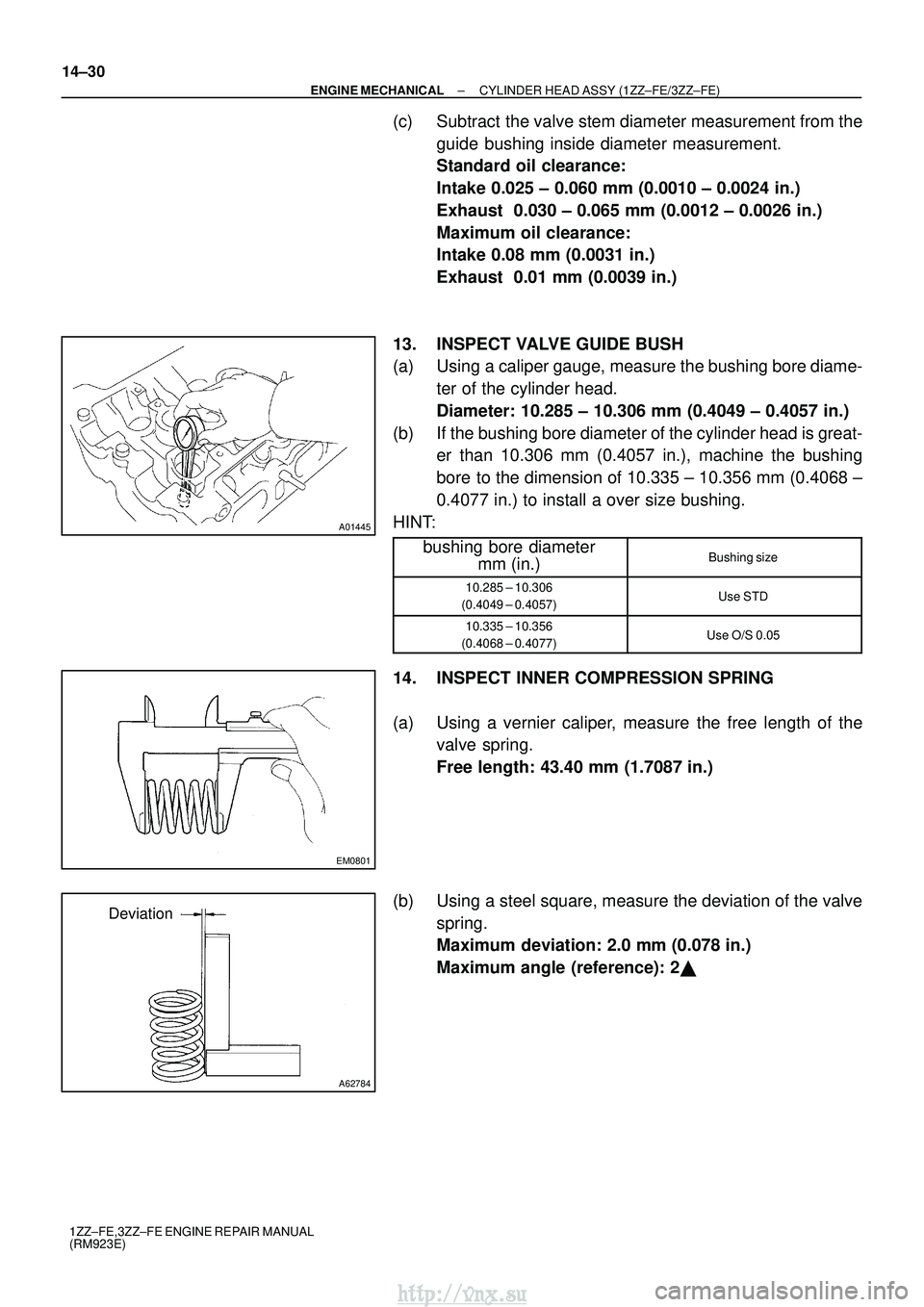
14. INSPECT INNER COMPRESSION SPRING
(a) Using a vernier caliper, measure the free length of the valve spring.
Free length: 43.40 mm (1.7087 in.)
(b) Using a steel square, measure the deviation of the valve spring.
Maximum deviation: 2.0 mm (0.078 in.)
Maximum angle (reference): 2�
http://vnx.su
Page 767 of 2234

EM2534
A62785
Margin
Thickness
EM2534
A62785
Margin
Thickness
A62786
Width
±
ENGINE MECHANICAL CYLINDER HEAD ASSY (1ZZ±FE/3ZZ±FE)
14±31
1ZZ±FE,3ZZ±FE ENGINE REPAIR MANUAL
(RM923E)
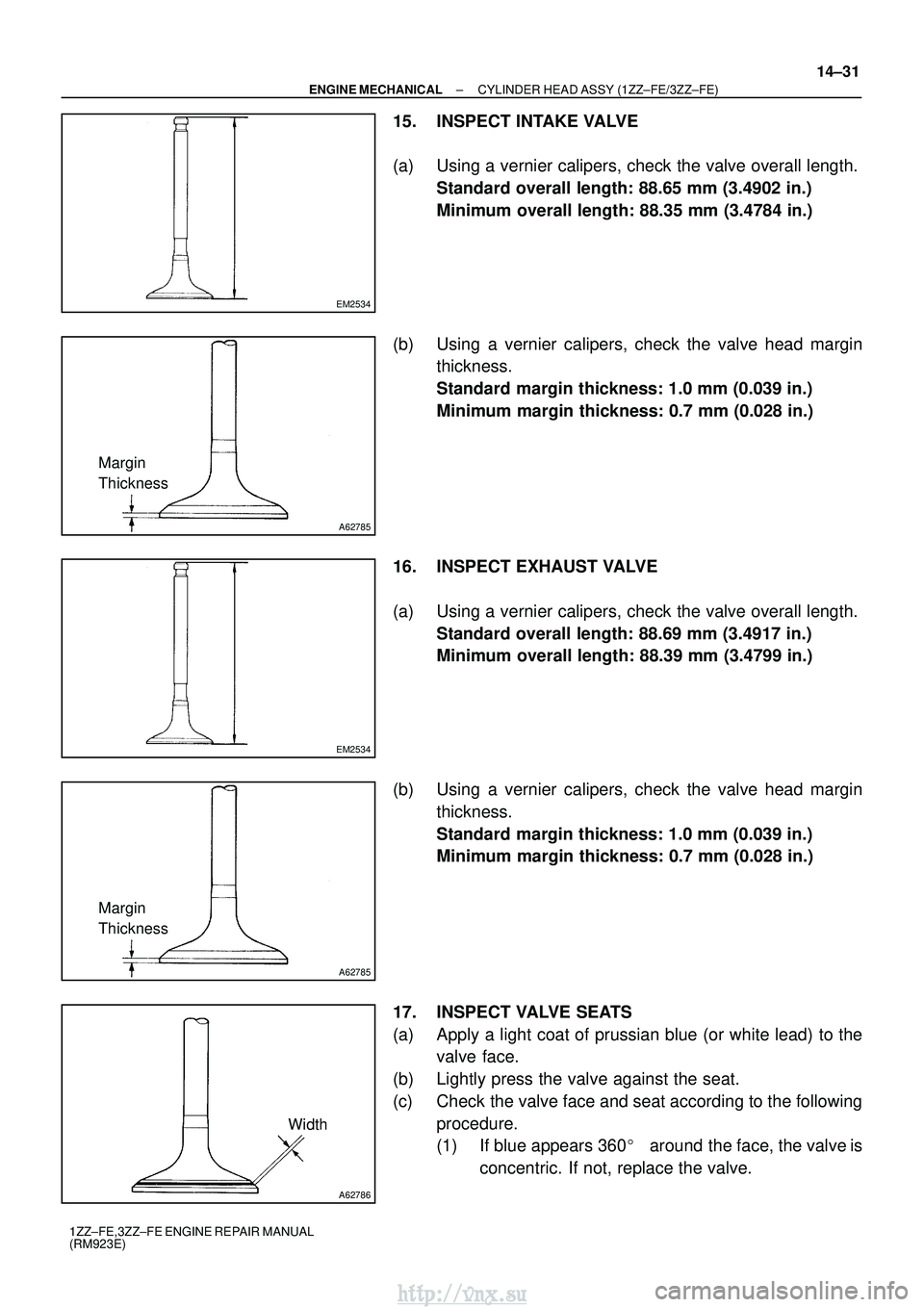
15. INSPECT INTAKE VALVE
(a) Using a vernier calipers, check the valve overall length.
Standard overall length: 88.65 mm (3.4902 in.)
Minimum overall length: 88.35 mm (3.4784 in.)
(b) Using a vernier calipers, check the valve head margin thickness.
Standard margin thickness: 1.0 mm (0.039 in.)
Minimum margin thickness: 0.7 mm (0.028 in.)
16. INSPECT EXHAUST VALVE
(a) Using a vernier calipers, check the valve overall length. Standard overall length: 88.69 mm (3.4917 in.)
Minimum overall length: 88.39 mm (3.4799 in.)
(b) Using a vernier calipers, check the valve head margin thickness.
Standard margin thickness: 1.0 mm (0.039 in.)
Minimum margin thickness: 0.7 mm (0.028 in.)
17. INSPECT VALVE SEATS
(a) Apply a light coat of prussian blue (or white lead) to the valve face.
(b) Lightly press the valve against the seat.
(c) Check the valve face and seat according to the following procedure.
(1) If blue appears 360 �around the face, the valve is
concentric. If not, replace the valve.
http://vnx.su