Page 1471 of 2234
B70206
LockUnlock
45 �
B66570
Protrusion Part
Front
Front
Mark
Protrusion Part
B66568Lock
Unlock
45�
±
SEAT BELT REAR SEAT BELT (LIFTBACK MODELS)
61±21
AVENSIS REPAIR MANUAL (RM1018E)
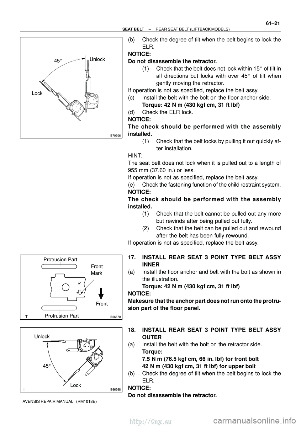
(b) Check the degree of tilt when the belt begins to lock the
ELR.
NOTICE:
Do not disassemble the retractor.
(1) Check that the belt does not lock within 15 � of tilt in
all directions but locks with over 45 � of tilt when
gently moving the retractor.
If operation is not as specified, replace the belt assy.
(c) Install the belt with the bolt on the floor anchor side. Torque: 42 N �m (430 kgf� cm, 31 ft�lbf)
(d) Check the ELR lock.
NOTICE:
The check should be performed with the a ssembly
installed. (1) Check that the belt locks by pulling it out quickly af-ter installation.
HINT:
The seat belt does not lock when it is pulled out to a length of
955 mm (37.60 in.) or less.
If operation is not as specified, replace the belt assy.
(e) Check the fastening function of the child restraint system.
NOTICE:
The check should be performed with the a ssembly
installed. (1) Check that the belt cannot be pulled out any more
but rewinds after being pulled out fully.
(2) Check that the belt can be pulled out and rewound after the belt has been fully rewound.
If operation is not as specified, replace the belt assy.
17. INSTALL REAR SEAT 3 POINT TYPE BELT ASSY
INNER
(a) Install the floor anchor and belt with the bolt as shown in the illustration.
Torque: 42 N �m (430 kgf� cm, 31 ft�lbf)
NOTICE:
Makesure that the anchor part does not run onto the protru-
sion part of the floor panel.
18. INSTALL REAR SEAT 3 POINT TYPE BELT ASSY OUTER
(a) Install the belt with the bolt on the retractor side.
Torque:
7.5 N� m (76.5 kgf� cm, 66 in.�lbf) for front bolt
42 N� m (430 kgf� cm, 31 ft�lbf) for upper bolt
(b) Check the degree of tilt when the belt begins to lock the
ELR.
NOTICE:
Do not disassemble the retractor.
http://vnx.su
Page 1475 of 2234
B70205Lock
Unlock
45�
61±16
±
SEAT BELT REAR SEAT BELT (SEDAN MODELS)
AVENSIS REPAIR MANUAL (RM1018E)
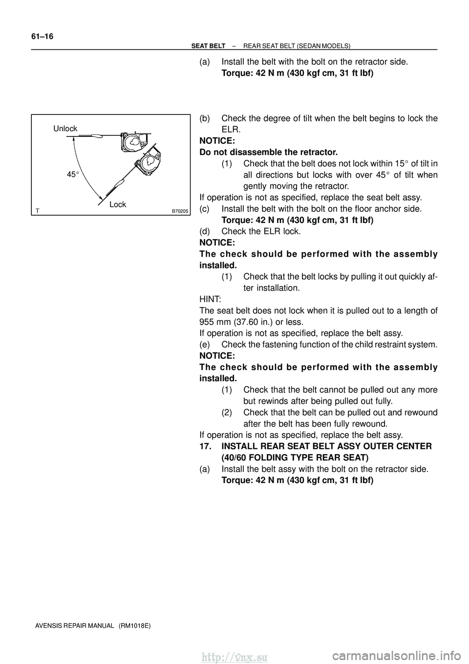
(a) Install the belt with the bolt on the retractor side. Torque: 42 N �m (430 kgf� cm, 31 ft�lbf)
(b) Check the degree of tilt when the belt begins to lock the ELR.
NOTICE:
Do not disassemble the retractor. (1) Check that the belt does not lock within 15 � of tilt in
all directions but locks with over 45 � of tilt when
gently moving the retractor.
If operation is not as specified, replace the seat belt assy.
(c) Install the belt with the bolt on the floor anchor side. Torque: 42 N �m (430 kgf� cm, 31 ft�lbf)
(d) Check the ELR lock.
NOTICE:
The check should be performed with the a ssembly
installed. (1) Check that the belt locks by pulling it out quickly af-
ter installation.
HINT:
The seat belt does not lock when it is pulled out to a length of
955 mm (37.60 in.) or less.
If operation is not as specified, replace the belt assy.
(e) Check the fastening function of the child restraint system.
NOTICE:
The check should be performed with the a ssembly
installed.
(1) Check that the belt cannot be pulled out any morebut rewinds after being pulled out fully.
(2) Check that the belt can be pulled out and rewound after the belt has been fully rewound.
If operation is not as specified, replace the belt assy.
17. INSTALL REAR SEAT BELT ASSY OUTER CENTER
(40/60 FOLDING TYPE REAR SEAT)
(a) Install the belt assy with the bolt on the retractor side. Torque: 42 N �m (430 kgf� cm, 31 ft�lbf)
http://vnx.su
Page 1476 of 2234
B70206
LockUnlock
45 �
B66570
Protrusion Part
Front
Front
Mark
Protrusion Part
B70207Lock
Unlock
45�
±
SEAT BELT REAR SEAT BELT (SEDAN MODELS)
61±17
AVENSIS REPAIR MANUAL (RM1018E)
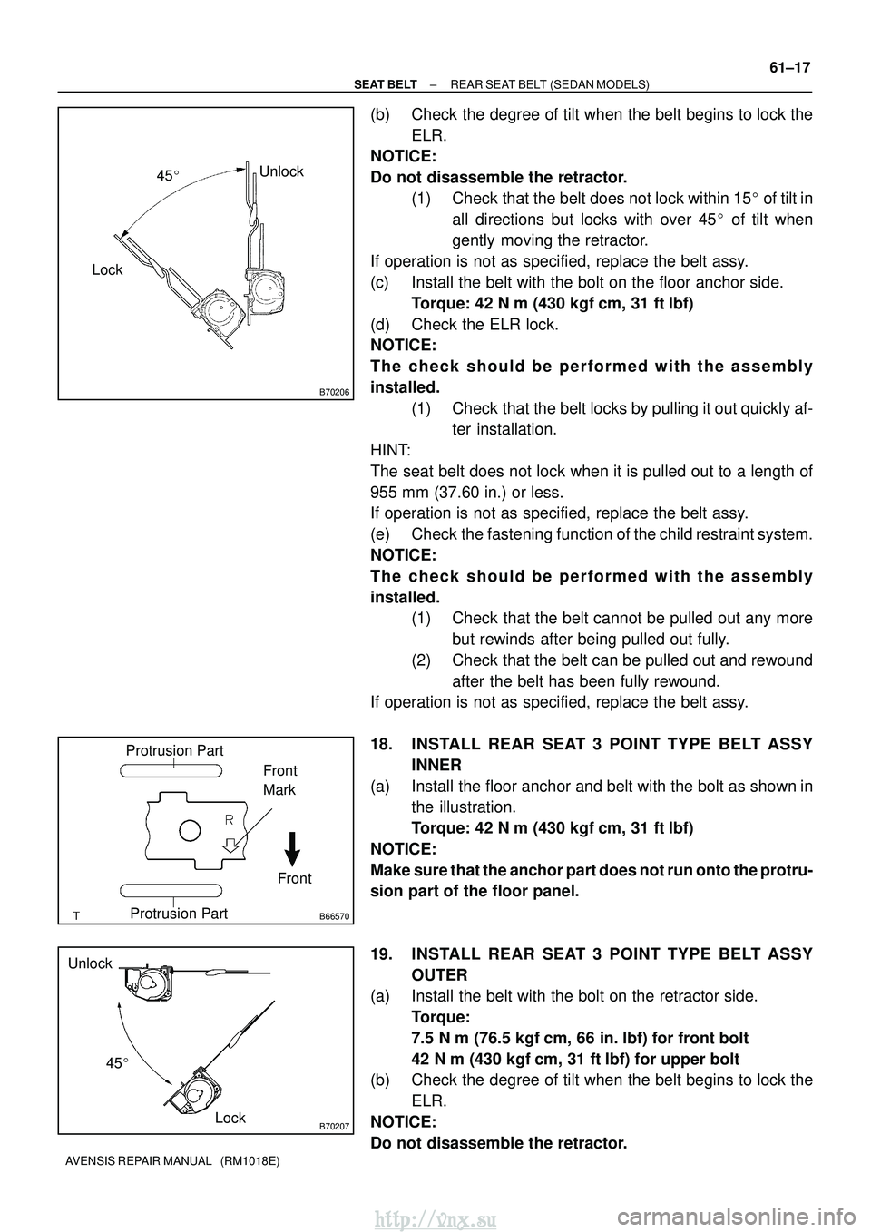
(b) Check the degree of tilt when the belt begins to lock the
ELR.
NOTICE:
Do not disassemble the retractor.
(1) Check that the belt does not lock within 15 � of tilt in
all directions but locks with over 45 � of tilt when
gently moving the retractor.
If operation is not as specified, replace the belt assy.
(c) Install the belt with the bolt on the floor anchor side. Torque: 42 N �m (430 kgf� cm, 31 ft�lbf)
(d) Check the ELR lock.
NOTICE:
The check should be performed with the a ssembly
installed. (1) Check that the belt locks by pulling it out quickly af-ter installation.
HINT:
The seat belt does not lock when it is pulled out to a length of
955 mm (37.60 in.) or less.
If operation is not as specified, replace the belt assy.
(e) Check the fastening function of the child restraint system.
NOTICE:
The check should be performed with the a ssembly
installed. (1) Check that the belt cannot be pulled out any more
but rewinds after being pulled out fully.
(2) Check that the belt can be pulled out and rewound after the belt has been fully rewound.
If operation is not as specified, replace the belt assy.
18. INSTALL REAR SEAT 3 POINT TYPE BELT ASSY
INNER
(a) Install the floor anchor and belt with the bolt as shown in the illustration.
Torque: 42 N �m (430 kgf� cm, 31 ft�lbf)
NOTICE:
Make sure that the anchor part does not run onto the protru-
sion part of the floor panel.
19. INSTALL REAR SEAT 3 POINT TYPE BELT ASSY OUTER
(a) Install the belt with the bolt on the retractor side.
Torque:
7.5 N� m (76.5 kgf� cm, 66 in.�lbf) for front bolt
42 N� m (430 kgf� cm, 31 ft�lbf) for upper bolt
(b) Check the degree of tilt when the belt begins to lock the
ELR.
NOTICE:
Do not disassemble the retractor.
http://vnx.su
Page 1480 of 2234
B70206
LockUnlock
45 �
B66570
Protrusion Part
Front
Front
Mark
Protrusion Part
B66568Lock
Unlock
45�
±
SEAT BELT REAR SEAT BELT (WAGON MODELS)
61±25
AVENSIS REPAIR MANUAL (RM1018E)
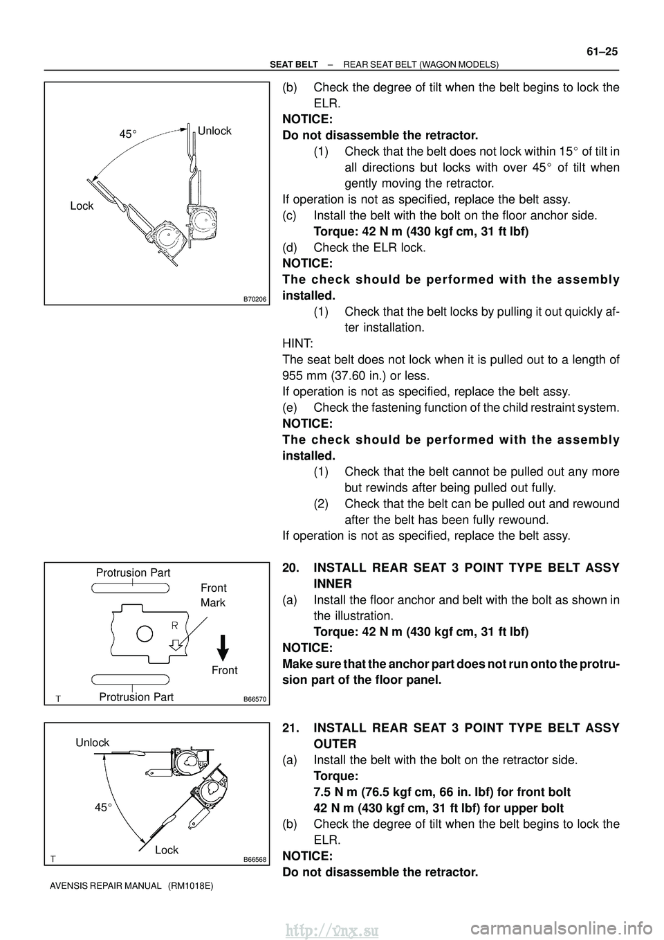
(b) Check the degree of tilt when the belt begins to lock the
ELR.
NOTICE:
Do not disassemble the retractor.
(1) Check that the belt does not lock within 15 � of tilt in
all directions but locks with over 45 � of tilt when
gently moving the retractor.
If operation is not as specified, replace the belt assy.
(c) Install the belt with the bolt on the floor anchor side. Torque: 42 N �m (430 kgf� cm, 31 ft�lbf)
(d) Check the ELR lock.
NOTICE:
The check should be performed with the a ssembly
installed. (1) Check that the belt locks by pulling it out quickly af-ter installation.
HINT:
The seat belt does not lock when it is pulled out to a length of
955 mm (37.60 in.) or less.
If operation is not as specified, replace the belt assy.
(e) Check the fastening function of the child restraint system.
NOTICE:
The check should be performed with the a ssembly
installed. (1) Check that the belt cannot be pulled out any more
but rewinds after being pulled out fully.
(2) Check that the belt can be pulled out and rewound after the belt has been fully rewound.
If operation is not as specified, replace the belt assy.
20. INSTALL REAR SEAT 3 POINT TYPE BELT ASSY
INNER
(a) Install the floor anchor and belt with the bolt as shown in the illustration.
Torque: 42 N �m (430 kgf� cm, 31 ft�lbf)
NOTICE:
Make sure that the anchor part does not run onto the protru-
sion part of the floor panel.
21. INSTALL REAR SEAT 3 POINT TYPE BELT ASSY OUTER
(a) Install the belt with the bolt on the retractor side.
Torque:
7.5 N� m (76.5 kgf� cm, 66 in.�lbf) for front bolt
42 N� m (430 kgf� cm, 31 ft�lbf) for upper bolt
(b) Check the degree of tilt when the belt begins to lock the
ELR.
NOTICE:
Do not disassemble the retractor.
http://vnx.su
Page 1607 of 2234
700TJ±01
B56435
Slide
B61414
Slide
B66957
Butyl TapeMirror Base
a
b
c
d
70±64
±
WINDSHIELD/WINDOWGLASS/MIRROR INNER REAR VIEW MIRROR ASSY
AVENSIS REPAIR MANUAL (RM1018E)
INNER REAR VIEW MIRROR ASSY
REPLACEMENT
HINT:
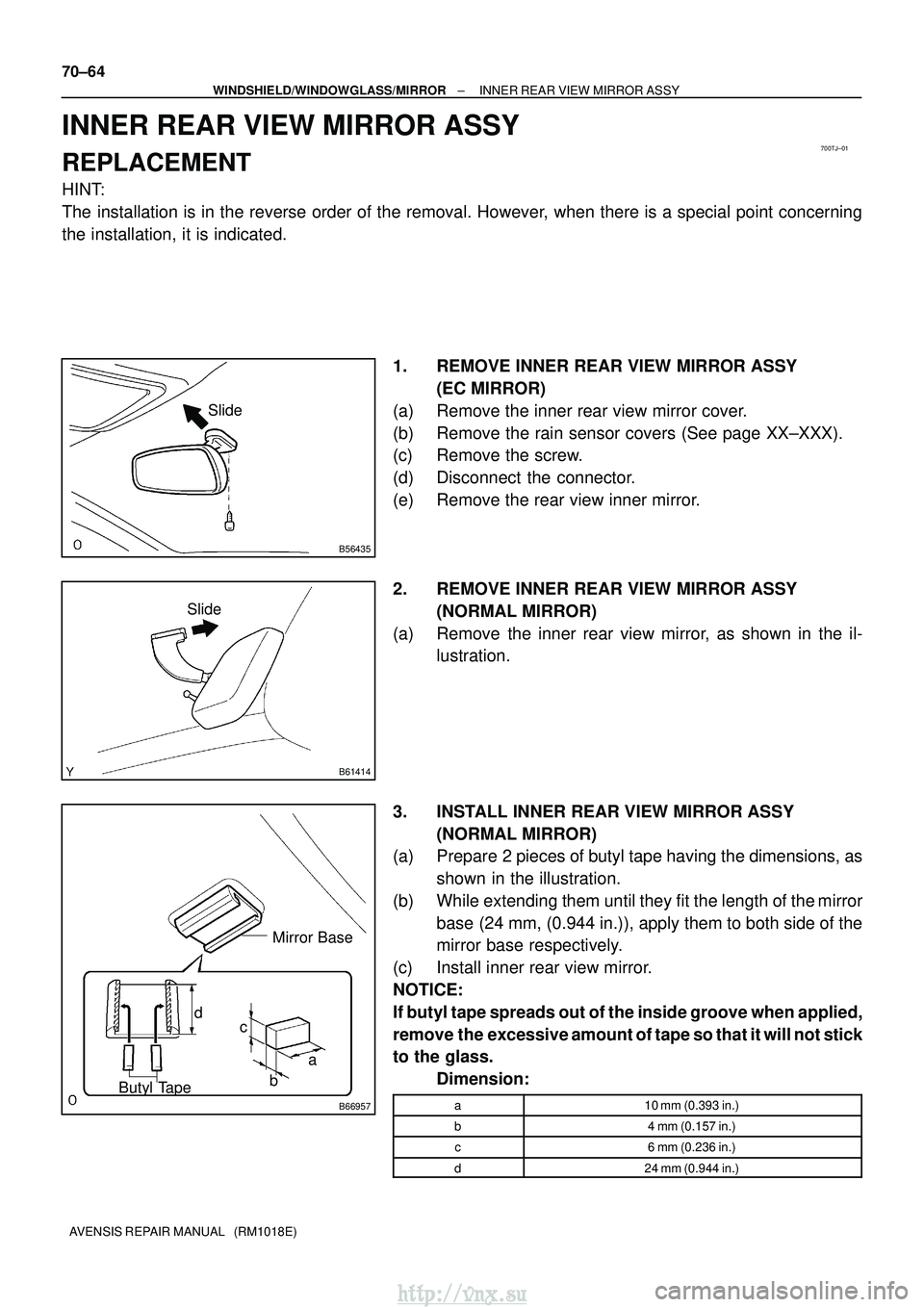
The installation is in the reverse order of the removal. However, when there is a special point concerning
the installation, it is indicated. 1. REMOVE INNER REAR VIEW MIRROR ASSY(EC MIRROR)
(a) Remove the inner rear view mirror cover.
(b) Remove the rain sensor covers (See page XX±XXX).
(c) Remove the screw.
(d) Disconnect the connector.
(e) Remove the rear view inner mirror.
2. REMOVE INNER REAR VIEW MIRROR ASSY (NORMAL MIRROR)
(a) Remove the inner rear view mirror, as shown in the il- lustration.
3. INSTALL INNER REAR VIEW MIRROR ASSY (NORMAL MIRROR)
(a) Prepare 2 pieces of butyl tape having the dimensions, as
shown in the illustration.
(b) While extending them until they fit the length of the mirror base (24 mm, (0.944 in.)), apply them to both side of the
mirror base respectively.
(c) Install inner rear view mirror.
NOTICE:
If butyl tape spreads out of the inside groove when applied,
remove the excessive amount of tape so that it will not stick
to the glass. Dimension:
a10 mm (0.393 in.)
b4 mm (0.157 in.)
c6 mm (0.236 in.)
d24 mm (0.944 in.)
http://vnx.su