Page 602 of 2234
141CP±01
CG
TCA51075
A79034
±
ENGINE MECHANICALENGINE(1AZ±FSE)
14±181
AVENSIS REPAIR MANUAL (RM1018E)
ENGINE(1AZ±FSE)
INSPECTION
1.INSPECT COOLANT (See page 16±25)
2.INSPECT ENGINE OIL(See page 17±13)
3.INSPECT BATTERY
Standard specific gravity: 1.25 to 1.29 at 20�C (68�F)
4.INSPECT AIR CLEANER FILTER ELEMENT SUB±ASSY
5.INSPECT SPARK PLUG (See page 18±14)
6.INSPECT V±RIBBED BELT
7.INSPECT IGNITION TIMING
(a)Warm up engine.
(b)When using hand±held tester:(1)Connect the hand±held tester to the DLC3.
(2)Enter DATA LIST MODE on the hand±held tester.
Ignition timing: 8 to 12� BTDC
HINT:
Please refer to the hand±held tester operator's manual if you
need help to select DATA LIST.
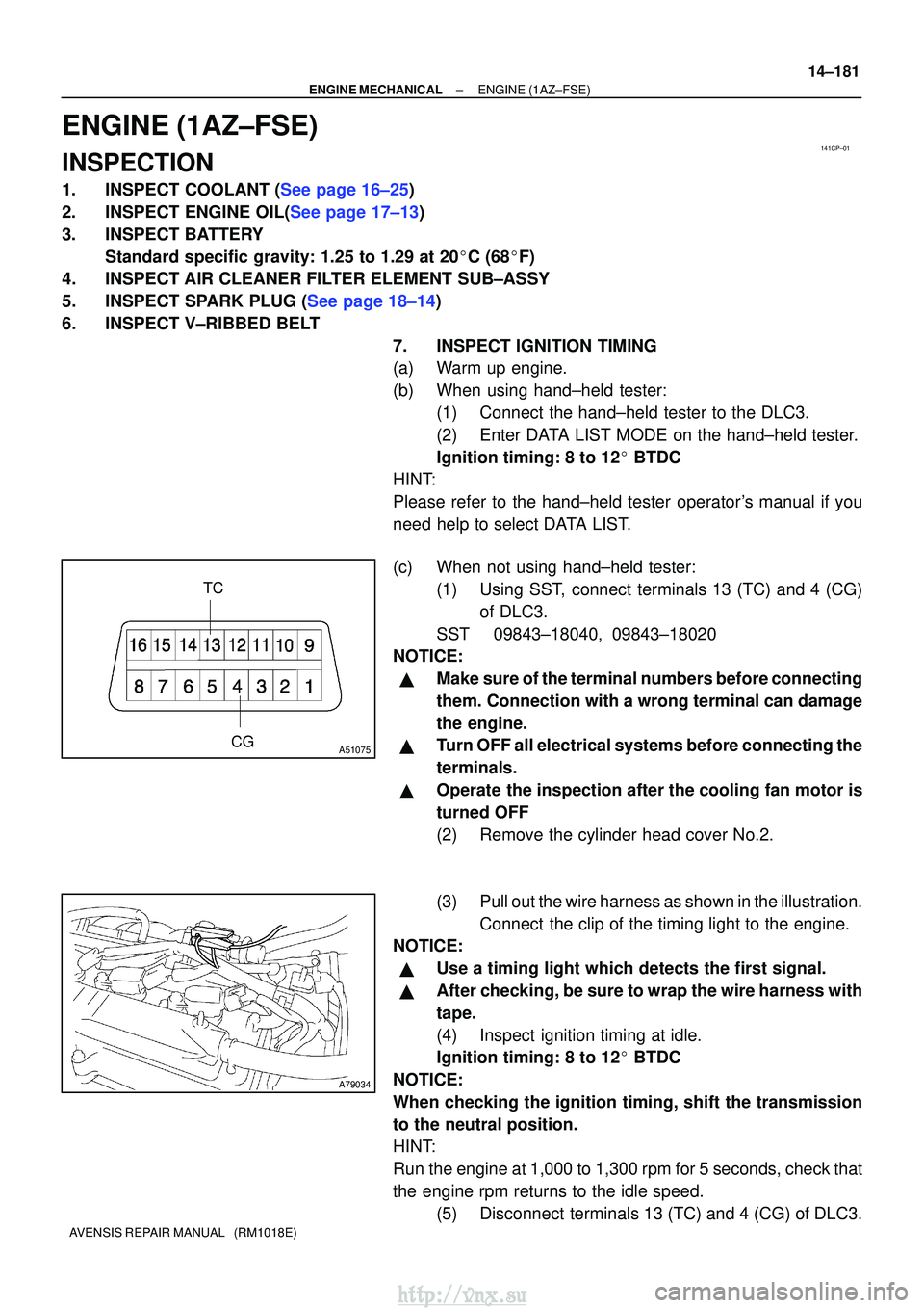
(c) When not using hand±held tester:
(1) Using SST, connect terminals 13 (TC) and 4 (CG)of DLC3.
SST 09843±18040, 09843±18020
NOTICE:
�Make sure of the terminal numbers before connecting
them. Connection with a wrong terminal can damage
the engine.
�Turn OFF all electrical systems before connecting the
terminals.
�Operate the inspection after the cooling fan motor is
turned OFF
(2) Remove the cylinder head cover No.2.
(3) Pull out the wire harness as shown in the illustration.
Connect the clip of the timing light to the engine.
NOTICE:
�Use a timing light which detects the first signal.
�After checking, be sure to wrap the wire harness with
tape.
(4) Inspect ignition timing at idle.
Ignition timing: 8 to 12 � BTDC
NOTICE:
When checking the ignition timing, shift the transmission
to the neutral position.
HINT:
Run the engine at 1,000 to 1,300 rpm for 5 seconds, check that
the engine rpm returns to the idle speed. (5) Disconnect terminals 13 (TC) and 4 (CG) of DLC3.
http://vnx.su
Page 603 of 2234
TA C
A52006
14±182
±
ENGINE MECHANICAL ENGINE (1AZ±FSE)
AVENSIS REPAIR MANUAL (RM1018E)
(6) Inspect ignition timing at idle.
Ignition timing: 5 to 23 � BTDC
(7) Confirm that ignition timing to go advanced angle
side when the engine rpm is increased.
(8) Remove the timing light.
8. INSPECT ENGINE IDLE SPEED
(a) Warm up engine.
(b) When using hand±held tester: (1) Connect the hand±held tester to the DLC3.
Idle speed: 625 to 725 rpm
NOTICE:
�Check the idle speed with the cooling fan OFF.
�Switch off all accessories and air conditioning before
connecting the test prove to the terminal.
HINT:
Please refer to the hand±held tester operator's manual if you
need help to select DATA LIST.
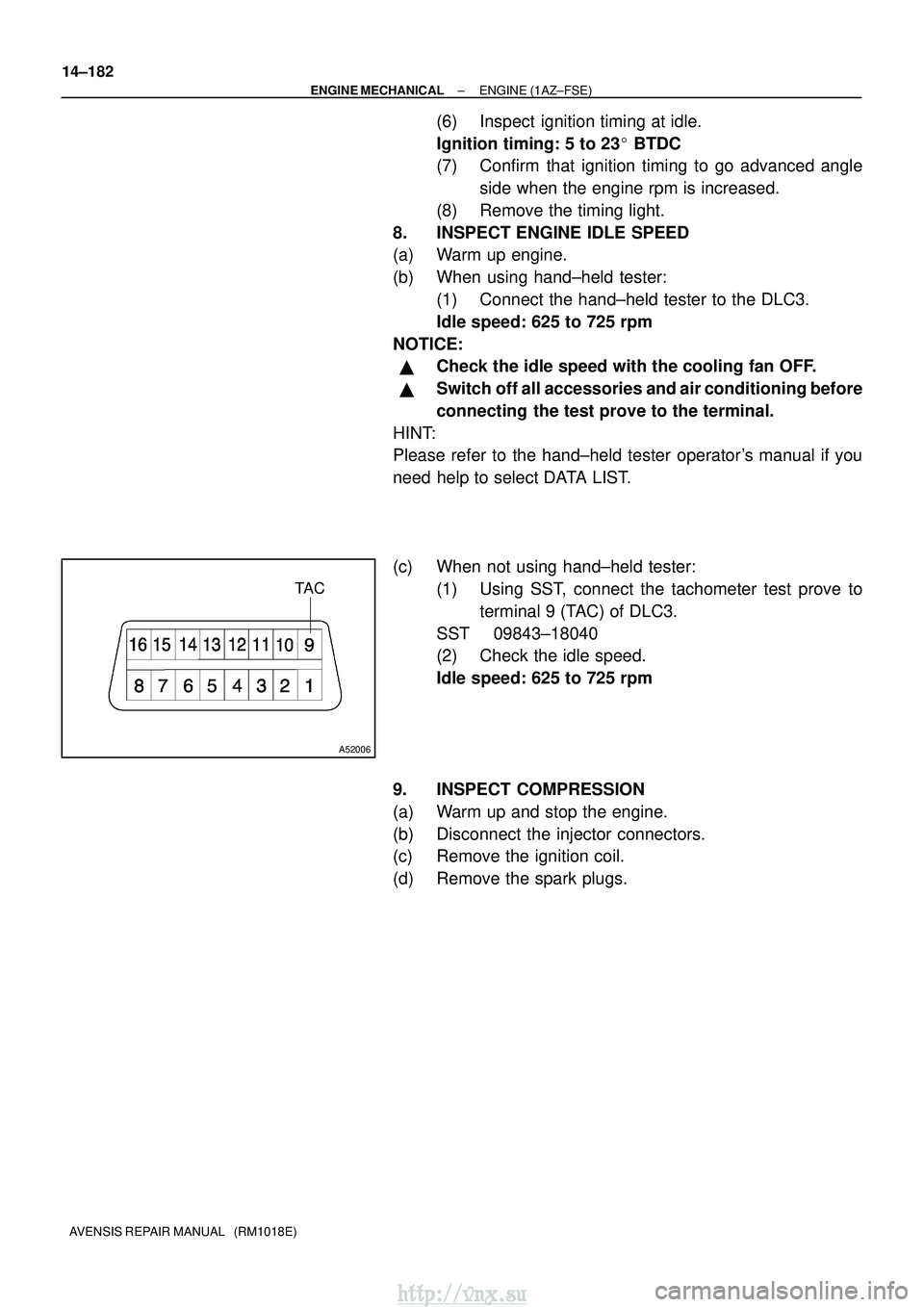
(c) When not using hand±held tester: (1) Using SST, connect the tachometer test prove toterminal 9 (TAC) of DLC3.
SST 09843±18040
(2) Check the idle speed.
Idle speed: 625 to 725 rpm
9. INSPECT COMPRESSION
(a) Warm up and stop the engine.
(b) Disconnect the injector connectors.
(c) Remove the ignition coil.
(d) Remove the spark plugs.
http://vnx.su
Page 609 of 2234
140KR±02
A62199
TCCG
A62200
±
ENGINE MECHANICALENGINE(1ZZ±FE/3ZZ±FE)
14±1
AVENSIS REPAIR MANUAL (RM1018E)
ENGINE(1ZZ±FE/3ZZ±FE)
INSPECTION
1.INSPECT COOLANT (See page 16±1)
2.INSPECT ENGINE OIL (See page 17±1)
3.INSPECT BATTERY (See page 19±5)
4.INSPECT AIR CLEANER FILTER ELEMENT SUB±ASSY
5.INSPECT SPARK PLUG (See page 18±3)
6.INSPECT FAN AND GENERATOR V BELT
HINT:
You don't need to check the belt deflection because auto tensioner is ado\
pted.
7.INSPECT IGNITION TIMING
(a)Warm up engine.
(b)When using hand±held tester:
(1)Connect the hand±held tester to the DLC3.
(2)Enter DATA LIST MODE on the hand±held tester.
Ignition timing: 8 to 12�BTDC
HINT:
Please refer to the hand±held tester operator's manual if you
need help to select DATA LIST.
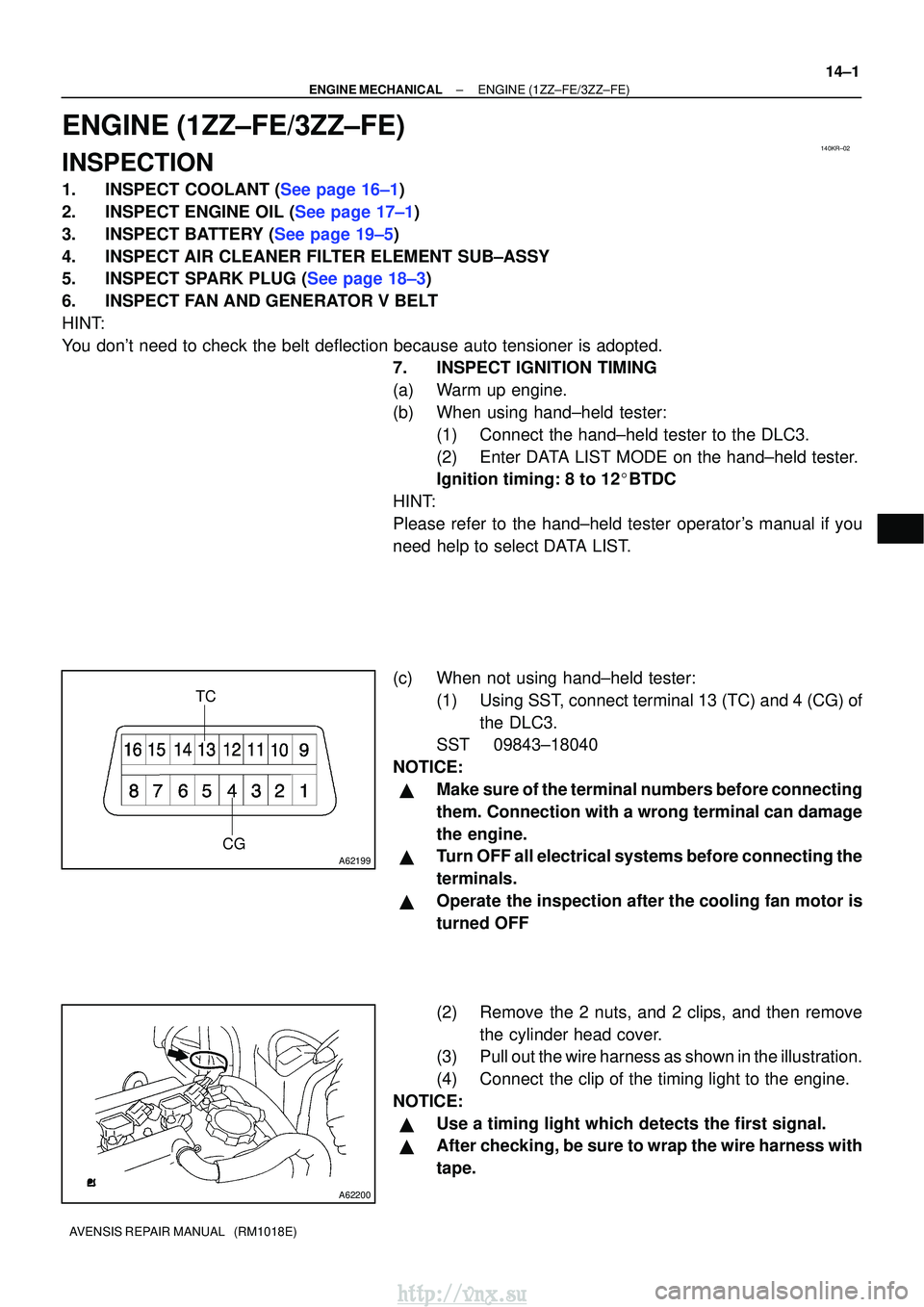
(c) When not using hand±held tester: (1) Using SST, connect terminal 13 (TC) and 4 (CG) ofthe DLC3.
SST 09843±18040
NOTICE:
�Make sure of the terminal numbers before connecting
them. Connection with a wrong terminal can damage
the engine.
�Turn OFF all electrical systems before connecting the
terminals.
�Operate the inspection after the cooling fan motor is
turned OFF
(2) Remove the 2 nuts, and 2 clips, and then remove the cylinder head cover.
(3) Pull out the wire harness as shown in the illustration.
(4) Connect the clip of the timing light to the engine.
NOTICE:
�Use a timing light which detects the first signal.
�After checking, be sure to wrap the wire harness with
tape.
http://vnx.su
Page 610 of 2234
TA C
A52006
A01037
14±2
±
ENGINE MECHANICAL ENGINE (1ZZ±FE/3ZZ±FE)
AVENSIS REPAIR MANUAL (RM1018E)
(5) Inspect ignition timing at idle.
Ignition timing: 8 to 12 �BTDC
NOTICE:
When checking the ignition timing, shift the transmission
to the neutral position.
HINT:
Run the engine at 1,000 to 1,300 rpm for 5 seconds, check that
the engine rpm returns to the idle speed.
(6) Disconnect the terminal 13 (TC) and 4 (CG) of theDLC3.
(7) Inspect ignition timing at idle.
Ignition timing:
10 to 18 �BTDC (1ZZ±FE)
3.5 to 11.5 �BTDC (3ZZ±FE)
(8) Confirm that ignition timing to go advanced angle side when the engine rpm is increased.
(9) Remove the timing light.
(10) Install the cylinder head cover with the 2 nuts and 2 clips.
Torque: 7.0 N �m (71 kgf �cm, 62 in. �lbf)
8. INSPECT ENGINE IDLE SPEED
(a) Warm up engine.
(b) When using hand±held tester: (1) Connect the hand±held tester to the DLC3.
HINT:
Please refer to the hand±held tester operator's manual if you
need help to select DATA LIST.
(c) When not using hand±held tester:
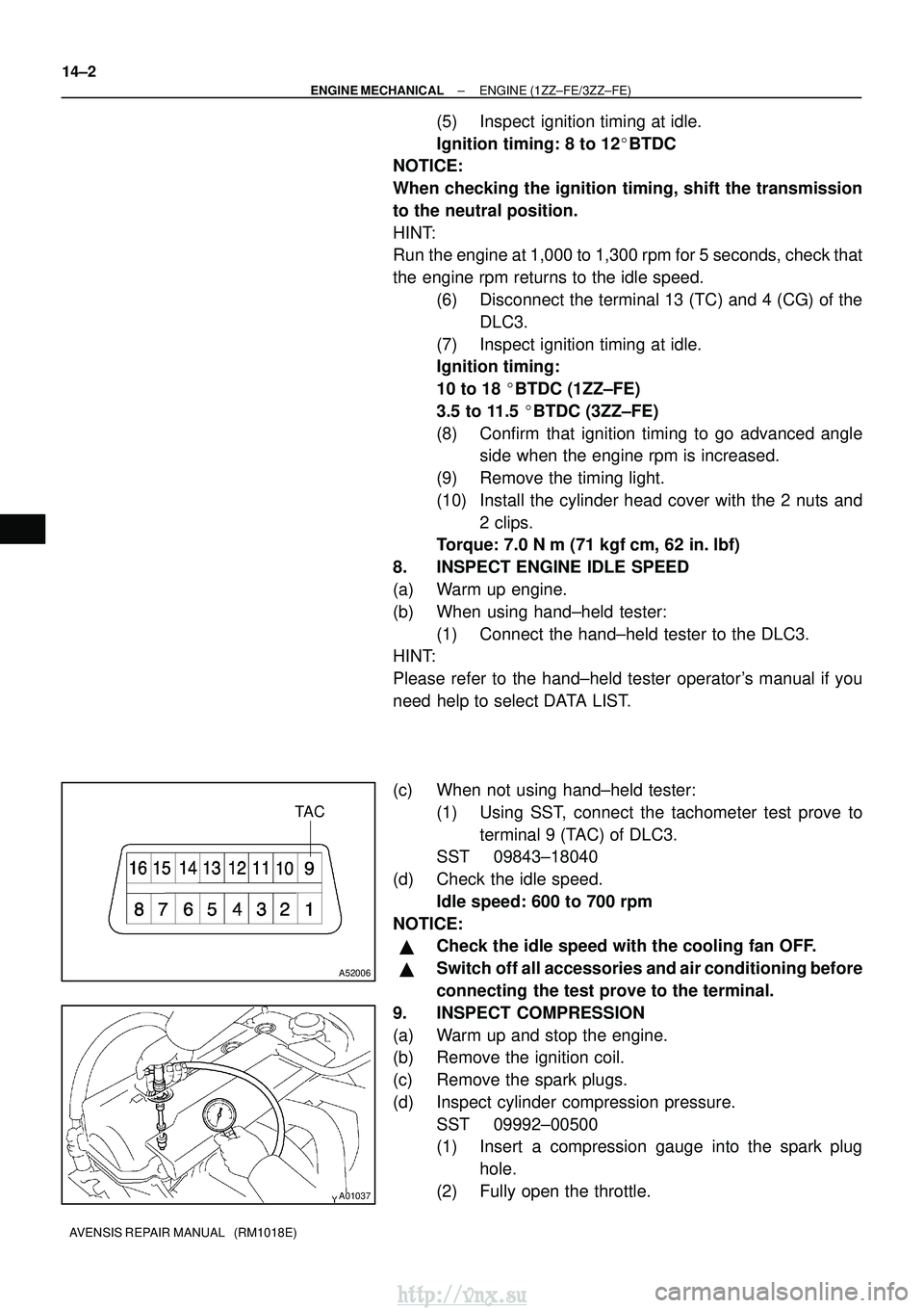
(1) Using SST, connect the tachometer test prove toterminal 9 (TAC) of DLC3.
SST 09843±18040
(d) Check the idle speed. Idle speed: 600 to 700 rpm
NOTICE:
�Check the idle speed with the cooling fan OFF.
�Switch off all accessories and air conditioning before
connecting the test prove to the terminal.
9. INSPECT COMPRESSION
(a) Warm up and stop the engine.
(b) Remove the ignition coil.
(c) Remove the spark plugs.
(d) Inspect cylinder compression pressure. SST 09992±00500
(1) Insert a compression gauge into the spark plughole.
(2) Fully open the throttle.
http://vnx.su
Page 642 of 2234
A52499
A56446
A77333SST
14±130
±
ENGINE MECHANICAL PARTIAL ENGINE ASSY (1AZ±FE)
AVENSIS REPAIR MANUAL (RM1018E)
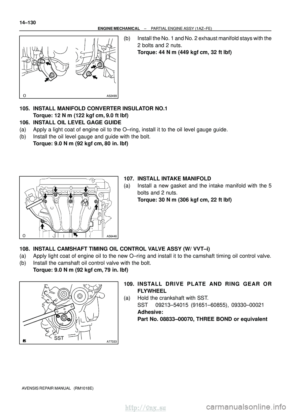
(b) Install the No. 1 and No. 2 exhaust manifold stays with the 2 bolts and 2 nuts.
Torque: 44 N �m (449 kgf� cm, 32 ft�lbf)
105. INSTALL MANIFOLD CONVERTER INSULATOR NO.1 Torque: 12 N �m (122 kgf� cm, 9.0 ft�lbf)
106. INSTALL OIL LEVEL GAGE GUIDE
(a) Apply a light coat of engine oil to the O±ring, install it to the oil\
level gauge guide.
(b) Install the oil level gauge and guide with the bolt. Torque: 9.0 N �m (92 kgf �cm, 80 in. �lbf)
107. INSTALL INTAKE MANIFOLD
(a) Install a new gasket and the intake manifold with the 5 bolts and 2 nuts.
Torque: 30 N �m (306 kgf� cm, 22 ft�lbf)
108. INSTALL CAMSHAFT TIMING OIL CONTROL VALVE ASSY (W/ VVT±i)
(a) Apply light coat of engine oil to the new O±ring and install it to th\
e camshaft timing oil control valve.
(b) Install the camshaft oil control valve with the bolt. Torque: 9.0 N �m (92 kgf �cm, 79 in. �lbf)
109. I N S TA L L D R I V E P L AT E A N D R I N G G E A R O R FLYWHEEL
(a) Hold the crankshaft with SST.
SST 09213±54015 (91651±60855), 09330±00021
Adhesive:
Part No. 08833±00070, THREE BOND or equivalent
http://vnx.su
Page 695 of 2234
A64060
A64059
A79324
A76692
B00084
±
ENGINE MECHANICAL PARTIAL ENGINE ASSY (1ZZ±FE/3ZZ±FE)
14±39
AVENSIS REPAIR MANUAL (RM1018E)
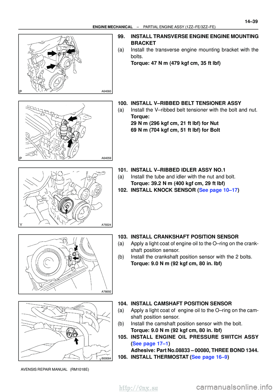
99. INSTALL TRANSVERSE ENGINE ENGINE MOUNTING
BRACKET
(a) Install the transverse engine mounting bracket with the
bolts.
Torque: 47 N� m (479 kgf�cm, 35 ft�lbf)
100. INSTALL V±RIBBED BELT TENSIONER ASSY
(a) Install the V±ribbed belt tensioner with the bolt and nut. Torque:
29 N�m (296 kgf� cm, 21 ft�lbf) for Nut
69 N� m (704 kgf� cm, 51 ft�lbf) for Bolt
101. INSTALL V±RIBBED IDLER ASSY NO.1
(a) Install the tube and idler with the nut and bolt. Torque: 39.2 N� m (400 kgf�cm, 29 ft�lbf)
102.INSTALL KNOCK SENSOR (See page 10±17)
103. INSTALL CRANKSHAFT POSITION SENSOR
(a) Apply a light coat of engine oil to the O±ring on the crank- shaft position sensor.
(b) Install the crankshaft position sensor with the 2 bolts.
Torque: 9.0 N �m (92 kgf �cm, 80 in. �lbf)
104. INSTALL CAMSHAFT POSITION SENSOR
(a) Apply a light coat of engine oil to the O±ring on the cam- shaft position sensor.
(b) Install the camshaft position sensor with the bolt. Torque: 9.0 N �m (92 kgf �cm, 80 in. �lbf)
105. INSTALL ENGINE OIL PR ESSURE SWITCH ASSY
(See page 17±1)
Adhesive: Part No.08833 ± 00080, THREE BOND 1344.
106.INSTALL THERMOSTAT(See page 16±9)
http://vnx.su
Page 696 of 2234
A64028
A64027
A64026
A79363
A64023
14±40
±
ENGINE MECHANICAL PARTIAL ENGINE ASSY (1ZZ±FE/3ZZ±FE)
AVENSIS REPAIR MANUAL (RM1018E)
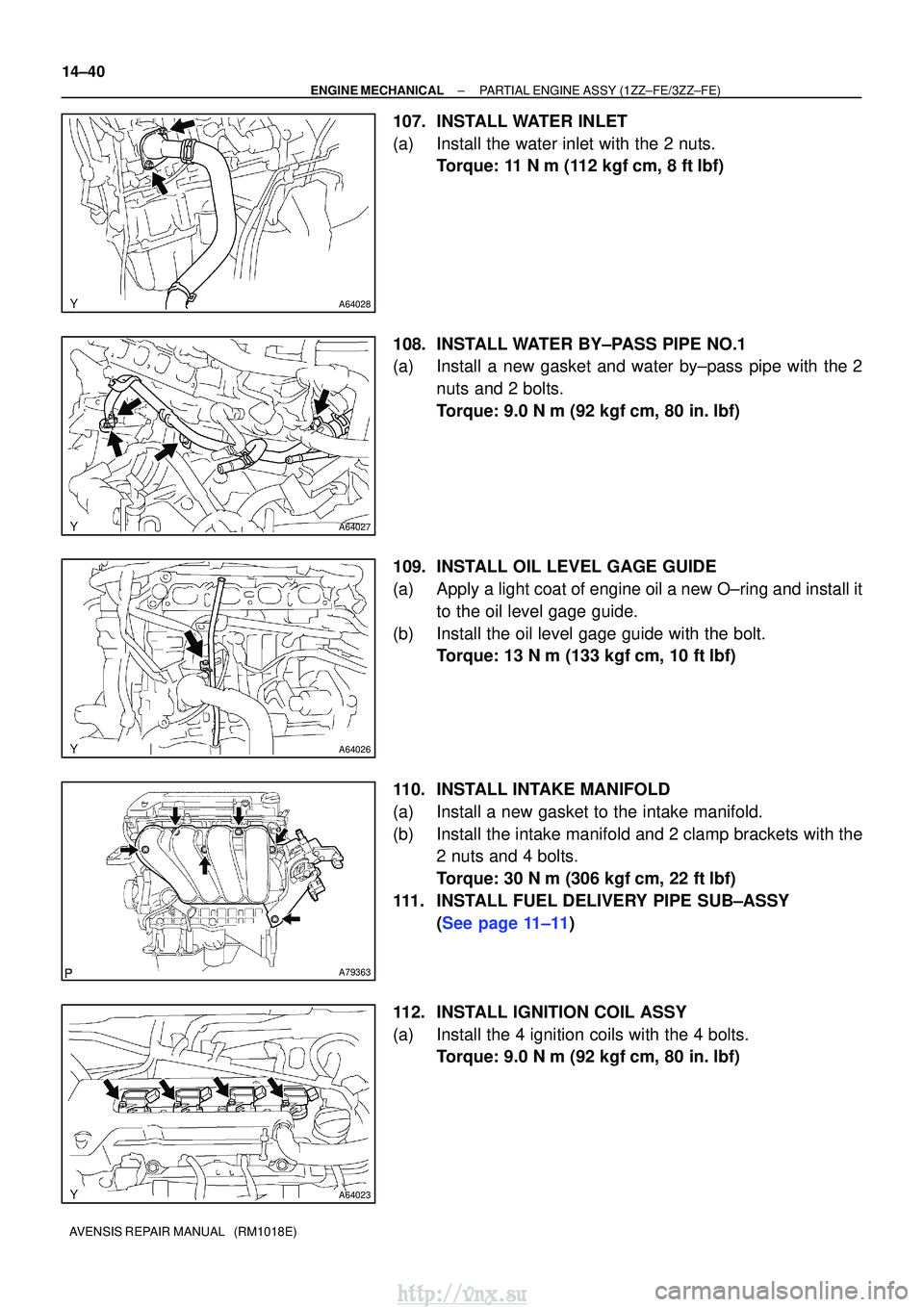
107. INSTALL WATER INLET
(a) Install the water inlet with the 2 nuts. Torque: 11 N� m (112 kgf�cm, 8 ft� lbf)
108. INSTALL WATER BY±PASS PIPE NO.1
(a) Install a new gasket and water by±pass pipe with the 2 nuts and 2 bolts.
Torque: 9.0 N �m (92 kgf �cm, 80 in. �lbf)
109. INSTALL OIL LEVEL GAGE GUIDE
(a) Apply a light coat of engine oil a new O±ring and install it to the oil level gage guide.
(b) Install the oil level gage guide with the bolt. Torque: 13 N �m (133 kgf� cm, 10 ft�lbf)
110. INSTALL INTAKE MANIFOLD
(a) Install a new gasket to the intake manifold.
(b) Install the intake manifold and 2 clamp brackets with the 2 nuts and 4 bolts.
Torque: 30 N �m (306 kgf� cm, 22 ft�lbf)
111. INSTALL FUEL DELIVERY PIPE SUB±ASSY (See page 11±11)
112. INSTALL IGNITION COIL ASSY
(a) Install the 4 ignition coils with the 4 bolts. Torque: 9.0 N �m (92 kgf �cm, 80 in. �lbf)
http://vnx.su
Page 749 of 2234
A01163
A62798
Paint Mark
90
�
Front
A01160
A62799
Mark
1, 2 or 3
A01166
14±40
±
ENGINE MECHANICAL CYLINDER BLOCK (1ZZ±FE/3ZZ±FE)
1ZZ±FE,3ZZ±FE ENGINE REPAIR MANUAL
(RM923E)
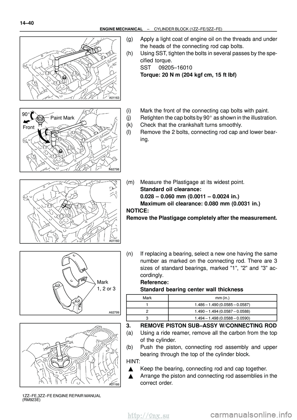
(g) Apply a light coat of engine oil on the threads and under the heads of the connecting rod cap bolts.
(h) Using SST, tighten the bolts in several passes by the spe-
cified torque.
SST 09205±16010
Torque: 20 N �m (204 kgf� cm, 15 ft�lbf)
(i) Mark the front of the connecting cap bolts with paint.
(j) Retighten the cap bolts by 90 � as shown in the illustration.
(k) Check that the crankshaft turns smoothly.
(l) Remove the 2 bolts, connecting rod cap and lower bear- ing.
(m) Measure the Plastigage at its widest point. Standard oil clearance:
0.028 ± 0.060 mm (0.0011 ± 0.0024 in.)
Maximum oil clearance: 0.080 mm (0.0031 in.)
NOTICE:
Remove the Plastigage completely after the measurement.
(n) If replacing a bearing, select a new one having the same
number as marked on the connecting rod. There are 3
sizes of standard bearings, marked º1º, º2º and º3º ac\
-
cordingly.
Reference:
Standard bearing center wall thickness
Markmm (in.)
11.486 ± 1.490 (0.0585 ± 0.0587)
21.490 ± 1.494 (0.0587 ± 0.0588)
31.494 ± 1.498 (0.0588 ± 0.0590)
3. REMOVE PISTON SUB±ASSY W/CONNECTING ROD
(a) Using a ride reamer, remove all the carbon from the topof the cylinder.
(b) Push the piston, connecting rod assembly and upper
bearing through the top of the cylinder block.
HINT:
�Keep the bearing, connecting rod and cap together.
�Arrange the piston and connecting rod assemblies in the
correct order.
http://vnx.su