Page 281 of 2234
A60552
30
20
105
3
2
1
0.5
0.3
0.2
0.1
RESISTANCE k�
±20 0 20 40 60 80 100 (±4)
TEMPERATURE �C( �F)
(32) (68) (104)(140)(176)(212)
A65174
Ohmmeter
A60553
±
ENGINE CONTROL SYSTEM SFI SYSTEM (1ZZ±FE/3ZZ±FE)
10±5
AVENSIS REPAIR MANUAL (RM1018E)
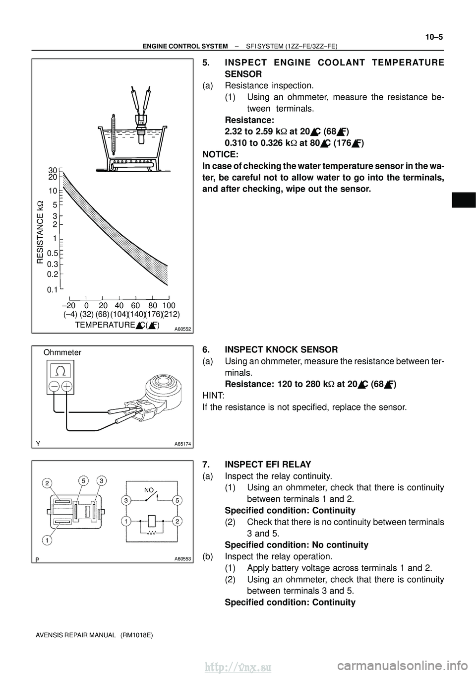
5. INSPECT ENGINE COOLANT TEMPERA TURE
SENSOR
(a) Resistance inspection.
(1) Using an ohmmeter, measure the resistance be-tween terminals.
Resistance:
2.32 to 2.59 k �at 20� C (68� F)
0.310 to 0.326 k �at 80� C (176� F)
NOTICE:
In case of checking the water temperature sensor in the wa-
ter, be careful not to allow water to go into the terminals,
and after checking, wipe out the sensor.
6. INSPECT KNOCK SENSOR
(a) Using an ohmmeter, measure the resistance between ter- minals.
Resistance: 120 to 280 k �at 20� C (68� F)
HINT:
If the resistance is not specified, replace the sensor.
7. INSPECT EFI RELAY
(a) Inspect the relay continuity. (1) Using an ohmmeter, check that there is continuity
between terminals 1 and 2.
Specified condition: Continuity
(2) Check that there is no continuity between terminals 3 and 5.
Specified condition: No continuity
(b) Inspect the relay operation. (1) Apply battery voltage across terminals 1 and 2.
(2) Using an ohmmeter, check that there is continuitybetween terminals 3 and 5.
Specified condition: Continuity
http://vnx.su
Page 287 of 2234
100FH±01
A778975 Claws
A77902
A77872
10±26
±
ENGINE CONTROL SYSTEMTHROTTLE BODY ASSY(1AZ±FE)
AVENSIS REPAIR MANUAL (RM1018E)
Removal & Installation and Disassembly & Reassembly
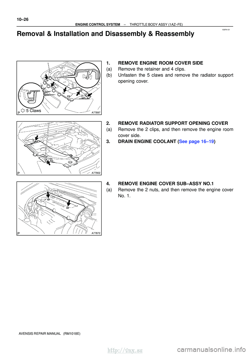
1.REMOVE ENGINE ROOM COVER SIDE
(a)Remove the retainer and 4 clips.
(b)Unfasten the 5 claws and remove the radiator support opening cover.
2.REMOVE RADIATOR SUPPORT OPENING COVER
(a)Remove the 2 clips, and then remove the engine room cover side.
3.DRAIN ENGINE COOLANT (See page 16±19)
4. REMOVE ENGINE COVER SUB±ASSY NO.1
(a) Remove the 2 nuts, and then remove the engine cover No. 1.
http://vnx.su
Page 290 of 2234
A77879
45�
A77880
83.8 mm
(3.299 in.)
Rotation
Center of
Throttle Link
±
ENGINE CONTROL SYSTEMTHROTTLE BODY ASSY(1AZ±FE)
10±29
AVENSIS REPAIR MANUAL (RM1018E)
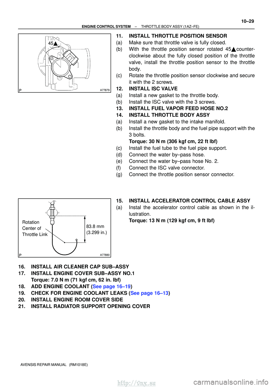
11.INSTALL THROTTLE POSITION SENSOR
(a)Make sure that throttle valve is fully closed.
(b)With the throttle position sensor rotated 45� counter-
clockwise about the fully closed position of the throttle
valve, install the throttle position sensor to the throttle
body.
(c)Rotate the throttle position sensor clockwise and secure
it with the 2 screws.
12.INSTALL ISC VALVE
(a)Install a new gasket to the throttle body.
(b)Install the ISC valve with the 3 screws.
13.INSTALL FUEL VAPOR FEED HOSE NO.2
14.INSTALL THROTTLE BODY ASSY
(a)Install a new gasket to the intake manifold.
(b)Install the throttle body and the fuel pipe support with the 3 bolts.
Torque: 30 N �m (306 kgf�cm, 22 ft�lbf)
(c)Install the fuel tube to the fuel pipe support.
(d)Connect the water by±pass hose.
(e)Connect the water by±pass hose No. 2.
(f)Connect the ISC valve connector.
(g)Connect the throttle position sensor connector.
15.INSTALL ACCELERATOR CONTROL CABLE ASSY
(a)Instal the accelerator control cable as shown in the il- lustration.
Torque: 13 N�m (129 kgf�cm, 9 ft�lbf)
16.INSTALL AIR CLEANER CAP SUB±ASSY
17.INSTALL ENGINE COVER SUB±ASSY NO.1 Torque: 7.0 N �m (71 kgf�cm, 62 in. �lbf)
18.ADD ENGINE COOLANT (See page 16±19)
19.CHECK FOR ENGINE COOLANT LEAKS (See page 16±13)
20. INSTALL ENGINE ROOM COVER SIDE
21. INSTALL RADIATOR SUPPORT OPENING COVER
http://vnx.su
Page 293 of 2234
100FJ±01
A78509
A81620
(a)(c)
(c)
(b)
(d)
(f)
(g)
(d)
(h)
Air Cleaner Clamp
A78510
10±44
±
ENGINE CONTROL SYSTEMTHROTTLE BODY ASSY(1AZ±FSE)
AVENSIS REPAIR MANUAL (RM1018E)
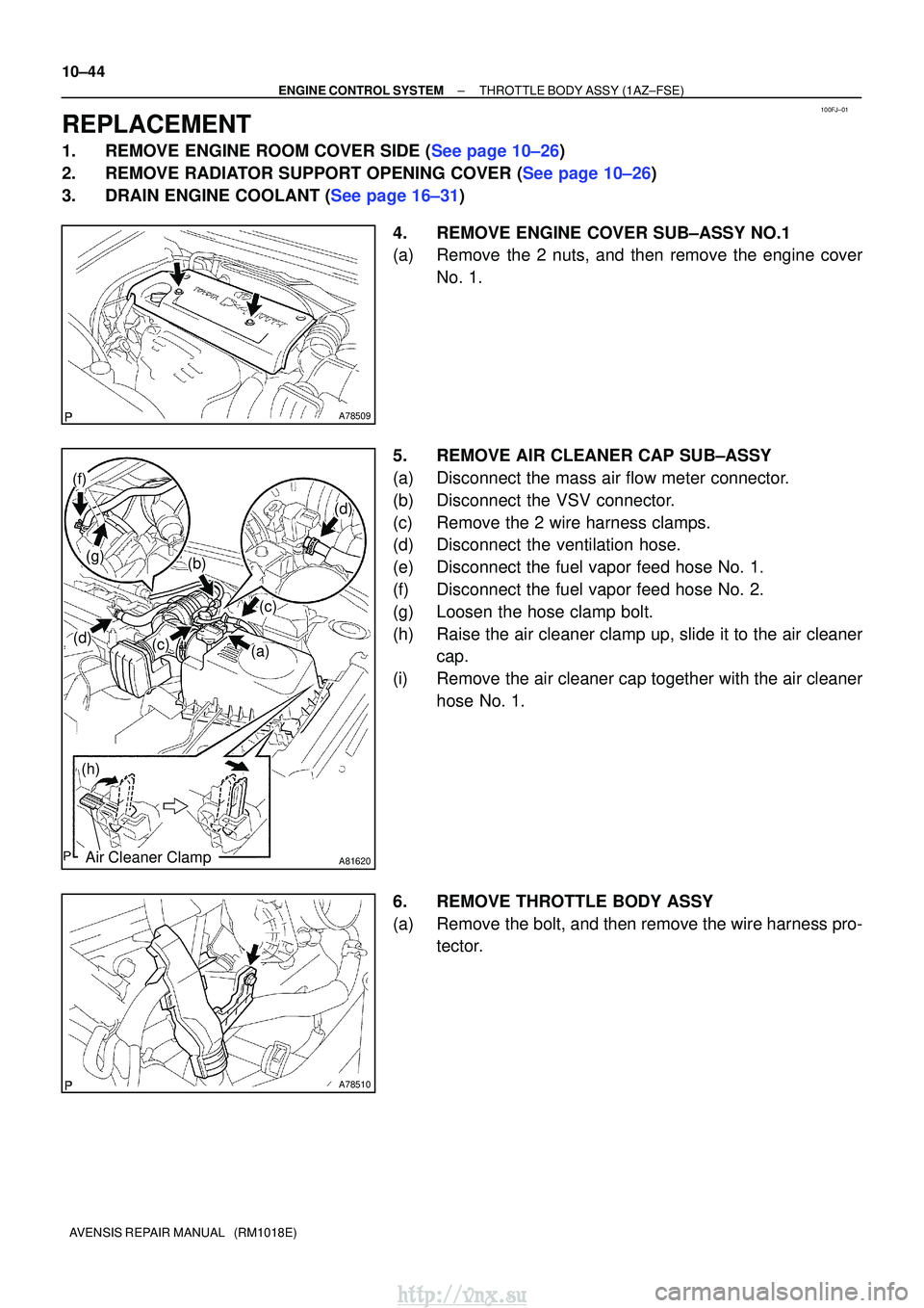
REPLACEMENT
1.REMOVE ENGINE ROOM COVER SIDE (See page 10±26)
2.REMOVE RADIATOR SUPPORT OPENING COVER (See page 10±26)
3.DRAIN ENGINE COOLANT (See page 16±31) 4. REMOVE ENGINE COVER SUB±ASSY NO.1
(a) Remove the 2 nuts, and then remove the engine coverNo. 1.
5. REMOVE AIR CLEANER CAP SUB±ASSY
(a) Disconnect the mass air flow meter connector.
(b) Disconnect the VSV connector.
(c) Remove the 2 wire harness clamps.
(d) Disconnect the ventilation hose.
(e) Disconnect the fuel vapor feed hose No. 1.
(f) Disconnect the fuel vapor feed hose No. 2.
(g) Loosen the hose clamp bolt.
(h) Raise the air cleaner clamp up, slide it to the air cleaner cap.
(i) Remove the air cleaner cap together with the air cleaner hose No. 1.
6. REMOVE THROTTLE BODY ASSY
(a) Remove the bolt, and then remove the wire harness pro- tector.
http://vnx.su
Page 294 of 2234
A78511
(b)
A78512
(d)
A78513
(g)
(h)
±
ENGINE CONTROL SYSTEMTHROTTLE BODY ASSY(1AZ±FSE)
10±45
AVENSIS REPAIR MANUAL (RM1018E)
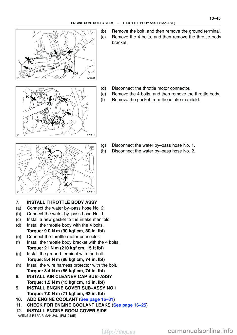
(b)Remove the bolt, and then remove the ground terminal.
(c)Remove the 4 bolts, and then remove the throttle body
bracket.
(d)Disconnect the throttle motor connector.
(e)Remove the 4 bolts, and then remove the throttle body.
(f)Remove the gasket from the intake manifold.
(g)Disconnect the water by±pass hose No. 1.
(h)Disconnect the water by±pass hose No. 2.
7.INSTALL THROTTLE BODY ASSY
(a)Connect the water by±pass hose No. 2.
(b)Connect the water by±pass hose No. 1.
(c)Install a new gasket to the intake manifold.
(d)Install the throttle body with the 4 bolts. Torque: 9.0 N �m (90 kgf�cm, 80 in. �lbf)
(e)Connect the throttle motor connector.
(f)Install the throttle body bracket with the 4 bolts. Torque: 21 N �m (210 kgf�cm, 15 ft�lbf)
(g)Install the ground terminal with the bolt. Torque: 8.4 N �m (86 kgf�cm, 74 in. �lbf)
(h)Install the wire harness protector with the bolt. Torque: 8.4 N �m (86 kgf�cm, 74 in. �lbf)
8.INSTALL AIR CLEANER CAP SUB±ASSY Torque: 1.5 N �m (15 kgf�cm, 13 in. �lbf)
9.INSTALL ENGINE COVER SUB±ASSY NO.1 Torque: 7.0 N �m (71 kgf�cm, 62 in. �lbf)
10.ADD ENGINE COOLANT (See page 16±31)
11.CHECK FOR ENGINE COOLANT LEAKS (See page 16±25)
12. INSTALL ENGINE ROOM COVER SIDE
http://vnx.su
Page 298 of 2234
100FC±01
A784575 Claws
A78458
A78459
±
ENGINE CONTROL SYSTEMTHROTTLE BODY ASSY(1ZZ±FE)
10±9
AVENSIS REPAIR MANUAL (RM1018E)
Removal & Installation and Disassembly & Reassembly
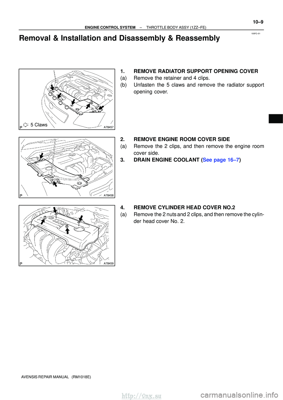
1.REMOVE RADIATOR SUPPORT OPENING COVER
(a)Remove the retainer and 4 clips.
(b)Unfasten the 5 claws and remove the radiator support
opening cover.
2.REMOVE ENGINE ROOM COVER SIDE
(a)Remove the 2 clips, and then remove the engine room cover side.
3.DRAIN ENGINE COOLANT (See page 16±7)
4. REMOVE CYLINDER HEAD COVER NO.2
(a) Remove the 2 nuts and 2 clips, and then remove the cylin- der head cover No. 2.
http://vnx.su
Page 301 of 2234
A78463
A
A
A
A
BB
A
(d)
(c)
A78468
65.1 mm
(2.563 in.)
Rotation
Center of
Throttle Link
18�
10±12
±
ENGINE CONTROL SYSTEMTHROTTLE BODY ASSY(1ZZ±FE)
AVENSIS REPAIR MANUAL (RM1018E)
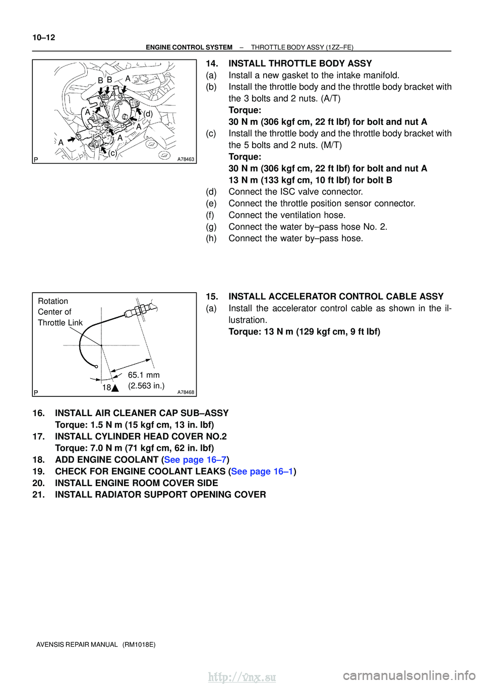
14.INSTALL THROTTLE BODY ASSY
(a)Install a new gasket to the intake manifold.
(b)Install the throttle body and the throttle body bracket with the 3 bolts and 2 nuts. (A/T)
Torque:
30 N�m (306 kgf�cm, 22 ft�lbf) for bolt and nut A
(c)Install the throttle body and the throttle body bracket with
the 5 bolts and 2 nuts. (M/T)
Torque:
30 N�m (306 kgf�cm, 22 ft�lbf) for bolt and nut A
13 N�m (133 kgf�cm, 10 ft�lbf) for bolt B
(d)Connect the ISC valve connector.
(e)Connect the throttle position sensor connector.
(f)Connect the ventilation hose.
(g)Connect the water by±pass hose No. 2.
(h)Connect the water by±pass hose.
15.INSTALL ACCELERATOR CONTROL CABLE ASSY
(a)Install the accelerator control cable as shown in the il-
lustration.
Torque: 13 N�m (129 kgf�cm, 9 ft�lbf)
16.INSTALL AIR CLEANER CAP SUB±ASSY Torque: 1.5 N �m (15 kgf�cm, 13 in. �lbf)
17.INSTALL CYLINDER HEAD COVER NO.2 Torque: 7.0 N �m (71 kgf�cm, 62 in. �lbf)
18.ADD ENGINE COOLANT (See page 16±7)
19.CHECK FOR ENGINE COOLANT LEAKS (See page 16±1)
20. INSTALL ENGINE ROOM COVER SIDE
21. INSTALL RADIATOR SUPPORT OPENING COVER
http://vnx.su
Page 304 of 2234
100FE±01
A78497
A78498
(a)
(b)
(c)
A78499
(d)
(e)
A78500
±
ENGINE CONTROL SYSTEMTHROTTLE BODY ASSY(3ZZ±FE)
10±15
AVENSIS REPAIR MANUAL (RM1018E)
Removal & Installation and Disassembly & Reassembly
1.REMOVE RADIATOR SUPPORT OPENING COVER (See page 10±9)
2.REMOVE ENGINE ROOM COVER SIDE (See page 10±9)
3.DRAIN ENGINE COOLANT (See page 16±7)
4.REMOVE CYLINDER HEAD COVER NO.2 (See page 10±9)
5.REMOVE AIR CLEANER CAP SUB±ASSY (See page 10±9)
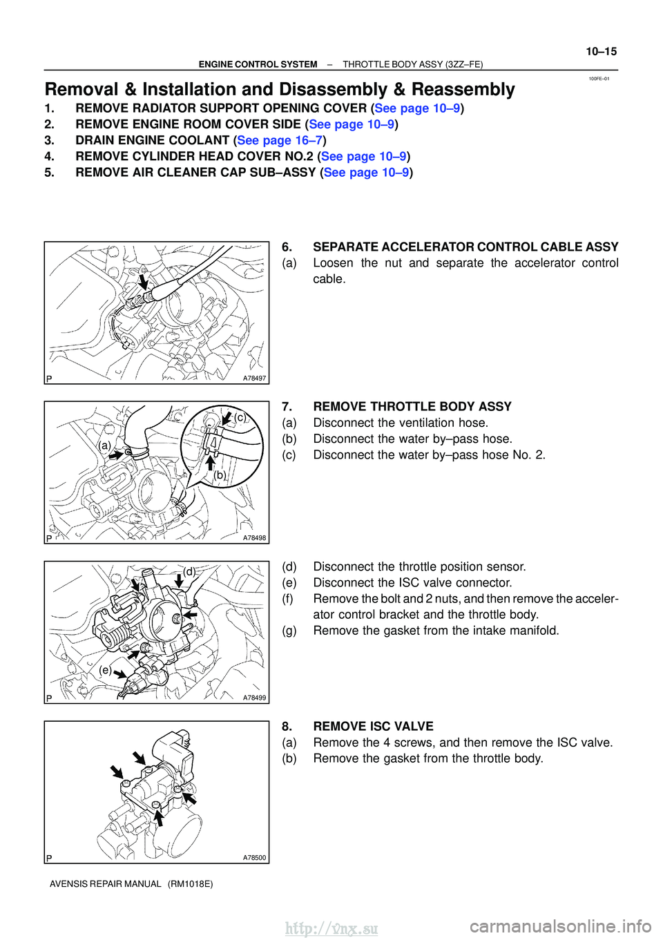
6. SEPARATE ACCELERATOR CONTROL CABLE ASSY
(a) Loosen the nut and separate the accelerator controlcable.
7. REMOVE THROTTLE BODY ASSY
(a) Disconnect the ventilation hose.
(b) Disconnect the water by±pass hose.
(c) Disconnect the water by±pass hose No. 2.
(d) Disconnect the throttle position sensor.
(e) Disconnect the ISC valve connector.
(f) Remove the bolt and 2 nuts, and then remove the acceler- ator control bracket and the throttle body.
(g) Remove the gasket from the intake manifold.
8. REMOVE ISC VALVE
(a) Remove the 4 screws, and then remove the ISC valve.
(b) Remove the gasket from the throttle body.
http://vnx.su