Page 66 of 2234
SFISFISFISFISFISFI
D25842
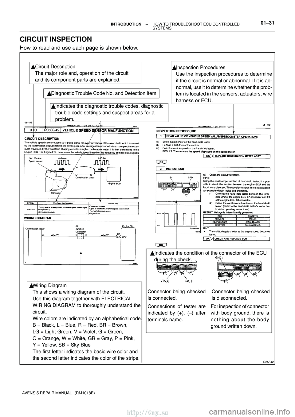
� Circuit Description
The major role and, operation of the circuit
and its component parts are explained.
� Diagnostic Trouble Code No. and Detection Item� Indicates the diagnostic trouble codes, diagnostic
trouble code settings and suspect areas for a
problem.
Wiring Diagram
This shows a wiring diagram of the circuit.
Use this diagram together with ELECTRICAL
WIRING DIAGRAM to thoroughly understand the
circuit.
Wire colors are indicated by an alphabetical code.
B = Black, L = Blue, R = Red, BR = Brown,
LG = Light Green, V = Violet, G = Green,
O = Orange, W = White, GR = Gray, P = Pink,
Y = Yellow, SB = Sky Blue
The first letter indicates the basic wire color and
the second letter indicates the color of the stripe. �Inspection Procedures
Use the inspection procedures to determine
if the circuit is normal or abnormal. If it is ab-
normal, use it to determine whether the prob-
lem is located in the sensors, actuators, wire
harness or ECU.
� Indicates the condition of the connector of the ECU
during the check.
�
Connections of tester are
indicated by (+), (±) after
terminals name.
Connector being checked
is connected.Connector being checked
is disconnected.
For inspection of connector
with body ground, there is
nothing about the body
ground written down.
±
INTRODUCTION HOW TO TROUBLESHOOT ECU CONTROLLED
SYSTEMS01±31
AVENSIS REPAIR MANUAL (RM1018E)
CIRCUIT INSPECTION
How to read and use each page is shown below.
http://vnx.su
Page 75 of 2234
L1L2L1L2L1L2
D02612
L2
L1L2
L1L2
L1
D01201
±
INTRODUCTIONREPAIR INSTRUCTION
01±9
AVENSIS REPAIR MANUAL (RM1018E)
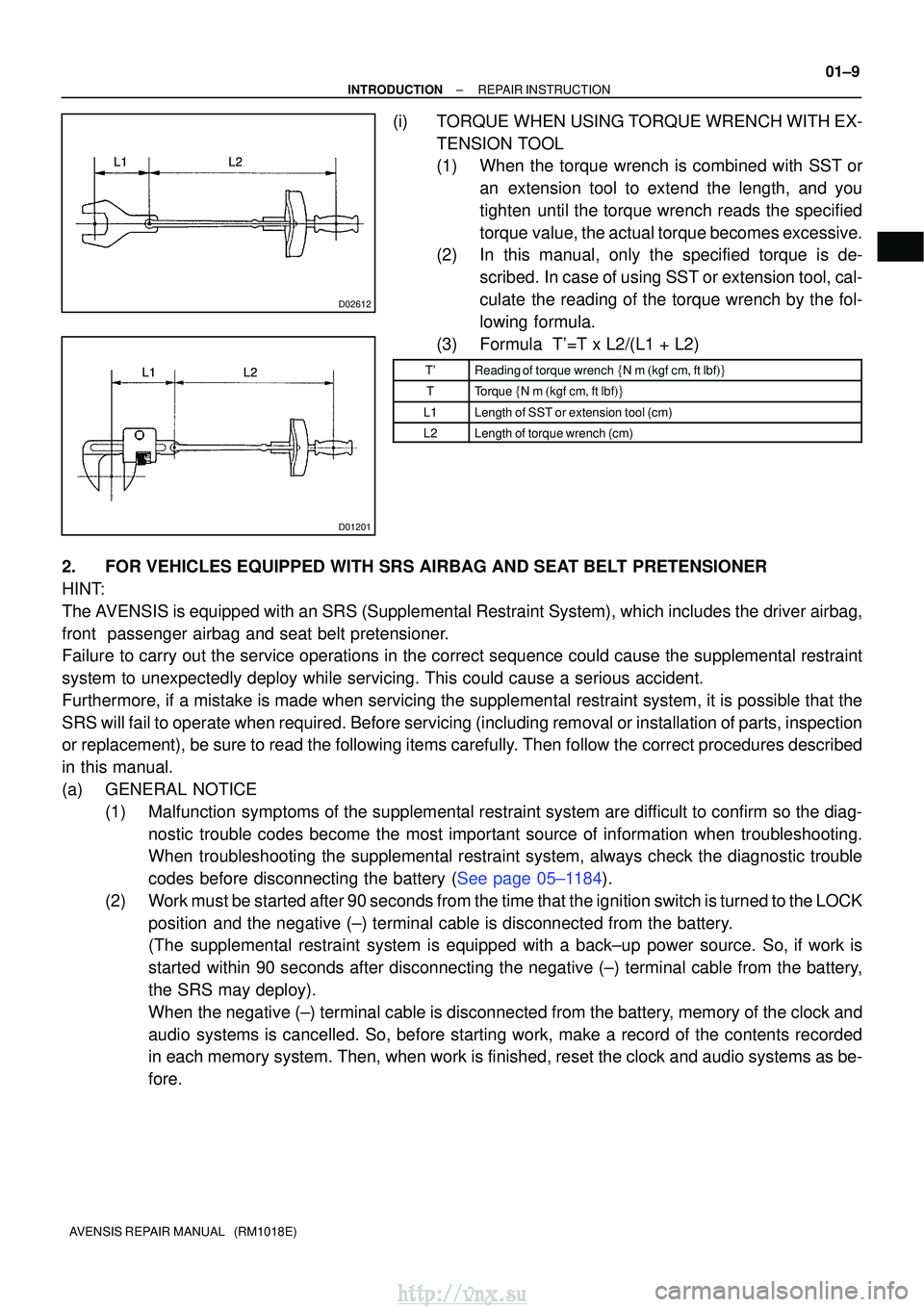
(i)TORQUE WHEN USING TORQUE WRENCH WITH EX-
TENSION TOOL
(1)When the torque wrench is combined with SST oran extension tool to extend the length, and you
tighten until the torque wrench reads the specified
torque value, the actual torque becomes excessive.
(2)In this manual, only the specified torque is de-
scribed. In case of using SST or extension tool, cal-
culate the reading of the torque wrench by the fol-
lowing formula.
(3)Formula T'=T x L2/(L1 + L2)
T'Reading of torque wrench �N�m�kgf�cm�ft�lbf��
TTorque �N�m�kgf�cm�ft�lbf��
L1Length of SST or extension tool (cm)
L2Length of torque wrench (cm)
2.FOR VEHICLES EQUIPPED WITH SRS AIRBAG AND SEAT BELT PRETENSIONER
HINT:
The AVENSIS is equipped with an SRS (Supplemental Restraint System), which \
includes the driver airbag,
front passenger airbag and seat belt pretensioner.
Failure to carry out the service operations in the correct sequence could cause\
the supplemental restraint
system to unexpectedly deploy while servicing. This could cause a seriou\
s accident.
Furthermore, if a mistake is made when servicing the supplemental restra\
int system, it is possible that the
SRS will fail to operate when required. Before servicing (including remova\
l or installation of parts, inspection
or replacement), be sure to read the following items carefully. Then follow the correct procedures described
in this manual.
(a)GENERAL NOTICE (1)Malfunction symptoms of the supplemental restraint system are difficult to confirm so the diag-nostic trouble codes become the most important source of information when trou\
bleshooting.
When troubleshooting the supplemental restraint system, always check the dia\
gnostic trouble
codes before disconnecting the battery (See page 05±1184).
(2) Work must be started after 90 seconds from the time that the ignition switch\
is turned to the LOCK position and the negative (±) terminal cable is disconnected from the batte\
ry.
(The supplemental restraint system is equipped with a back±up power sourc\
e. So, if work is
started within 90 seconds after disconnecting the negative (±) terminal ca\
ble from the battery,
the SRS may deploy).
When the negative (±) terminal cable is disconnected from the battery, memory of the clock and
audio systems is cancelled. So, before starting work, make a record of the contents recorded
in each memory system. Then, when work is finished, reset the clock and audio systems as be-
fore.
http://vnx.su
Page 1731 of 2234
730EY±02
±
THEFT DETERRENT & DOOR LOCK TRANSMITTER SUB±ASSY MODULE SET DOOR
CONTROL73±21
AVENSIS REPAIR MANUAL (RM1018E)
REGISTRATION
1. REGISTER RECOGNITION CODE
HINT:
�Register the recognition code when replacing the door control transmitter or the\
door control receiverr.
�The add mode is used to register new recognition codes while still retai\
ning codes already registered.
This mode is used when a new transmitter is added. If the number of regi\
stered codes exceeds 4, the
previously registered codes will be erased in order, starting from the first registered code.
�The rewrite mode is used to erase all the previously registered recognition\
codes in order to register
new recognition codes. This mode is used when the transmitter or the door control receiver is ex-
changed for a new one.
�The confirmation mode is used to confirm how many recognition codes have al\
ready been registered
before an additional registration of a recognition codes.
�The all clear mode is used to erase all the registered codes and disables t\
he wireless door lock func-
tion. This mode is used when the transmitter is lost.
�All the following registration procedures must be performed in order con\
tinuously.
http://vnx.su