Page 426 of 2234

12±1
AVENSIS REPAIR MANUAL (RM1018E)
EMISSION CONTROL SYSTEM (1ZZ±FE/3ZZ±FE)
ON±VEHICLE INSPE")
1209C±02
A65749
E1OX1AOX1B
ECM
A66059
±
EMISSION CONTROL EMISSION CONTROL SYSTEM (1ZZ±FE/3ZZ±FE)
12±1
AVENSIS REPAIR MANUAL (RM1018E)
EMISSION CONTROL SYSTEM (1ZZ±FE/3ZZ±FE)
ON±VEHICLE INSPECTION
1. INSPECT AIR±FUEL RATIO COMPENSATION SYS-
TEM
HINT:
You can also check the system by choosing ºDATA MONITOR/
O
2 SENSOR OUTPUT VOLTAGEº on the monitor of the hand±
held tester.
(a) Connect the hand±held tester to the terminals 21 (OX1B) and 7 (E1) and to terminals 23 (OX1A) and 7 (E1) of the
ECM.
CAUTION:
Connect test leads from the back side of the connector with
the ECM connected.
(b) Warm up the heated oxygen sensor with the engine speed at 2,500 rpm for approximately 2 minutes.
(c) Confirm that the voltage varies output between 0V to 1V with the engine speed at 2,500 rpm.
OK:
The voltage output varies more than 8 times in 10 se-
conds.
CAUTION:
�Perform the check immediately after the warming up.
�If the voltage variation could not be verified, warm up
the heated oxygen sensor again.
2. INSPECT FUEL CUT OFF RPM
(a) Increase the engine speed to at least 3,500 rpm.
(b) Use a sound scope to check for injector operating sounds.
(c) Check that injector operating sounds stops momentarily and then resumes when \
the throttle lever is released.
3. INSPECT EVAPORATIVE EMISSION CONTROL SYS-TEM
(a) After starting the engine, disconnect the vacuum hose
shown in the illustration.
(b) Check if vacuum occurs at the VSV port when choosing ºACTIVE TESTº and ºPURGE VSVº according to the dis-
play on hand±held tester.
(c) Finish ºACTIVE TESTº, then reconnect the vacuum.
(d) After entering to ºECU DATA MONITORº on the hand±
held tester, choose ºPURGE VSVº to check the operation
of the purge VSV.
(e) After driving the vehicle with a warm engine, confirm that
the VSV turns from off to on.
http://vnx.su
Page 427 of 2234
A62836
1ZZ±FE3ZZ±FE
12±2
±
EMISSION CONTROL EMISSION CONTROL SYSTEM (1ZZ±FE/3ZZ±FE)
AVENSIS REPAIR MANUAL (RM1018E)
4. VISUALLY INSPECT HOSES, CONNECTIONS AND GASKETS
(a) Check for cracks, leaks or damage.
HINT:
Separation of the engine oil dipstick, oil filler cap, PCV hose,
etc. may cause the engine to run improperly. Disconnection,
looseness or cracks in the parts of the air induction system be-
tween the throttle body and cylinder head will allow air suction
and cause the engine to run improperly.
http://vnx.su
Page 428 of 2234
1306S±02
A79032
Filter
AB
A59586
13±2
±
INTAKE INTAKE AIR CONTROL SYSTEM (1AZ±FSE)
AVENSIS REPAIR MANUAL (RM1018E)
INSPECTION
1. INSPECT INTAKE AIR CONTROL VALVE ASSY
(a) With 34.7 kPa (260 mm Hg, 10.2 in. Hg) of vacuum ap- plied to the actuator, check that the actuator rod moves.
(b) One minute after applying the vacuum, check that the ac- tuator rod does not return.
(c) If the operation is not as specified, replace the intake air control valve assembly.
NOTICE:
Do not touch the adjust screw.
2. INSPECT VACUUM SWITCHING VALVE ASSY NO.1
(a) Using an ohmmeter, measure resistance between each terminal.
Resistance: 33 to 39 � at 20 �C (68� F)
(b) Check that air flows form port B to the filter.
(c) Apply battery voltage across the terminals.
(d) Check that air flows from port B to port A.
http://vnx.su
Page 429 of 2234
1302G±03
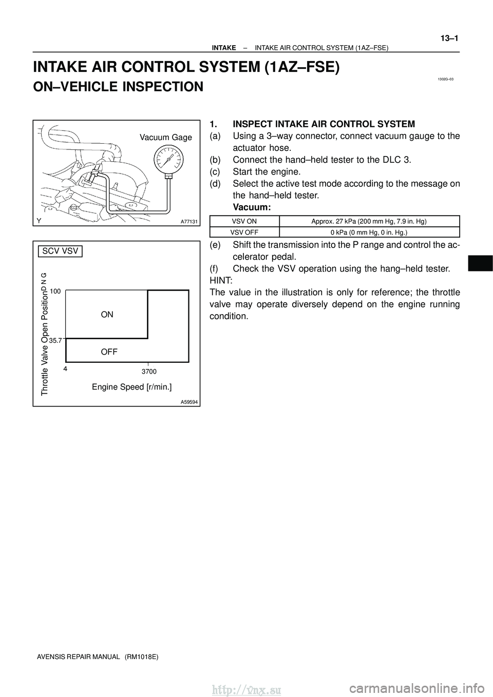
A77131
Vacuum Gage
35.7� 3700
100
Throttle Valve Open Position
���
Engine Speed [r/min.]
ON
OFF
A59594
SCV VSV
±
INTAKE INTAKE AIR CONTROL SYSTEM (1AZ±FSE)
13±1
AVENSIS REPAIR MANUAL (RM1018E)
INTAKE AIR CONTROL SYSTEM (1AZ±FSE)
ON±VEHICLE INSPECTION
1. INSPECT INTAKE AIR CONTROL SYSTEM
(a) Using a 3±way connector, connect vacuum gauge to the
actuator hose.
(b) Connect the hand±held tester to the DLC 3.
(c) Start the engine.
(d) Select the active test mode according to the message on the hand±held tester.
Vacuum:
VSV ONApprox. 27 kPa (200 mm Hg, 7.9 in. Hg)
VSV OFF0 kPa (0 mm Hg, 0 in. Hg.)
(e) Shift the transmission into the P range and control the ac-
celerator pedal.
(f) Check the VSV operation using the hang±held tester.
HINT:
The value in the illustration is only for reference; the throttle
valve may operate diversely depend on the engine running
condition.
http://vnx.su
Page 432 of 2234
13030±02
A60591
A60592
A60593
Air
E G
A60594
Air
Filter Battery
E
±
INTAKE TURBO CHARGER SYSTEM (1CD±FTV)
13±7
AVENSIS REPAIR MANUAL (RM1018E)
INSPECTION
1. VACUUM SWITCHING VALVE ASSY NO.1
(a) Inspect VSV for open circuit.
(1) Using an ohmmeter, check that the there is continu-ity between the terminals.
Resistance: 37 ± 44 � at 20 �C (68� F)
(b) Inspect VSV for ground. (1) Using an ohmmeter, check that there is no continu-ity between each terminal and the body.
Specified condition: No continuity
(c) Inspect VSV operation. (1) Check that air flows from port E to G.
(2) Apply battery voltage across the terminals.
(3) Check that air flows from port E to filter.
http://vnx.su
Page 433 of 2234

13±5
AVENSIS REPAIR MANUAL (RM1018E)
ON±VEHICLE INSPECTION
1. INSPECT INTAKE AIR SYSTEM
(a) Check for leakage or clogging")
1302Z±03
A77123
SST
A60595E2 VC
±
INTAKE TURBO CHARGER SYSTEM (1CD±FTV)
13±5
AVENSIS REPAIR MANUAL (RM1018E)
ON±VEHICLE INSPECTION
1. INSPECT INTAKE AIR SYSTEM
(a) Check for leakage or clogging between the air cleaner
housing and turbocharger inlet and between the turbo-
charger outlet and cylinder head.
(1) Clogged air cleaner...Clean or replace element
(2) Hoses collapsed or deformed...Repair or replace
(3) Leakage from connections...Check each connec-tion and repair
(4) Cracks in components...Check and replace
2. INSPECT EXHAUST SYSTEM
(a) Check for leakage or clogging between the cylinder head
and turbocharger inlet and between the turbocharger out-
let and exhaust pipe.
(1) Deformed components...Repair or replace
(2) Foreign material in passages...Remove
(3) Leakage from components...Repair or replace
(4) Cracks in components...Check and replace
3. CHECK TURBOCHARGING PRESSURE
(a) Warm up the engine.
(b) Using a 3±way connector, connect SST (turbocharger pressure gauge) to the hose leading to the intake air con-
nector.
SST 09992 ± 00242
(c) While depressing the clutch pedal, press the accelerator pedal down to the full. Measure the turbocharging pres-
sure at maximum speed (5,100 to 5,250 rpm).
Standard pressure:
15 to 45 kPa (0.15 to 0.46 kgf/cm
2, 2.2 to 6.5 psi)
If the pressure is less than specification, check both the intake
air and exhaust systems for leakage.
If there is no leakage, check if the actuator hose has discon-
nected. If not, check the turbocharger.
If the pressure is greater than specification, check if the actua-
tor hose has disconnected or cracked. If not, check the turbo-
charger.
4. INSPECT TURBO PRESSURE SENSOR
(a) Inspect power source voltage (1) Disconnect the turbo pressure sensor connector.
(2) Turn the ignition switch ON.
(3) Using a voltmeter, measure the voltage between
connector terminals 3 (VC) and 1 (E2) of the wiring
harness side.
Voltage: 4.5 to 5.5 V
(4) Turn the ignition switch OFF.
(5) Reconnect the turbo pressure sensor connector.
http://vnx.su
Page 435 of 2234

13±3
AVENSIS REPAIR MANUAL (RM1018E)
TURBO CHARGER SYSTEM (1CD±FTV)
PRECAUTION
1. MAINTENANCE PRECAUTION
(a) Do not stop th")
1302Y±03
A77119
A77120
A77121
±
INTAKE TURBO CHARGER SYSTEM (1CD±FTV)
13±3
AVENSIS REPAIR MANUAL (RM1018E)
TURBO CHARGER SYSTEM (1CD±FTV)
PRECAUTION
1. MAINTENANCE PRECAUTION
(a) Do not stop the engine immediately after pulling a trailer,
or after driving at a high speed, or uphill drive. Let the en-
gine Idle for 20 to 120 seconds before turn the ignition
switch OFF (According as the driving condition, the idling
time varies).
(b) Avoid quick acceleration or quickly accelerating the en- gine RPM immediately after the starting a cold engine.
(c) If the turbocharger is found to be defective, it must be re-
placed. Also, inspect a source of the trouble including
conditions of the turbocharger that having been used. Re-
pair or replace the followings as necessary:
(1) Engine oil (Level and quality)
(2) Oil lines leading to the turbocharger
(d) Pay due attention when removing and reinstalling the turbocharger assembly. Do not drop, or do not give shock,
or do not grasp easily±deformed assembly parts such as
the actuator or push rod in removal and reinstallation.
(e) Before removal, cover both the intake and exhaust ports
and the oil inlet to prevent dirt or foreign objects from be-
ing introduced.
(f) If replacing the turbocharger, check for deposits in the oil pipe. If necessary, replace the oil pipe too.
(g) Thoroughly remove old gasket sticking to the lubrication oil pipe flange and the turbocharger oil flange.
(h) If replacing the bolt(s) or nut(s), must use Toyota genuine parts to prevent breakage or deformation.
(i) If replacing the turbocharger, put 20 cm
3 (1.2 cu in.) of
fresh oil into the turbocharger oil inlet hole and turn the tur-
bine wheel by hand to spread oil to the bearing.
(j) If overhauling or replacing the engine, cut the fuel supply after reassembly and crank the engine for 30 seconds to
feed oil throughout the engine then run the engine at idle
for 60 seconds.
http://vnx.su
Page 446 of 2234
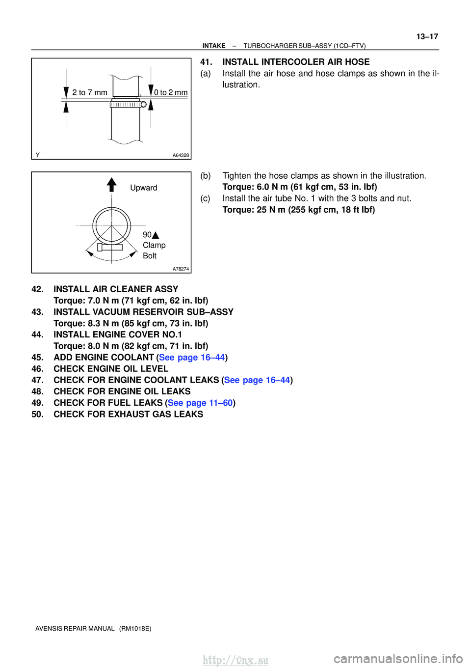
A64328
2 to 7 mm0 to 2 mm
A78274
Upward90�
Clamp
Bolt
±
INTAKETURBOCHARGER SUB±ASSY(1CD±FTV)
13±17
AVENSIS REPAIR MANUAL (RM1018E)
41.INSTALL INTERCOOLER AIR HOSE
(a)Install the air hose and hose clamps as shown in the il-
lustration.
(b)Tighten the hose clamps as shown in the illustration. Torque: 6.0 N �m (61 kgf�cm, 53 in. �lbf)
(c)Install the air tube No. 1 with the 3 bolts and nut. Torque: 25 N �m (255 kgf�cm, 18 ft�lbf)
42.INSTALL AIR CLEANER ASSY Torque: 7.0 N �m (71 kgf�cm, 62 in. �lbf)
43.INSTALL VACUUM RESERVOIR SUB±ASSY Torque: 8.3 N �m (85 kgf�cm, 73 in. �lbf)
44.INSTALL ENGINE COVER NO.1
Torque: 8.0 N �m (82 kgf�cm, 71 in. �lbf)
45.ADD ENGINE COOLANT(See page 16±44)
46. CHECK ENGINE OIL LEVEL
47.CHECK FOR ENGINE COOLANT LEAKS(See page 16±44)
48. CHECK FOR ENGINE OIL LEAKS
49.CHECK FOR FUEL LEAKS(See page 11±60)
50. CHECK FOR EXHAUST GAS LEAKS
http://vnx.su

AVENSIS REPAIR MANUAL (RM1018E)
4. VISUALLY INSPECT HOSES, CONNECTIONS AND GASKETS
(a) Check for cracks, lea")

AVENSIS REPAIR MANUAL (RM1018E)
INSPECTION
1. INSPECT INTAKE AIR CONTROL VALVE ASSY
(a) With 34.7 kPa (260 mm H")

13±7
AVENSIS REPAIR MANUAL (RM1018E)
INSPECTION
1. VACUUM SWITCHING VALVE ASSY NO.1
(a)")