2003 SSANGYONG MUSSO EGR
[x] Cancel search: EGRPage 926 of 1574

AUTOMATIC TRANSMISSION 5A-67
Table 6.1.3 - Diagnostic Trouble Messages
Description / Cause
There have been no faults recorded since the TCU was last cleared. If
the fault history has never been cleared, then there have been no
faults recorded since the TCU was originally powered up.There is an internal fault within the TCU.
The voltage measured by the TCU corresponding to the battery sup-
ply voltage has been outside the range of the maximum operatingvoltage of 16.5 volts.
The minimum operating voltage depends on the transmission tem-
perature but is typically between 8-9 V for a warm transmission.
The voltage measured by the TCU from the throttle potentiometer has been outside acceptable levels.
This would typically indicate a loose connection in the wiring to, or
within, the throttle sensor which has caused the signal at the TCU to
read 0V or 5V.
The voltage measured by the TCU across the temperature Input ter-
minals has been outside acceptable levels.
This would typically be caused by a loose connection or short to ground
in the wiring to, or within, the temperature sensor which has caused
the signal at the TCU to read 0V or 5V. The voltage measured by the TCU across the shift lever input termi- nals has been outside acceptable levels for a significant length of
time. This would typically be caused by a loose connection or short to
ground in the wiring to, or within, the inhibitor switch which has caused
the signal at the TCU to read 0V or 5V.
The signal from the ignition, of ignition pulses, has either been non- existent or has been unreliable.
There are two reasons this fault could occur. The first is due to a lack
of ignition pulses when other TCU inputs would indicate that the en-
gine is running, that is the gear lever is in a driving position, the throttle is applied and vehicle speed increasing. The second cause of this (aunt is the frequency of the pulses of theignition pulse input to the TCU indicate an unachievable engine speed.
The pulses from the shaft speed sensor have either been non-exis-tent or have been unreliable.
There are three reasons this fault could occur. The first is due to a sudden loss of speedometer pulses at a time when they were fre quent,thus indicating an unachievable degree of deceleration of the drive
line. The second cause of this fault is that the frequency of the pulses
on the shaft speed sensor input to the TCU indicate an unachievable
propeller shaft speed. The third is the presence of a high engine speed
in a driving gear with no speedometer pulses.
Condition
Test Pass
Transmission Control Module Fault
Battery Voltage InputFault Throttle Input Fault
Temperature Input FaultShift Lever Position Input Fault(Inhibitor/PRNDL Switch) Engine Speed Sensor Fault Shaft Speed Sensor Fault(Speedo Sensor)Solenoid 1 2 3 4567 8
Page 938 of 1574

AUTOMATIC TRANSMISSION 5A-79
ADJUSTMENTS
HYDRAULIC SYSTEM
The procedures detailed below should be followed in the event that the self test procedure detailed in section 6, or a
defect symptom, indicates that there is a fault in the hydraulic system.
When making adjustments to the transmission, select the appropriate procedures from the following preliminary checks. � Conduct a transmission fluid test procedure, refer to section 7.2.
� Check the manual linkage adjustment (refer to the vehicle workshop manual).
� Check engine idle speed (refer to Section 7.3).
� Conduct a stall test (it is outside the scope of this publication to detail this procedure)
� conduct a road test (it is outside the scope of this publication to detail this procedure).
TRANSMISSION FLUID TEST PROCEDURE
Checking Transmission Fluid Level
This procedure is to be used when checking a concern with the fluid level in a vehicle. A low fluid level will result in
gearshift loss or delay if driven when the vehicle is cold.
The vehicle is first checked for transmission diagnostic messages (refer to section 6). If the vehicle has a speedo fault
it is possible for the oil level to be low.
The vehicle is to be test driven to determine if there is an abnormal delay when selecting drive or reverse, or loss of
drive. One symptom of low oil level is a momentary loss of drive when driving the vehicle around a comer. Also when
the transmission fluid level is low, a loss of drive may occur when the transmission oil temperature is low.
If there is no loss of drive when the vehicle is driven warm and a speedo fault is registered, then fluid should be addedto the transmission.
Checking, Adding Fluid and Filling
When adding or changing transmission oil use only Castrol TQ 95 automatic transmission fluid (A TF) or other approved
fluids. The use of incorrect oil will cause the performance and durability of the transmission to be severely degraded. Do not underfill the transmission. Incorrect tilling may cause damage to the transmission. The fluid level setting
procedure is detailed below. Notice
When a transmission is at operating temperature hot transmission fluid may come out of the case if the fill plug is
removed. 9 the transmission is at operating temperature allow two hours for cooling prior to removing the plug.
1. If the vehicle is at operating temperature allow the vehicle to cool down for two, but no greater than four hours before adding transmission fluid (this will allow the transmission to be within the correct temperaturerange).
While hot the ATF level is higher and removing the plug may result in oil being expelled from the filler hole. This
will result in the level being low.
2. The transmission selector is to be in Park. Switch the engine off.
3. Raise the vehicle on a hoist (or leave over a service pit).
4. Clean all dirt from around the service fill plug prior to removing the plug. Remove the oil service fill plug. Clean the fill plug and check that there is no damage to the ‘O’ ring.
Install the filler pump into the filler hole.
5. Lower the vehicle with the filler pump still connected and partially fill the transmission.
Start the vehicle in Park with the Parking brake and foot brake applied with the engine idling, cycle the transmission
gear selector through all positions, adding ATF until gear application is felt.
Page 940 of 1574

AUTOMATIC TRANSMISSION 5A-81
Throttle Clearing
The leant throttle clearing routine uses the mode switch and gear lever. Carry out the following steps to complete the
automated throttle clearing procedure:
1. Switch ignition ‘ON ’ with handbrake applied and engine ‘OFF ’.
2. Select ‘M1 ’ and ‘WINTER ’ mode.
3. Move the T-bar to ‘M2 ’ and then select ‘NORMAL ’ or ‘POWER ’ mode.
4. Move the T-bar to ‘M3 ’ and then select ‘WINTER ’ mode.
Vehicle Coding
The vehicle coding is integrated as part of the diagnostic software. The coding applies to the following vehicle models: 1. 4WD Gasoline E32.
2. 4WD Gasoline 523
3. 4WD Gasoline 520.
4. 4WD Diesel D29NA.
5. 4WD Diesel D29LA.
6. 4WD Diesel D23LA.
7. RWD E20.
8. RWD E23.
Page 1212 of 1574
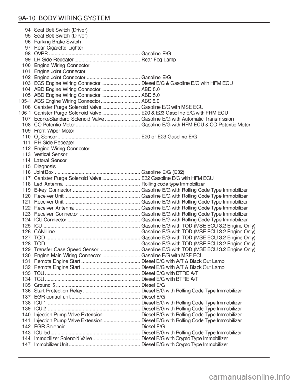
9A-10 BODY WIRING SYSTEM94 Seat Belt Switch (Driver)
95 Seat Belt Switch (Dirver)
96 Parking Brake Switch
97 Rear Cigarette Lighter
9 8 OVPR ................................................................. Gasoline E/G
99 LH Side Repeater ............................................... Rear Fog Lamp
100 Engine Wiring Connector
101 Engine Joint Connector
102 Engine Joint Connector ......................................Gasoline E/G
103 ECS Engine Wiring Connector ...........................Diesel E/G & Gasoline E/G with HFM ECU
104 ABD Engine Wiring Connector ...........................ABD 5.0
105 ABD Engine Wiring Connector ...........................ABD 5.0
105-1 ABS Engine Wiring Connector ............................ABS 5.0
106 Canister Purge Solenoid Valve ...........................Gasoline E/G with MSE ECU
106-1 Canister Purge Solenoid Valve ...........................E20 & E23 Gasoline E/G with FHM ECU
107 Econo/Standard Solenoid Valve .........................Gasoline E/G with Automatic Transmission
108 CO Potentio Meter .............................................. Gasoline E/G with HFM ECU & CO Potentio Meter
109 Front Wiper Motor 11 0 O 2 Sensor
........................................................... E20 or E23 Gasoline E/G
111 RH Side Repeater
112 Engine Wiring Connector
113 Vertical Sensor
114 Lateral Sensor
115 Diagnosis
11 6 Joint Box ............................................................. Gasoline E/G (E32)
117 Canister Purge Solenoid Valve ...........................E32 Gasoline E/G with HFM ECU
118 Led Antenna ...................................................... Rolling code type Immobilizer
119 E-key Connector ................................................ Gasoline E/G with Rolling Code Type Immobilizer
120 Receiver Unit ...................................................... Gasoline E/G with Rolling Code Type Immobilizer
121 Receiver Unit ...................................................... Gasoline E/G with Rolling Code Type Immobilizer
122 Receiver Antenna .............................................. Gasoline E/G with Rolling Code Type Immobilizer
123 Receiver Connector ........................................... Gasoline E/G with Rolling Code Type Immobilizer
124 ICU Connector .................................................... Gasoline E/G with Rolling Code Type Immobilizer
125 ICU ..................................................................... Gasoline E/G with TOD (MSE ECU 3.2 Engine Only)
126 CAN Line ............................................................ Gasoline E/G with TOD (MSE ECU 3.2 Engine Only)
127 TOD ................................................................... Gasoline E/G with TOD (MSE ECU 3.2 Engine Only)
128 TOD ................................................................... Gasoline E/G with TOD (MSE ECU 3.2 Engine Only)
129 Transfer Case Speed Sensor .............................Gasoline E/G with TOD (MSE ECU 3.2 Engine Only)
130 Engine Main Wiring Connector ...........................Gasoline E/G with MSE ECU
131 Remote Engine Start .......................................... Diesel E/G with A/T & Black Out Lamp
132 Remote Engine Start .......................................... Diesel E/G with A/T & Black Out Lamp
133 TCU .................................................................... Diesel E/G with BTRE A/T
134 TCU .................................................................... Diesel E/G with BTRE A/T
135 Ground 5 ............................................................ Diesel E/G
136 Start Protection Relay .........................................Diesel E/G with Rolling Code Type Immobilizer
137 EGR control unit ................................................. Diesel E/G
1 3 8 ICU 1 .................................................................. Diesel E/G with Rolling Code Type Immobilizer
1 3 9 ICU 2 .................................................................. Diesel E/G with Rolling Code Type Immobilizer
140 Injection Pump Valve Extension ..........................Diesel E/G with Rolling Code Type Immobilizer
141 Injection Pump Valve Extension ..........................Diesel E/G with Rolling Code Type Immobilizer
142 EGR Solenoid .................................................... Diesel E/G
143 ICU led ................................................................ Diesel E/G with Rolling Code Type Immobilizer
144 Immobilizer Solenoid Valve ..................................Diesel E/G with Crypto Type Immobilizer
147 Immobilizer Unit ................................................... Diesel E/G with Crypto Type Immobilizer
Page 1238 of 1574
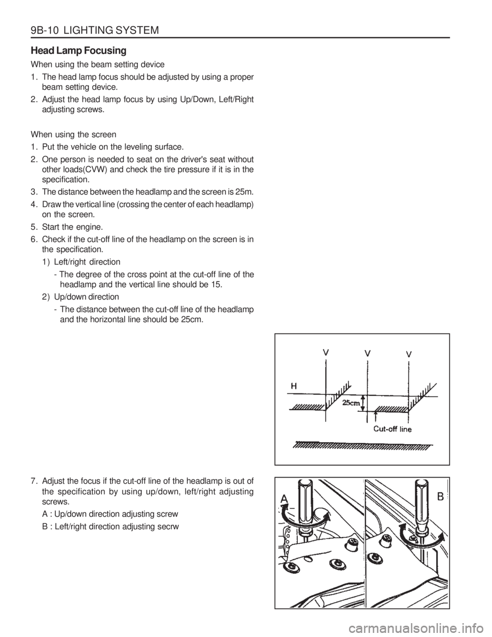
9B-10 LIGHTING SYSTEM Head Lamp Focusing When using the beam setting device
1. The head lamp focus should be adjusted by using a properbeam setting device.
2. Adjust the head lamp focus by using Up/Down, Left/Right adjusting screws.
When using the screen
1. Put the vehicle on the leveling surface.
2. One person is needed to seat on the driver's seat without other loads(CVW) and check the tire pressure if it is in the specification.
3. The distance between the headlamp and the screen is 25m.
4. Draw the vertical line (crossing the center of each headlamp) on the screen.
5. Start the engine.
6. Check if the cut-off line of the headlamp on the screen is in the specification.
1 ) Left/right direction
- The degree of the cross point at the cut-off line of theheadlamp and the vertical line should be 15.
2 ) Up/down direction - The distance between the cut-off line of the headlampand the horizontal line should be 25cm.
7. Adjust the focus if the cut-off line of the headlamp is out of
the specification by using up/down, left/right adjusting screws. A : Up/down direction adjusting screwB : Left/right direction adjusting secrw
Page 1315 of 1574
MUSSO-SPORTS 1A-3
SUPPLEMENT
HUBER EGR
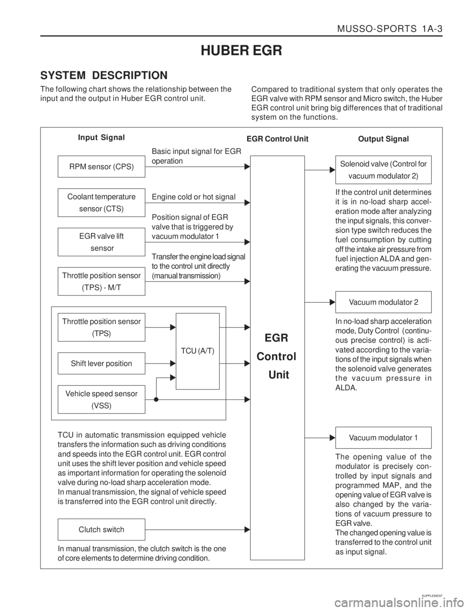
SYSTEM DESCRIPTION The following chart shows the relationship between the input and the output in Huber EGR control unit. Compared to traditional system that only operates theEGR valve with RPM sensor and Micro switch, the HuberEGR control unit bring big differences that of traditionalsystem on the functions.
Input Signal
RPM sensor (CPS)
EGR valve lift sensor
Throttle position sensor (TPS) - M/T
Shift lever position
Throttle position sensor (TPS)
Vehicle speed sensor(VSS) Basic input signal for EGR operation Engine cold or hot signal
Position signal of EGR valve that is triggered by vacuum modulator 1 Transfer the engine load signal to the control unit directly (manual transmission)
TCU (A/T)
EGR
Control
Unit
Coolant temperature sensor (CTS)
Solenoid valve (Control forvacuum modulator 2)
If the control unit determines it is in no-load sharp accel- eration mode after analyzing the input signals, this conver- sion type switch reduces the fuel consumption by cutting off the intake air pressure from
fuel injection ALDA and gen- erating the vacuum pressure. In no-load sharp acceleration
mode, Duty Control ( continu- ous precise control) is acti- vated according to the varia- tions of the input signals when the solenoid valve generates the vacuum pressure in ALDA.
Vacuum modulator 2
The opening value of the modulator is precisely con- trolled by input signals and programmed MAP, and the opening value of EGR valve is also changed by the varia- tions of vacuum pressure to EGR valve. The changed opening value is transferred to the control unit as input signal.
Vacuum modulator 1
TCU in automatic transmission equipped vehicle transfers the information such as driving conditions and speeds into the EGR control unit. EGR control unit uses the shift lever position and vehicle speed as important information for operating the solenoid valve during no-load sharp acceleration mode. In manual transmission, the signal of vehicle speed is transferred into the EGR control unit directly.
Clutch switch
In manual transmission, the clutch switch is the one of core elements to determine driving condition. Output Signal
EGR Control Unit
Page 1316 of 1574
1A-4 MUSSO-SPORTS
SUPPLEMENT
from vacuum pump
EGR valve
EGR control unit
KAA5A020
KAA5A020
KAA5A020
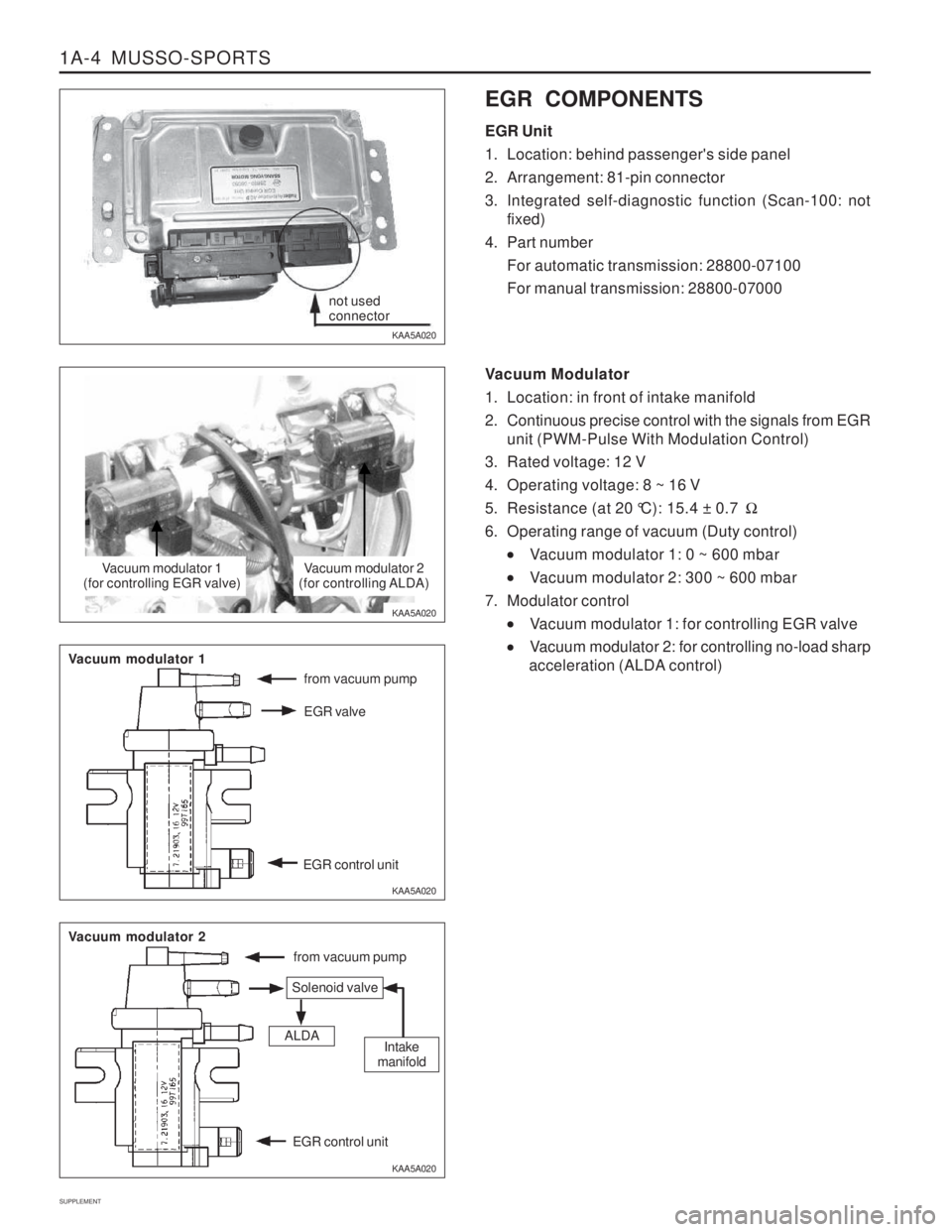
KAA5A020 EGR COMPONENTS EGR Unit
1. Location: behind passenger's side panel
2. Arrangement: 81-pin connector
3. Integrated self-diagnostic function (Scan-100: not
fixed)
4. Part number For automatic transmission: 28800-07100 For manual transmission: 28800-07000
Vacuum Modulator
1. Location: in front of intake manifold
2. Continuous precise control with the signals from EGR unit (PWM-Pulse With Modulation Control)
3. Rated voltage: 12 V
4. Operating voltage: 8 ~ 16 V
5. Resistance (at 20 °C): 15.4 ± 0.7 �
6. Operating range of vacuum (Duty control)
Vacuum modulator 1: 0 ~ 600 mbar
Vacuum modulator 2: 300 ~ 600 mbar
7. Modulator control
Vacuum modulator 1: for controlling EGR valve
Vacuum modulator 2: for controlling no-load sharp
acceleration (ALDA control)
not used connector
Vacuum modulator 1
(for controlling EGR valve)Vacuum modulator 2
(for controlling ALDA)
from vacuum pump
Vacuum modulator 1
Vacuum modulator 2
Solenoid valve
ALDAIntake
manifold
EGR control unit
Page 1317 of 1574
MUSSO-SPORTS 1A-5
SUPPLEMENT
KAA5A020
KAA5A020
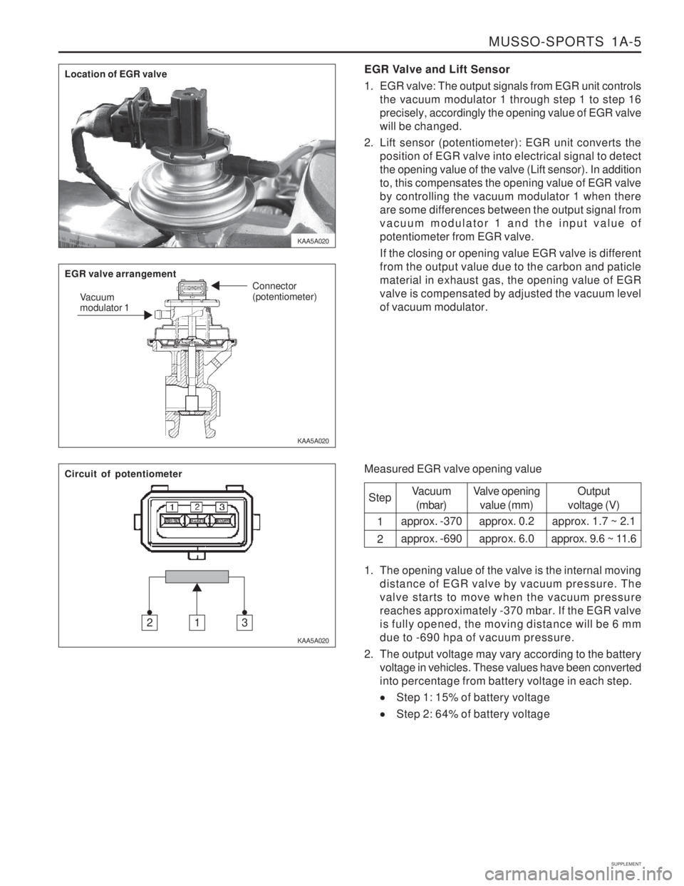
KAA5A020EGR Valve and Lift Sensor
1. EGR valve: The output signals from EGR unit controls
the vacuum modulator 1 through step 1 to step 16 precisely, accordingly the opening value of EGR valvewill be changed.
2. Lift sensor (potentiometer): EGR unit converts the position of EGR valve into electrical signal to detectthe opening value of the valve (Lift sensor). In additionto, this compensates the opening value of EGR valveby controlling the vacuum modulator 1 when thereare some differences between the output signal fromvacuum modulator 1 and the input value ofpotentiometer from EGR valve. If the closing or opening value EGR valve is different from the output value due to the carbon and paticlematerial in exhaust gas, the opening value of EGRvalve is compensated by adjusted the vacuum levelof vacuum modulator.
Measured EGR valve opening value Step 1 2
Vacuum(mbar)
approx. -370 approx. -690 Valve opening
value (mm)
approx. 0.2approx. 6.0 Output
voltage (V)
approx. 1.7 ~ 2.1
approx. 9.6 ~ 11.6
1. The opening value of the valve is the internal moving distance of EGR valve by vacuum pressure. The valve starts to move when the vacuum pressurereaches approximately -370 mbar. If the EGR valveis fully opened, the moving distance will be 6 mmdue to -690 hpa of vacuum pressure.
2. The output voltage may vary according to the battery voltage in vehicles. These values have been convertedinto percentage from battery voltage in each step.
Step 1: 15% of battery voltage
Step 2: 64% of battery voltage
Location of EGR valve EGR valve arrangement
Vacuum modulator 1 Connector (potentiometer)
Circuit of potentiometer
312