Page 1318 of 1574

1A-6 MUSSO-SPORTS
SUPPLEMENT
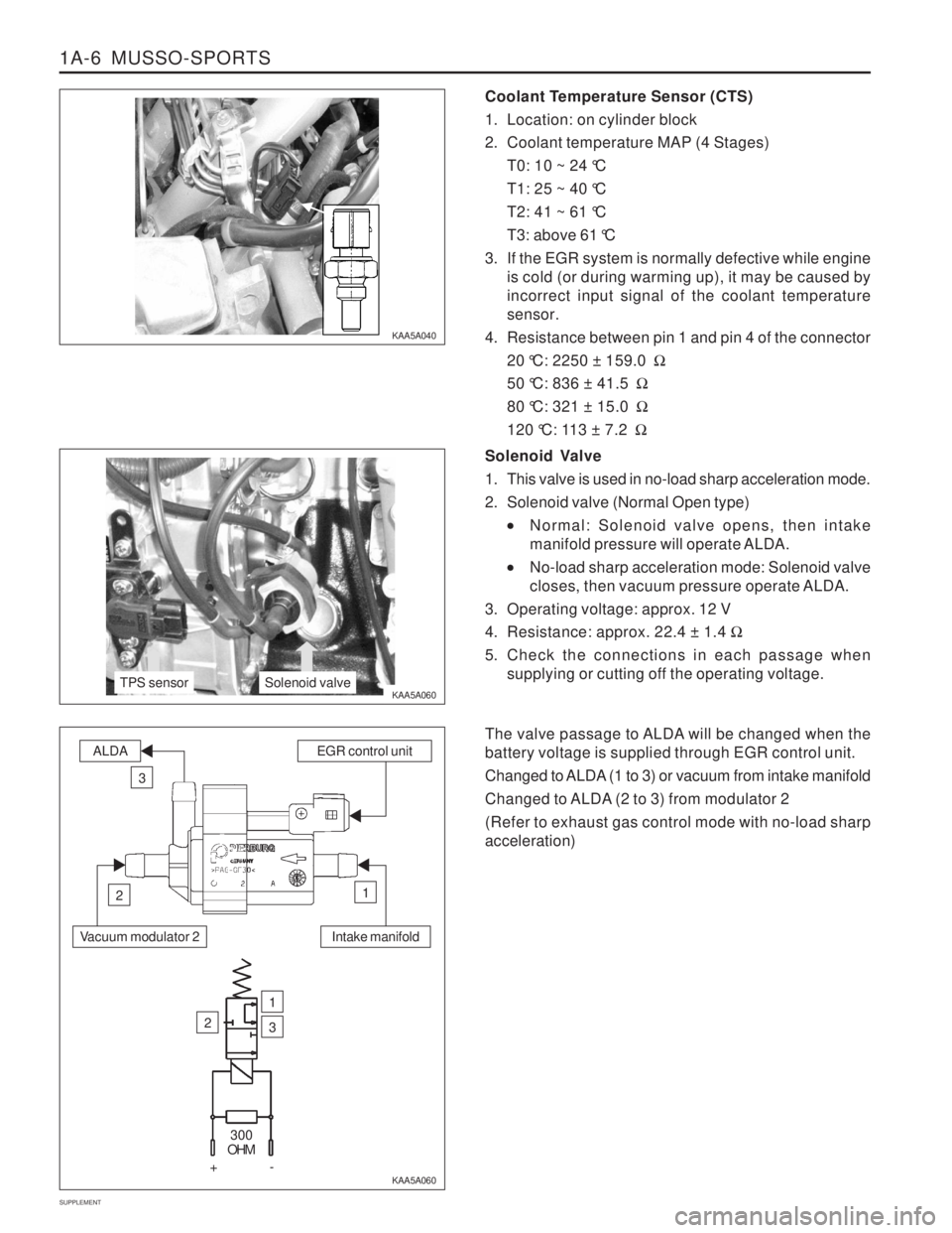
Coolant Temperature Sensor (CTS)
1. Location: on cylinder block
2. Coolant temperature MAP (4 Stages) T0: 10 ~ 24 °C
T1: 25 ~ 40 °C
T2: 41 ~ 61 °C
T3: above 61 °C
3. If the EGR system is normally defective while engine is cold (or during warming up), it may be caused by incorrect input signal of the coolant temperaturesensor.
4. Resistance between pin 1 and pin 4 of the connector 20 °C: 2250 ± 159.0 �
50 °C: 836 ± 41.5 �
80 °C: 321 ± 15.0 �
120 °C: 113 ± 7.2 �
KAA5A040 KAA5A060
KAA5A060Solenoid Valve
1. This valve is used in no-load sharp acceleration mode.
2. Solenoid valve (Normal Open type)
Normal: Solenoid valve opens, then intake
manifold pressure will operate ALDA.
No-load sharp acceleration mode: Solenoid valve
closes, then vacuum pressure operate ALDA.
3. Operating voltage: approx. 12 V
4. Resistance: approx. 22.4 ± 1.4 �
5. Check the connections in each passage when supplying or cutting off the operating voltage.
The valve passage to ALDA will be changed when the battery voltage is supplied through EGR control unit.
Changed to ALDA (1 to 3) or vacuum from intake manifold
Changed to ALDA (2 to 3) from modulator 2 (Refer to exhaust gas control mode with no-load sharp acceleration)
TPS sensorSolenoid valve
Intake manifold
ALDAEGR control unit
3
12
Vacuum modulator 2
2
1
3
300
OHM
+-
Page 1319 of 1574
MUSSO-SPORTS 1A-7
SUPPLEMENT
Throttle Position Sensor (TPS)
1. EGR unit receives TPS signal from TCU (A/T) or input
signal from pin 61 of EGR unit (M/T). The load value of engine is important signal because Huber EGRsystem make EGR valve operate in extended rangeexcept no-load sharp acceleration mode.
2. Resistance check
Disconnect the TPS sensor connector from fuelinjection pump and measure the entire resistancebetween pin 1 and pin 4. Specified value: 5 k � ± 20 %
Measure the resistance between pin 1 and pin 2 at no-load and full-load. Approx. 10 ~ 20 % of full resistance at no-load Approx. 70 ~ 85 % of full resistance at full-load
3. Voltage check
The supplied voltage to TPS from EGR unit (for
M/T) or TCU (for A/T) is approx. 5 V. 0.60 ± 0.2 V at no-load 3.85 ± 0.3 V at full-load
VACUUM LINE Installation of modulator and vacuum line (on-vehicle)
E GR n
Page 1320 of 1574
1A-8 MUSSO-SPORTS
SUPPLEMENT MAINTENANCE AND REPAIR
VACUUM PUMP AND VACUUM LINE This diagnosis procedure checks for vacuum leaks and actuator's operation while performing the actual control of EGR unit through vacuum lines in vacuum pump. The following special service tools should be used for this procedure.
001 589 73 21 00
Manual Vacuum Pump
Multi-Tester 201 589 13 21 00
Vacuum Tester
KAA5A2P0
KAA5A2R0 KAA5A2Q0
VACUUM LINE TEST Check the EGR system when the vehicle produces excessive exhaust gas. Check the vacuum lines for leaks and blocks. If there are not any faults, check the actuators controlled by EGR control unit. Install the tester in position according to the vacuum circuit diagram.
To prevent personal injury, beware of moving parts of engine.
Page 1321 of 1574

MUSSO-SPORTS 1A-9
SUPPLEMENT
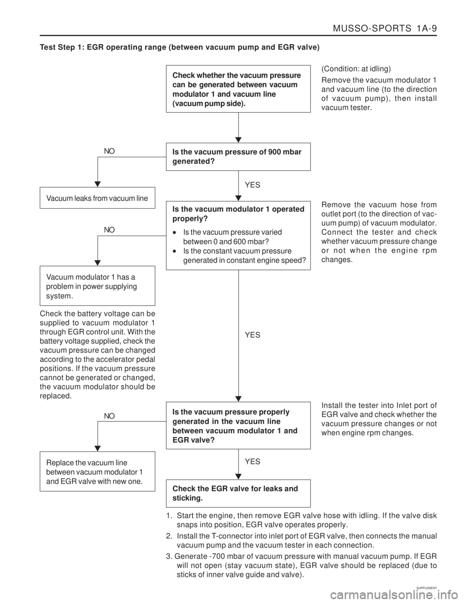
Test Step 1: EGR operating range (between vacuum pump and EGR valve)
(Condition: at idling) Remove the vacuum modulator 1 and vacuum line (to the directionof vacuum pump), then installvacuum tester.
Check whether the vacuum pressure can be generated between vacuum modulator 1 and vacuum line (vacuum pump side).
Is the vacuum pressure of 900 mbar generated?
Is the vacuum pressure properly generated in the vacuum line between vacuum modulator 1 and EGR valve?
Check the EGR valve for leaks and sticking.
Remove the vacuum hose from outlet port (to the direction of vac-uum pump) of vacuum modulator.Connect the tester and checkwhether vacuum pressure changeor not when the engine rpmchanges. Install the tester into Inlet port of EGR valve and check whether thevacuum pressure changes or notwhen engine rpm changes.
1. Start the engine, then remove EGR valve hose with idling. If the valve disk snaps into position, EGR valve operates properly.
2. Install the T-connector into inlet port of EGR valve, then connects the manual vacuum pump and the vacuum tester in each connection.
3. Generate -700 mbar of vacuum pressure with manual vacuum pump. If EGR will not open (stay vacuum state), EGR valve should be replaced (due tosticks of inner valve guide and valve).Vacuum leaks from vacuum line
NO
Is the vacuum modulator 1 operated properly?
Is the vacuum pressure varied
between 0 and 600 mbar?
Is the constant vacuum pressure
generated in constant engine speed?
Check the battery voltage can be supplied to vacuum modulator 1through EGR control unit. With thebattery voltage supplied, check thevacuum pressure can be changedaccording to the accelerator pedalpositions. If the vacuum pressurecannot be generated or changed,the vacuum modulator should bereplaced.
NO
Vacuum modulator 1 has a problem in power supplying system.
NO
Replace the vacuum line between vacuum modulator 1 and EGR valve with new one.
YES YES
YES
Page 1322 of 1574

1A-10 MUSSO-SPORTS
SUPPLEMENT
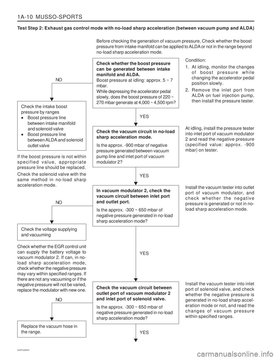
Test Step 2: Exhaust gas control mode with no-load sharp acceleration (between vacuum pump and ALDA)
Condition:
1. At idling, monitor the changesof boost pressure while changing the accelerator pedalposition slowly.
2. Remove the inlet port from ALDA on fuel injection pump,then install the pressure tester.
Before checking the generation of vacuum pressure, Check whether the boost
pressure from intake manifold can be applied to ALDA or not in the range beyond no-load sharp acceleration mode. Check whether the boost pressure can be generated between intake manifold and ALDA. Boost pressure at idling: approx. 5 ~ 7 mbar. While depressing the accelerator pedal slowly, does the boost pressure of 220 ~ 270 mbar generate at 4,000 ~ 4,500 rpm?
At idling, install the pressure tester into inlet port of vacuum modulator2 and read the negative pressure(specified value: approx. -900mbar) on tester. Install the vacuum tester into inlet port of solenoid valve, and checkwhether the negative pressure isgenerated in no-load sharp accel-eration mode or not, and read thechanges of vacuum pressurewithin specified ranges.
NO
If the boost pressure is not within specified value, appropriatepressure line should be replaced. Check the solenoid valve with the same method in no-load sharpacceleration mode.
YES
YES
Check the vacuum circuit in no-load sharp acceleration mode. Is the approx. -900 mbar of negative pressure generated between vacuum pump line and inlet port of vacuum modulator 2?
In vacuum modulator 2, check the vacuum circuit between inlet port and outlet port. Is the approx. -300 ~ 650 mbar of negative pressure generated in no-load sharp acceleration mode?
Check the vacuum circuit between outlet port of vacuum modulator 2 and inlet port of solenoid valve. Is the approx. -300 ~ 650 mbar of negative pressure generated in no-load sharp acceleration mode?
Install the vacuum tester into outlet port of vacuum modulator, andcheck whether the negativepressure is generated or not in no-load sharp acceleration mode.
Check the intake boost pressure by ranges
Boost pressure line
between intake manifold and solenoid valve
Boost pressure line
between ALDA and solenoid outlet valve
NO
Check the voltage supplying and vacuuming
Check whether the EGR control unit can supply the battery voltage tovacuum modulator 2. If can, in no-load sharp acceleration mode,check whether the negative pressuremay vary within specified ranges. Ifthere are not any vacuuming or if thenegative pressure will not be varied,replace the modulator with new one. YES
YES
NO
Replace the vacuum hose in the range.
Page 1324 of 1574
1A-12 MUSSO-SPORTS
SUPPLEMENT
KAA5A020
KAA5A020
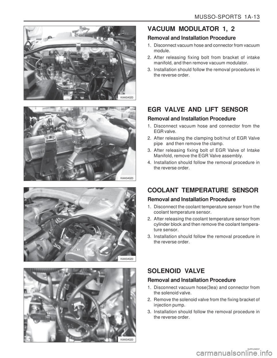
KAA5A020 EXHAUST GAS RECIRCULATION MODULE Removal and Installation Procedure
1. After releasing fixing screw of door scuff to the
passenger seat , remove the door scuff.
KAA5A020 2. After releasing fixing bolt of cowl side trim, remove
cowl side trim.
3. Remove pin of connector from the EGR module.
4. After releasing the fixing nut(3ea) of EGR module, remove the the EGR module.
5. Installation should follow the removal procedure in the reverse order.
THROTTLE POSITION SENSOR Removal Procedure 1. Disconnect the TPS connector from the TPS.
2. After releasing the fixing bolt, remove the TPS. Installation Procedure
1. Install temporary fixing bolt of TPS.
2. Install connector of TPS on the TPS.
3. Check the voltage of TPS by using SCAN-100.
4. Install completely fixing bolt of TPS.
Page 1325 of 1574

MUSSO-SPORTS 1A-13
SUPPLEMENT
KAA5A020
KAA5A020
KAA5A020VACUUM MODULATOR 1, 2 Removal and Installation Procedure
1. Disconnect vacuum hose and connector from vacuum
module.
2. After releasing fixing bolt from bracket of intake manifold, and then remove vacuum modulator.
3. Installation should follow the removal procedures in the reverse order.
KAA5A020 EGR VALVE AND LIFT SENSOR Removal and Installation Procedure
1. Disconnect vacuum hose and connector from the
EGR valve.
2. After releasing the clamping bolt/nut of EGR Valve pipe and then remove the clamp.
3. After releasing fixing bolt of EGR Valve of Intake Manifold, remove the EGR Valve assembly.
4. Installation should follow the removal procedure in the reverse order.
COOLANT TEMPERATURE SENSOR Removal and Installation Procedure
1. Disconnect the coolant temperature sensor from the coolant temperature sensor.
2. After releasing the coolant temperature sensor from cylinder block and then remove the coolant tempera- ture sensor.
3. Installation should follow the removal procedure in the reverse order.
SOLENOID VALVE Removal and Installation Procedure
1. Disconnect vacuum hose(3ea) and connector from the solenoid valve.
2. Remove the solenoid valve from the fixing bracket of injection pump.
3. Installation should follow the removal procedure in the reverse order.
Page 1346 of 1574
1A-34 MUSSO-SPORTS
SUPPLEMENT
15 IGN1
31
* ( ) : A/T
* A/T TPS, RPM Signal : TCU A5
30
GND
F24
LW A/T
TCU A5 Clutch SW
"1" TPSM/T
41 2
2 RPM Sensor
S201
1 3
LW GrW HUBER EGR ECU (K2004) BG
C R G BrB BrWLRG
10A
BAT+
F17
RY RY 3 9 28 62 61 81 10 29
1
4 6 0798 05 675 4 324 3 332 3 736
WR W WB BrW GR
WR W WB BrW GR BG BrG GL LG YL LB
WR Lift Sensor
EGR Valve Water Sensor
Temp EGR Modulator Exhanst Gas
RecirculationModulator Sol Valve
W WB BrW GR BG BrG GL LG YL LB
S201
8
12 10A
213 7 8
B
13(11) 14(12) 11(9) 12(10) 9(7) (10)8
C901 (C902)
C901
C108
C105
C104
G204
Ef 2 Ef 8
80A60A
C103
2
56 7 2 1
16 15 1411 10
4. HUBER EGR CIRCUIT(MUSSO SPORT)