Page 26 of 1574

GENERAL ENGINE INFORMATION 1A1-7
OIL LEAK DIAGNOSIS Most fluid oil leaks are easily located and repaired by visually finding the leak and replacing or repairing thenecessary parts. On some occasions a fluid leak may
be difficult to locate or repair. The following proceduresmay help you in locating and repairing most leaks. Finding the Leak
1. Identify the fluid. Determine whether it is engine oil,automatic transmission fluid, power steering fluid, etc.
2. Identify where the fluid is leaking from. 2.1 After running the vehicle at normal operating temperature, park the vehicle over a large sheet
of paper.
2.2 Wait a few minutes.
2.3 You should be able to find the approximate location of the leak by the drippings on the
paper.
3. Visually check around the suspected component. Check around all the gasket mating surfaces forleaks. A mirror is useful for finding leaks in areas thatare hard to reach.
4. If the leak still cannot be found, it may be necessary to clean the suspected area with a degreaser, steamor spray solvent.
4.1 Clean the area well.
4.2 Dry the area.
4.3 Operate the vehicle for several miles at normal operating temperature and varying speeds.
4.4 After operating the vehicle, visually check the suspected component.
4.5 If you still cannot locate the leak, try using the powder or black light and dye method.
Powder Method
1. Clean the suspected area.
2. Apply an aerosol-type powder (such as foot powder) to the suspected area.
3. Operate the vehicle under normal operating conditoins.
4. Visually inspect the suspected component. You should be able to trace the leak path over the white powder surface to the source.
Black Light and Dye Method A dye and light kit is available for finding leaks, Refer to the manufacturer's directions when using the kit.
1. Pour the specified amount of dye into the engine oil fill tube. 2. Operate the vehicle normal operating conditions as
directed in the kit.
3. Direct the light toward the suspected area. The dyed fluid will appear as a yellow path leading to the source.
Repairing the Leak Once the origin of the leak has been pinpointed and traced back to its source, the cause of the leak must be
determined n order for it to be repaired properly. If agasket is replaced, but the sealing flange is bent, the new gasket will not repair the leak. The bent flange must be repaired also. Before attempting to repair a leak,check for the following conditions and correct them asthey may cause a leak. Gaskets
� The fluid level/pressure is too high.
� The crankcase ventilation system is malfunctioning.
� The fasteners are tightened improperly or the threads are dirty or damaged.
� The flanges or the sealing surface is warped.
� There are scratches, burrs or other damage to thesealing surface.
� The gasket is damaged or worn.
� There is cracking or porosity of the component.
� An improper seal was used (where applicable).
Seals
� The fluid level/pressure is too high.
� The crankcase ventilation system is malfunctioning.
� The seal bore is damaged (scratched, burred or nicked).
� The seal is damaged or worn.
� Improper installation is evident.
� There are cracks in the components.
� The shaft surface is scratched, nicked or damaged.
� A loose or worn bearing is causing excess seal wear.
DIAGNOSIS
Page 306 of 1574
OM600 ENGINE MECHANICAL 1B3-41
8. Remove the air cleaner cover and element and thenremove the air cleaner housing.
9. Remove the oil return hose and plug.
Notice Cover them to prevent chips from coming into.
10. Unscrew the EGR pipe mounting bolts onto the exhaust manifold.
11. Remove the duct bracket from the cylinder head.
12. Unscrew the intake duct mounting bolts onto the intake manifold.
13. Separate the connecting rod from the control lever.
Page 684 of 1574

SECTION 1G3
OM600 ENGINE INTAKE & EXHAUST
Specifications . . . . . . . . . . . . . . . . . . . . . . . 1G3-1Fastener Tightening Specifications . . . . . . . . 1G3-1
Schematic and Routing Diagrams . . . . . . . 1G3-2 EGR Circuit . . . . . . . . . . . . . . . . . . . . . . . . . . 1G3-2
Maintenance and Repair . . . . . . . . . . . . . . 1G3-3
On-Vehicle Service . . . . . . . . . . . . . . . . . . . . 1G3-3 TABLE OF CONTENTS
Caution: Disconnect the negative battery cable before removing or installing any electrical unit or when a tool or equipment could easily come in contact with exposed electrical terminals. Disconnecting this cable will help prevent personal injury and damage to the vehicle. The ignition must also be in LOCK unless otherwisenoted.
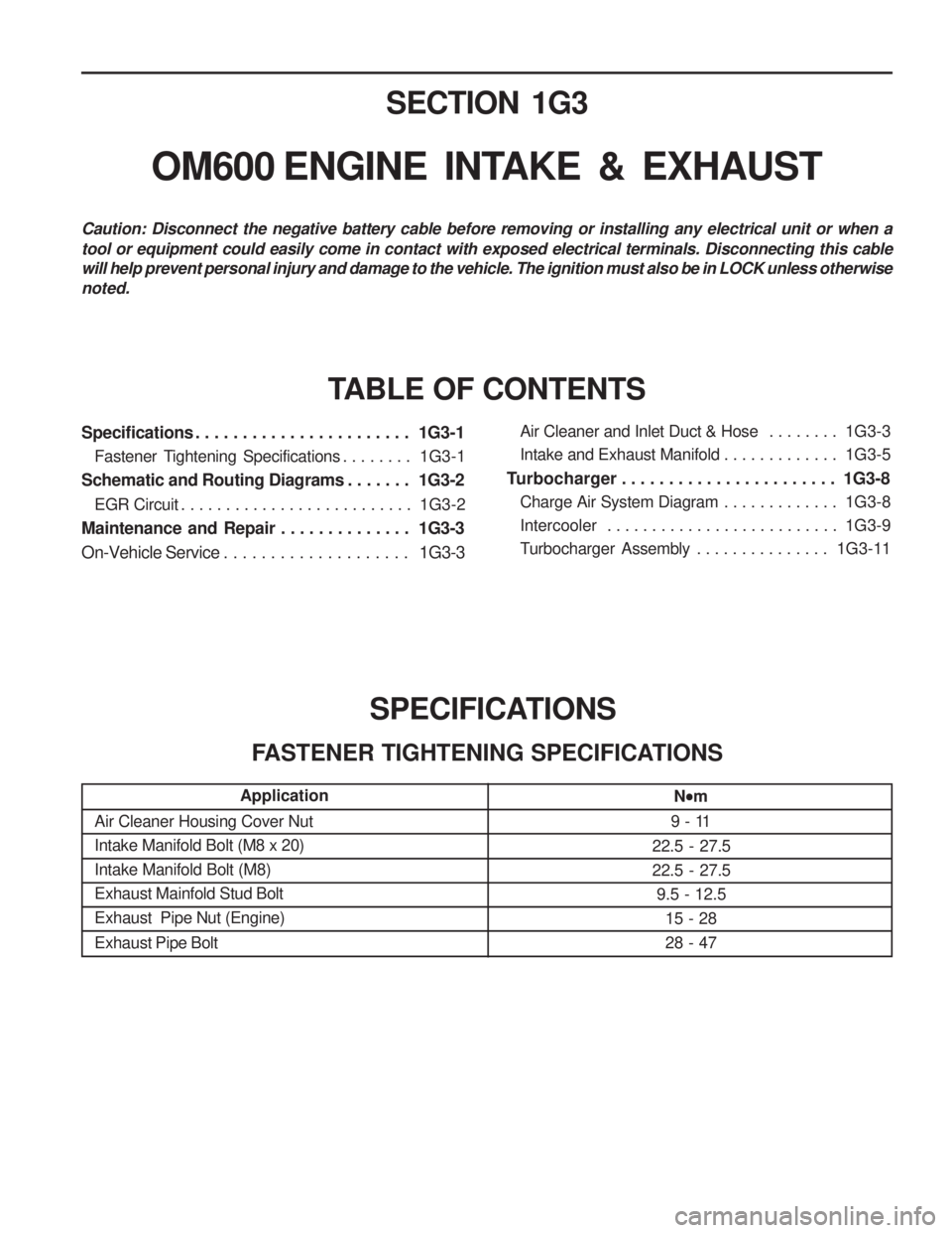
SPECIFICATIONS
FASTENER TIGHTENING SPECIFICATIONS
Application
Air Cleaner Housing Cover Nut Intake Manifold Bolt (M8 x 20)Intake Manifold Bolt (M8)Exhaust Mainfold Stud BoltExhaust Pipe Nut (Engine) Exhaust Pipe Bolt
N
m
9 - 11
22.5 - 27.5 22.5 - 27.5 9.5 - 12.5 15 - 2828 - 47
Air Cleaner and Inlet Duct & Hose . . . . . . . . 1G3-3
Intake and Exhaust Manifold . . . . . . . . . . . . . 1G3-5
Turbocharger . . . . . . . . . . . . . . . . . . . . . . . 1G3-8
Charge Air System Diagram . . . . . . . . . . . . . 1G3-8
Intercooler . . . . . . . . . . . . . . . . . . . . . . . . . . 1G3-9
Turbocharger Assembly . . . . . . . . . . . . . . . 1G3-11
Page 685 of 1574
1G3-2 OM600 ENGINE INTAKE & EXHAUSTSCHEMATIC AND ROUTING DIAGRAMS
EGR CIRCUIT
Page 719 of 1574

WHEEL ALIGNMENT 2B-9
GENERAL DESCRIPTION AND SYSTEM OPERATION
FOUR WHEEL ALIGNMENT CASTER Caster is the tilting 91 the uppermost point of the steering axis either forward or backward from the vertical when viewed from the side of the vehicle. A backward tilt is positive, and a forward tilt is negative. Caster influencesdirectional control of the steering but does not affect
tire wear. Weak springs or overloading a vehicle will affect
caster. One wheel with more positive caster will pull
toward the center of the car. This condition will cause the car to move or lean toward the side with the least
amount of positive caster. Caster is measured in degrees. CAMBER Camber is the tilting of the top of the tire from the vertical when viewed from the front of the vehicle. When thetires tilt outward, the camber is positive. When the tires tilt inward, the camber is negative. The camber angle is measured in degrees from the vertical. Camber
influences both directional control and tire wear.
If the vehicle has too much positive camber, the outside
shoulder of the tire will wear. If the vehicle has too much
negative camber, the inside shoulder of the tire will wear.
The first responsibility of engineering is to design safesteering and suspension systems. Each componentmust be strong enough to withstand and absorb extremepunishment. Both the steering system and the front and the rear suspension must function geometrically with thebody mass. The steering and the suspension systems require that the front wheels self-return and that the tire rolling effortand the road friction be held to a negligible force in orderto allow the customer to direct the vehicle with the least effort and the most comfort. A complete wheel alignment check should include
measurements of the rear toe and camber. Four-wheel alignment assures that all four wheels will be running in precisely the same direction. When the vehicle is geometrically aligned, fuel economy and tire life are at their peak, and steering andperformance are maximized. TOE
Toe-in is the turning in of the tires, while toe-out is the turning out of the tires from the geometric centerline or thrust line. The toe ensures parallel rolling of the wheels. The toe serves to offset the small deflections of the wheel support system which occur when the vehicle is rollingforward. The specified toe angle is the setting whichachieves 0 degrees of toe when the vehicle is moving. Incorrect toe-in or toe-out will cause tire wear and
reduced fuel economy. As the individual steering andsuspension components wear from vehicle mileage,
additional toe will be needed to compensate for the wear. Always correct the toe dimension last.
Page 853 of 1574
4F-24 ANTILOCK BRAKE SYSTEM ABS/ABD 5.3 Pressure Increased
1 Master Cylinder
2 Hydraulic Unit
3 Damping Chamber
4 Return Pump
5 Return Pump Motor
6 Accumulator Chamber7 Inlet Valve for Each Wheel
8 Outlet Valve for Each Wheel
9 Wheel
10 Prime Valve (ASV) 11 Pilot Valve (USV)
12 Check V alve
13 ISD (Integrated Suction Damper)
Page 854 of 1574
ANTILOCK BRAKE SYSTEM 4F-25
Pressure Decreased
1 Master Cylinder
2 Hydraulic Unit
3 Damping Chamber
4 Return Pump
5 Return Pump Motor
6 Accumulator Chamber7 Inlet Valve for Each Wheel
8 Outlet Valve for Each Wheel
9 Wheel
10 Prime Valve (ASV) 11 Pilot Valve (USV)
12 Check V alve
13 ISD (Integrated Suction Damper)
Page 855 of 1574
4F-26 ANTILOCK BRAKE SYSTEM Pressure Maintained (Hold)
1 Master Cylinder
2 Hydraulic Unit
3 Damping Chamber
4 Return Pump
5 Return Pump Motor
6 Accumulator Chamber7 Inlet Valve for Each Wheel
8 Outlet Valve for Each Wheel
9 Wheel
10 Prime Valve (ASV) 11 Pilot Valve (USV)
12 Check V alve
13 ISD (Integrated Suction Damper)