Page 1059 of 1574
TRANSFER CASE (PART TIME 4408) 5D1-7
No.Defective Code
Malfunctioning Part
6
7
Selector Switch
Motor Positon Sensor
4WD CHECKLight ONOFF
Defective Code
4WD CHECK Light ON OFF
Defective Code
Page 1060 of 1574
5D1-8 TRANSFER CASE (PART TIME 4408) SELF-DIAGNOSIS TEST
Test Procedure
1. Connect the scanner harness connector to the enginecompartment diagnosis socket.
2. Turn the ignition switch to "ON" position.
3. Select "Electronic control vehicle diagnosis" from the function selection display and press "Enter".
4. Select "Musso" from vehicle model selection display and press "Enter".
5. Select "TCCU" from control system selection display and press "Enter".
6. Select "TCCU Part Time" from TCCU diagnosis selection display. Notice
Check sensor valve output display if necessary.
7 . Select "Self-diagnosis" from diagnosis items selection display.
8. Turn the ignition switch to "OFF" position and press "ENTER". Turn the ignition swtich to "ON" position again and press "ENTER".
9. Determine fault code and check the defective component.
Notice Refer to self-diagnosis list.
Page 1067 of 1574

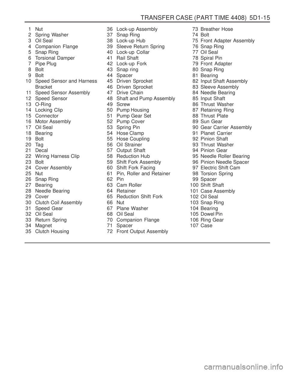
TRANSFER CASE (PART TIME 4408) 5D1-15
1 Nut
2 Spring Washer
3 Oil Seal
4 Companion Flange
5 Snap Ring
6 Torsional Damper
7 Pipe Plug
8 Bolt
9 Bolt
10 Speed Sensor and Harness
Bracket
11 Speed Sensor Assembly
12 Speed Sensor
13 O-Ring
14 Locking Clip
15 Connector
16 Motor Assembly
17 Oil Seal
18 Bearing
19 Bolt
20 Tag
21 Decal
22 Wiring Harness Clip
23 Bolt
24 Cover Assembly
25 Nut
26 Snap Ring
27 Bearing
28 Needle Bearing
29 Cover
30 Clutch Coil Assembly
31 Speed Gear
32 Oil Seal
33 Return Spring
34 Magnet
35 Clutch Housing 36 Lock-up Assembly
37 Snap Ring
38 Lock-up Hub
39 Sleeve Return Spring
40 Lock-up Collar
41 Rail Shaft
42 Lock-up Fork
43 Snap ring
44 Spacer
45 Driven Sprocket
46 Driven Sprocket
47 Drive Chain
48 Shaft and Pump Assembly
49 Screw
50 Pump Housing
51 Pump Gear Set
52 Pump Cover
53 Spring Pin
54 Hose Clamp
55 Hose Coupling
56 Oil Strainer
57 Output Shaft
58 Reduction Hub
59 Shift Fork Assembly
60 Shift Fork Facing
61 Pin, Roller and Retainer
62 Pin
63 Cam Roller
64 Retainer
65 Reduction Shift Fork
66 Nut
67 Plane Washer
68 Oil Seal
70 Companion Flange
71 Spacer
72 Front Output Assembly 73 Breather Hose
74 Bolt
75 Front Adapter Assembly
76 Snap Ring
77 Oil Seal
78 Spiral Pin
79 Front Adapter
80 Snap Ring
81 Bearing
82 Input Shaft Assembly
83 Sleeve Assembly
84 Needle Bearing
85 Input Shaft
86 Thrust Washer
87 Retaining Ring
88 Thrust Plate
89 Sun Gear
90 Gear Carrier Assembly
91 Planet Carrier
92 Pinion Shaft
93 Thrust Washer
94 Pinion Gear
95 Needle Roller Bearing
96 Pinion Needle Spacer
97 Electric Shift Cam
98 Torsion Spring
99 Spacer
100 Shift Shaft
101 Case Assembly
102 Oil Seal
103 Snap Ring
104 Bearing
105 Dowel Pin
106 Ring Gear
107 Case
Page 1068 of 1574
5D1-16 TRANSFER CASE (PART TIME 4408)
Disassembly Procedure
1. Holding the companion flange, remove the nut and washerand then remove the companion flange and oil seal.
2. Remove the 2 plugs from the cover.
1 Nut
2 Washer
3 Oil Seal
4 Companion Flange
5 Plug
2 5 Cover
6 Bolt
7 Washer
8 Bolt
9 Sensor and Harness Bracket
10 Sensor Assembly 11 Speed Sensor
12 O-ring
13 Motor Assembly
2 5 Cover
1. Remove the bolt, washer,3 bolts and harness bracket.
2. Remove the sensor assembly and remove the O-ring from
the speed sensor.
3. Remove the motor assembly.
Page 1086 of 1574
5D1-34 TRANSFER CASE (PART TIME 4408)
External Electric Shift
1. Align the motor with shift shaft and position the motorassembly onto the cover.
2. Install the motor to the shift shaft and contact cover androtate the motor clockwise direction to check correctengagement.
6 Bolt
7 Washer
8 Bolt
9 Sensor and Harness Bracket
10 Sensor Assembly
14 Speed Sensor
12 O-ring
13 Motor Assembly
2 5 Cover
13 Motor Assembly
103 Shift Shaft
3. Insert the 0-ring on the speed sensor speed sensor
assembly to the cover.
4. Install the bracket to the motor assembly and tighten 3bolts.
Tightening Torque 8 -11 Nm
Page 1090 of 1574

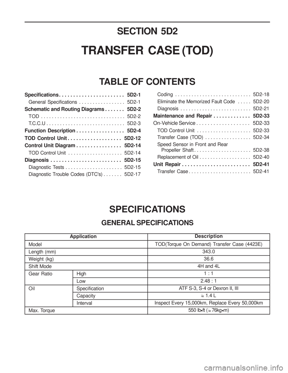
SECTION 5D2
TRANSFER CASE (TOD)
Specifications . . . . . . . . . . . . . . . . . . . . . . . 5D2-1General Specifications . . . . . . . . . . . . . . . . . 5D2-1
Schematic and Routing Diagrams . . . . . . . 5D2-2 TOD . . . . . . . . . . . . . . . . . . . . . . . . . . . . . . . 5D2-2
T.C.C.U . . . . . . . . . . . . . . . . . . . . . . . . . . . . . 5D2-3
Function Description . . . . . . . . . . . . . . . . . 5D2-4
TOD Control Unit . . . . . . . . . . . . . . . . . . . 5D2-12
Control Unit Diagram . . . . . . . . . . . . . . . . 5D2-14
TOD Control Unit . . . . . . . . . . . . . . . . . . . . 5D2-14
Diagnosis . . . . . . . . . . . . . . . . . . . . . . . . . 5D2-15 Diagnostic Tests . . . . . . . . . . . . . . . . . . . . . 5D2-15
Diagnostic Trouble Codes (DTC's) . . . . . . . 5D2-17
TABLE OF CONTENTS
SPECIFICATIONS
GENERAL SPECIFICATIONS
ModelLength (mm)Weight (kg)Shift ModeGear Ratio Oil
Max. Torque
High Low SpecificationCapacityInterval TOD(Torque On Demand) Transfer Case (4423E)
343.036.6
4H and 4L
1 : 1
2.48 : 1
ATF S-3, S-4 or Dexron II, III 1.4 L
Inspect Every 15,000km, Replace Every 50,000km 550 lbft ( 76kg m)
.
= .
.
= .
Application Description
Coding . . . . . . . . . . . . . . . . . . . . . . . . . . . . 5D2-18
Eliminate the Memorized Fault Code . . . . .
5D2-20
Diagnosis . . . . . . . . . . . . . . . . . . . . . . . . . . 5D2-21
Maintenance and Repair . . . . . . . . . . . . . 5D2-33
On-Vehicle Service . . . . . . . . . . . . . . . . . . . 5D2-33
TOD Control Unit . . . . . . . . . . . . . . . . . . . . 5D2-33
Transfer Case (TOD) . . . . . . . . . . . . . . . . . 5D2-34
Speed Sensor in Front and Rear Propeller Shaft . . . . . . . . . . . . . . . . . . . . . 5D2-38
Replacement of Oil . . . . . . . . . . . . . . . . . . . 5D2-40
Unit Repair . . . . . . . . . . . . . . . . . . . . . . . . 5D2-41 Transfer Case . . . . . . . . . . . . . . . . . . . . . . . 5D2-41
Page 1093 of 1574

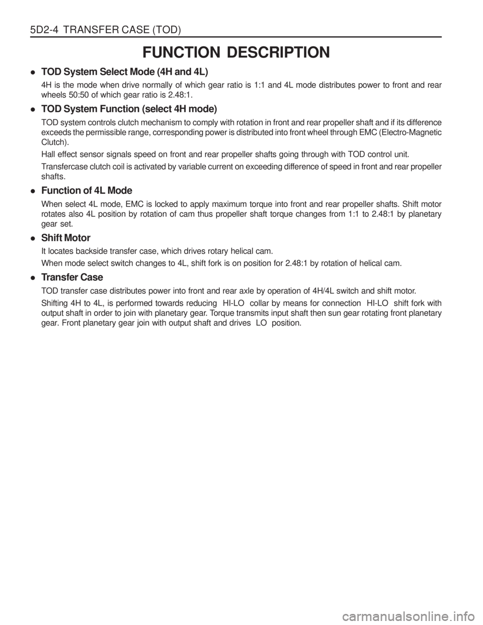
5D2-4 TRANSFER CASE (TOD)FUNCTION DESCRIPTION
� TOD System Select Mode (4H and 4L) 4H is the mode when drive normally of which gear ratio is 1:1 and 4L mode distributes power to front and rear wheels 50:50 of which gear ratio is 2.48:1.
� TOD System Function (select 4H mode) TOD system controls clutch mechanism to comply with rotation in front and rear propeller shaft and if its difference exceeds the permissible range, corresponding power is distributed into front wheel through EMC (Electro-MagneticClutch). Hall effect sensor signals speed on front and rear propeller shafts going through with TOD control unit.
Transfercase clutch coil is activated by variable current on exceeding difference of speed in front and rear propeller shafts.
� Function of 4L Mode When select 4L mode, EMC is locked to apply maximum torque into front and rear propeller shafts. Shift motor rotates also 4L position by rotation of cam thus propeller shaft torque changes from 1:1 to 2.48:1 by planetarygear set.
� Shift Motor It locates backside transfer case, which drives rotary helical cam. When mode select switch changes to 4L, shift fork is on position for 2.48:1 by rotation of helical cam.
� Transfer Case
TOD transfer case distributes power into front and rear axle by operation of 4H/4L switch and shift motor. Shifting 4H to 4L, is performed towards reducing HI-LO collar by means for connection HI-LO shift fork with
output shaft in order to join with planetary gear. Torque transmits input shaft then sun gear rotating front planetary
gear. Front planetary gear join with output shaft and drives LO position.
Page 1094 of 1574

TRANSFER CASE (TOD) 5D2-5
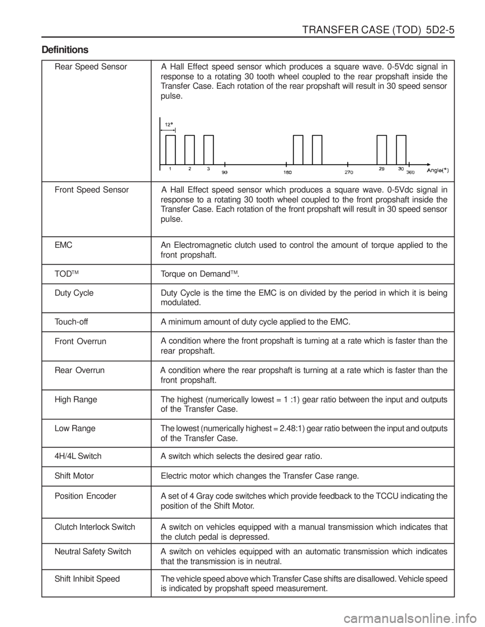
Definitions
Rear Speed Sensor A Hall Effect speed sensor which produces a square wave. 0-5Vdc signal inresponse to a rotating 30 tooth wheel coupled to the rear propshaft inside the
Transfer Case. Each rotation of the rear propshaft will result in 30 speed sensor pulse.
Front Speed Sensor A Hall Effect speed sensor which produces a square wave. 0-5Vdc signal in response to a rotating 30 tooth wheel coupled to the front propshaft inside the
Transfer Case. Each rotation of the front propshaft will result in 30 speed sensor pulse.
EMC An Electromagnetic clutch used to control the amount of torque applied to the front propshaft.
TOD TM
Torque on DemandTM
.
Duty Cycle Duty Cycle is the time the EMC is on divided by the period in which it is being modulated.
Touch-off A minimum amount of duty cycle applied to the EMC.
Front OverrunA condition where the front propshaft is turning at a rate which is faster than the rear propshaft.
Rear Overrun A condition where the rear propshaft is turning at a rate which is faster than the
front propshaft.
High Range The highest (numerically lowest = 1 :1) gear ratio between the input and outputsof the Transfer Case.
Low Range The lowest (numerically highest = 2.48:1) gear ratio between the input and outputs
of the Transfer Case.
4H/4L Switch A switch which selects the desired gear ratio.
Shift Motor Electric motor which changes the Transfer Case range.
Position Encoder A set of 4 Gray code switches which provide feedback to the TCCU indicating theposition of the Shift Motor.
Clutch Interlock Switch A switch on vehicles equipped with a manual transmission which indicates that the clutch pedal is depressed.
Neutral Safety Switch A switch on vehicles equipped with an automatic transmission which indicatesthat the transmission is in neutral.
Shift Inhibit Speed The vehicle speed above which Transfer Case shifts are disallowed. Vehicle speedis indicated by propshaft speed measurement.