2003 SSANGYONG MUSSO sensor
[x] Cancel search: sensorPage 1095 of 1574

5D2-6 TRANSFER CASE (TOD) Input/Output diagram TOD control unit and main wiring harness is linked by 30 pin
connector. Each pin joins with switche and actuator whosedetails refer to the below diagram.
Battery Power
Ignition ON/OFF
Position Encoder 1
Position Encoder 2
Position Encoder 3
Position Encoder 4
4H / 4L Switch Signal
A/T “N” Position Signal
Speed / TPS Supply
Front Speed Sensor Input
Rear Speed Sensor Input
ABS Operation Signal
Brake Switch Signal
4 5271028309241611292526
19 CAN H
CAN L
Shift Motor output port (LO-HI)
Shift Motor output port (HI-LO)
EMC
'4L' Indicator
Position Return
'4WD CHECK' IND
TPS/speed Sensor Ground (Speed / TPS Return)
2 13216713
1514
K-Line
20
22
23
17 18
Page 1096 of 1574

TRANSFER CASE (TOD) 5D2-7
1. K-LINE : Communication line for coding and diagnosis with SCANNER.
Classification of Pin No.
Classification
Pin No. Pin Name Description
Power Supply 17,18
Ground
TOD control unit ground
4,19 Battery TOD control unit battery supply : (Fuse No 13,20A)
5 Ignition Ignition ON / OFF
27 Position 1
Position encoder 1 : check of shift motor position
10 Position 2 Position encoder 2 : check of shift motor position
28 Position 3
Position encoder 3 : check of shift motor position
30 Position 4
Position encoder 4 : check of shift motor position
9 4H/4L Switch Transfer case mode input
24 Auto T/M Neutral Check of neutral gear position in Auto T/M 16 Speed 5V supply (TPS / speed sensor)
11 Front Speed
Front speed sensor signal input
Signal Input
29 Rear Speed Rear speed sensor signal input
25 ABS Operation
ABS ON / OFF
6 Position Return
Position encoder ground
13 Speed / TPS Return Ground for speed sensor / TPS
2 2 CAN-L CAN bus low line
23 CAN-H
CAN bus high line
2,15 Motor LO-HI Motor output port
- LO to HI : join with battery
- HI to LO (or motor brake) : join with ground
1,14 Motor HI-LO Motor output port
- HI to LO : join with battery
- LO to HI (or motor brake) : join with ground
3 EMC TOD output
Signal Output
21 4L Illumination Illuminates
“4L ” indicator
7 Diagnosis Display
4WD check lamp illuminator
- Upon defect ; Ground circuit
20K-LINE1)
Diagnosis
Page 1098 of 1574
TRANSFER CASE (TOD) 5D2-9
4H/4L Switch Input4H 4H 4H 4H 4H 4H4H4H4H
4L 4L 4L4L 4L 4L4L4L 4L
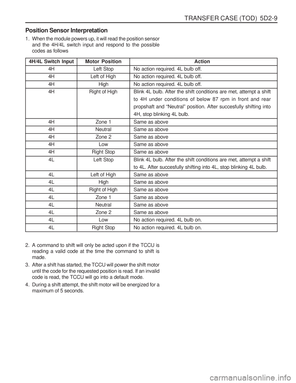
Position Sensor Interpretation
1. When the module powers up, it will read the position sensor
and the 4H/4L switch input and respond to the possible codes as follows
2. A command to shift will only be acted upon if the TCCU is reading a valid code at the time the command to shift ismade.
3. After a shift has started, the TCCU will power the shift motor until the code for the requested position is read. If an invalidcode is read, the TCCU will go into a default mode.
4. During a shift attempt, the shift motor will be energized for a maximum of 5 seconds. Motor Position
Left Stop
Left of High
High
Right of High
Zone 1
Neutral
Zone 2 Low
Right Stop
Left Stop
Left of High High
Right of High
Zone 1
Neutral Zone 2 Low
Right Stop Action
No action required. 4L bulb off. No action required. 4L bulb off. No action required. 4L bulb off. Blink 4L bulb. After the shift conditions are met, attempt a shiftto 4H under conditions of below 87 rpm in front and rearpropshaft and “Neutral ” position. After succesfully shifting into
4H, stop blinking 4L bulb. Same as above Same as aboveSame as aboveSame as aboveSame as above Blink 4L bulb. After the shift conditions are met, attempt a shift to 4L. After succesfully shifting into 4L, stop blinking 4L bulb.Same as aboveSame as aboveSame as above Same as above Same as aboveSame as aboveNo action required. 4L bulb on. No action required. 4L bulb on.
Page 1099 of 1574
5D2-10 TRANSFER CASE (TOD) Electric Shift System Operation
The Electric Shift System is responsible for changing the Transfer Case gear ratio by controlling the electric shift
motor. The TCCU monitors the 4H/4L switch, neutral switch, speed sensors, position encoder, and ignition switch. A range change is initiated when
1. The 4H/4L Switch is changed from 4H to 4L or from 4L to 4H.
2. The motor position (as indicated by the position encoder) does not match the 4H/4L Switch immediately after theignition is turned on.
1. Shift Criteria When a range change is initiated a Diagnostic Test will be completed on the motor, speed sensors, and position
encoder. If the Diagnostic Test fails, the shift will not be attempted. If all components are operating properly, theTCCU will attempt a range change after the following shift criteria are met:
a. The transmission is in neutral for 2 seconds after the shift is requested.
b. Both propshaft speeds are below 87 rpm (2580 pulses/minute).
If the transmission is taken out of neutral before 2 seconds has elapsed, or either propshaft speed increases above the limit, the shift will be suspended and the 4L Indicator will continue to blink until the criteria are met again or the 4H/4L Switch is returned to the original position.
2. Range Change When the shift criteria are met, the motor is rotated in the appropriate direction (as determined by the selectorswitch) until one of the following occurs:
a. The motor reaches its destination.
b. The motor is on for 5 seconds without reaching its destination. The shift has failed and the TCCU will respond as default mode.
c. A fault occurs with either the motor or position encoder. Refer to the diagnosis requirement.
When the motor is energized, the Ignition, 4H/4L Switch, propshaft speeds, and transmission neutral inputs are ignored.
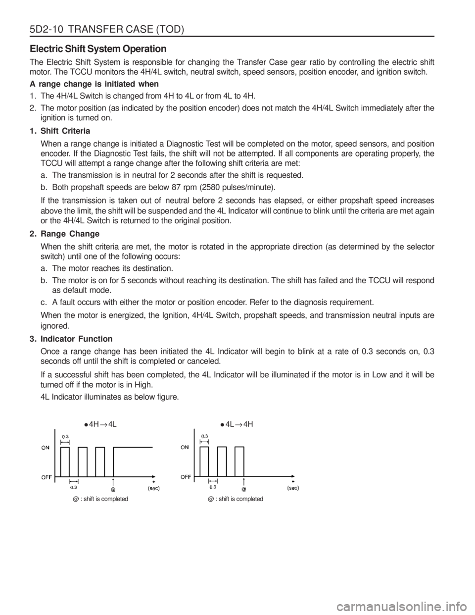
3. Indicator Function Once a range change has been initiated the 4L Indicator will begin to blink at a rate of 0.3 seconds on, 0.3 seconds off until the shift is completed or canceled.
If a successful shift has been completed, the 4L Indicator will be illuminated if the motor is in Low and it will be turned off if the motor is in High. 4L Indicator illuminates as below figure.
4H
� 4L
@ : shift is completed
4L
� 4H
@ : shift is completed
Page 1102 of 1574
TRANSFER CASE (TOD) 5D2-13
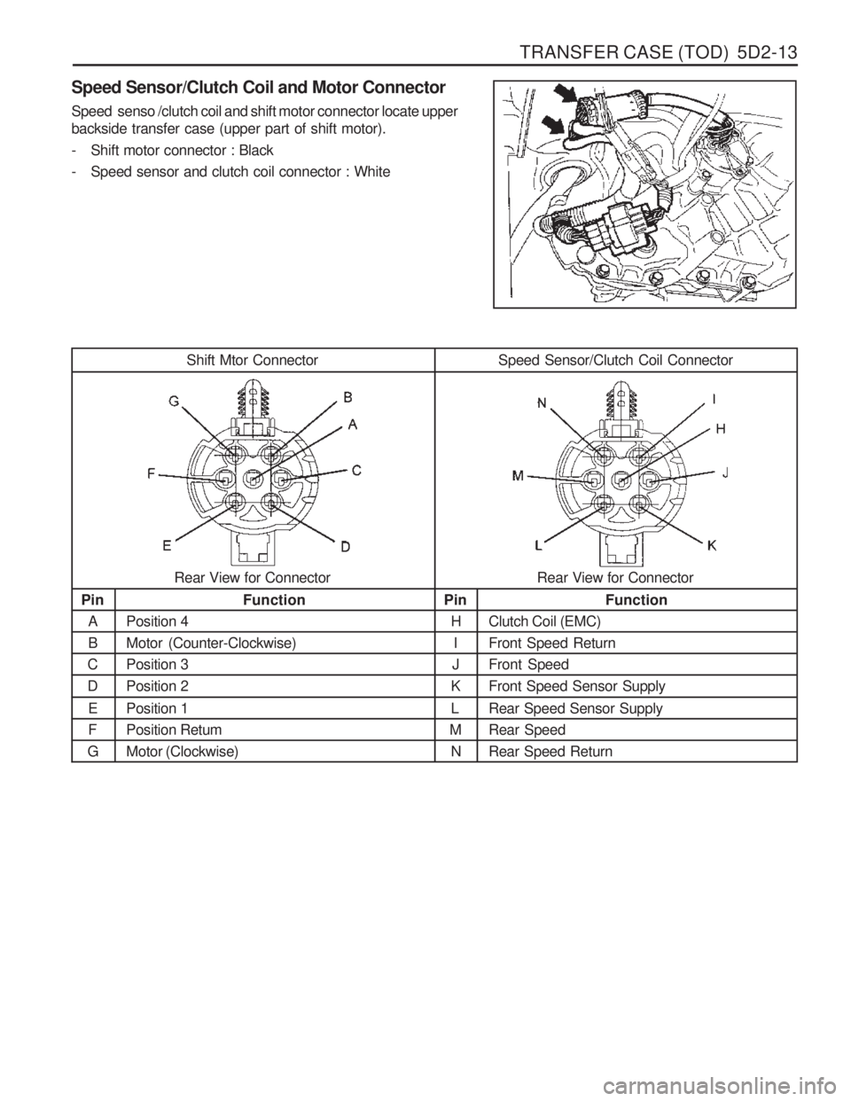
Speed Sensor/Clutch Coil and Motor Connector Speed senso /clutch coil and shift motor connector locate upper backside transfer case (upper part of shift motor).
- Shift motor connector : Black
- Speed sensor and clutch coil connector : White
Shift Mtor Connector Speed Sensor/Clutch Coil ConnectorRear View for Connector
Pin A B
CD
EF
G Function
Position 4Motor (Counter-Clockwise)Position 3Position 2 Position 1 Position RetumMotor (Clockwise) Pin
HI
J
K L
M N Function
Clutch Coil (EMC) Front Speed ReturnFront SpeedFront Speed Sensor Supply Rear Speed Sensor Supply Rear SpeedRear Speed Return
Rear View for Connector
Page 1105 of 1574
5D2-16 TRANSFER CASE (TOD)g. If the shift motor/position encoder assembly failure (other than a motor failure which occurs when the motor isenergized) recovers continuously for one second the TCCU will function normally. The “4WD CHECK ” lamp is
turned off but the fault code will remain in memory.
h. A motor failure (i.e. open or short circuit) which occurs when the motor is energized can only be cleared by cycling the ignition off-on.
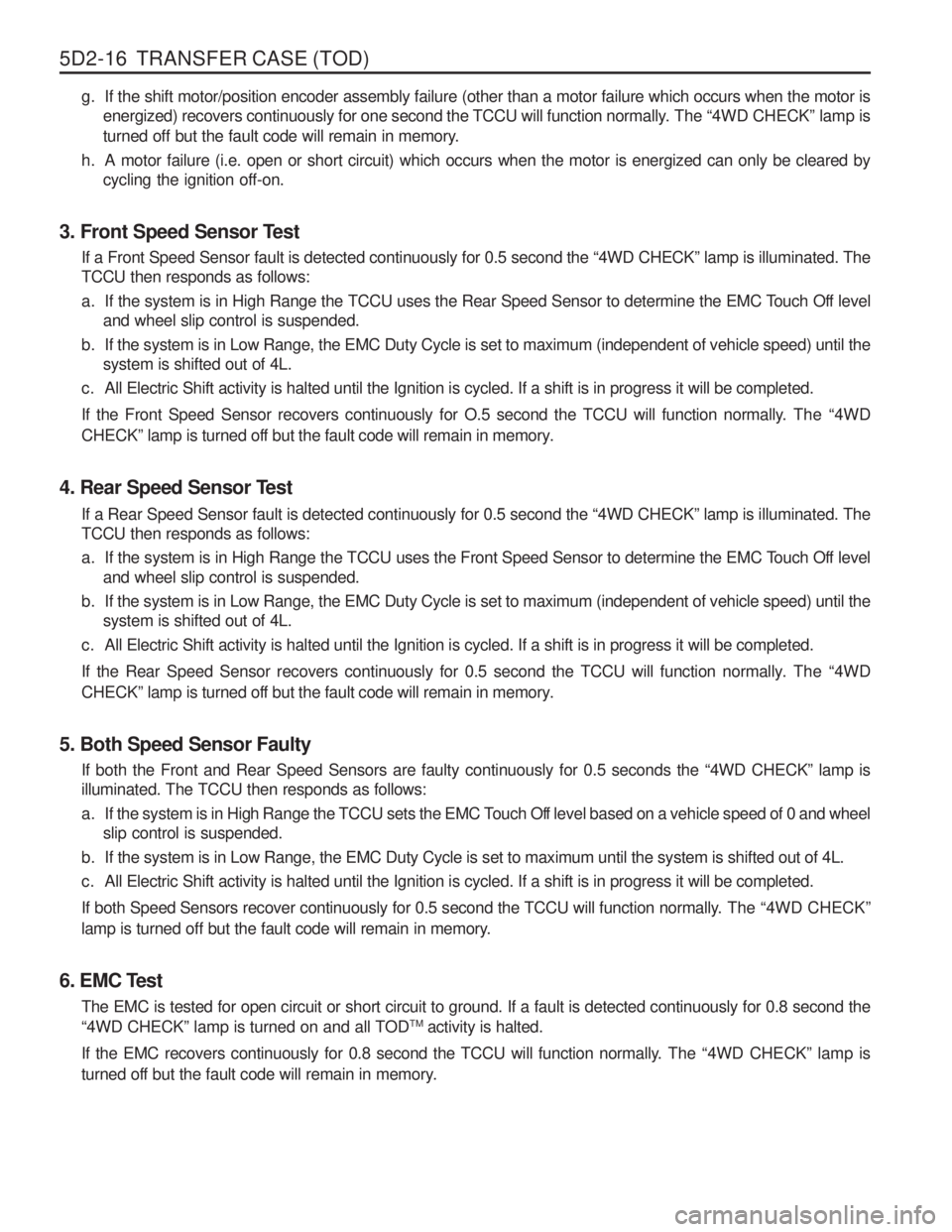
3. Front Speed Sensor Test If a Front Speed Sensor fault is detected continuously for 0.5 second the “4WD CHECK ” lamp is illuminated. The
TCCU then responds as follows:
a. If the system is in High Range the TCCU uses the Rear Speed Sensor to determine the EMC Touch Off level and wheel slip control is suspended.
b. If the system is in Low Range, the EMC Duty Cycle is set to maximum (independent of vehicle speed) until the system is shifted out of 4L.
c. All Electric Shift activity is halted until the Ignition is cycled. If a shift is in progress it will be completed.
If the Front Speed Sensor recovers continuously for O.5 second the TCCU will function normally. The “4WD
CHECK ” lamp is turned off but the fault code will remain in memory.
4. Rear Speed Sensor Test If a Rear Speed Sensor fault is detected continuously for 0.5 second the “4WD CHECK ” lamp is illuminated. The
TCCU then responds as follows:
a. If the system is in High Range the TCCU uses the Front Speed Sensor to determine the EMC Touch Off level and wheel slip control is suspended.
b. If the system is in Low Range, the EMC Duty Cycle is set to maximum (independent of vehicle speed) until the system is shifted out of 4L.
c. All Electric Shift activity is halted until the Ignition is cycled. If a shift is in progress it will be completed.
If the Rear Speed Sensor recovers continuously for 0.5 second the TCCU will function normally. The “4WD
CHECK ” lamp is turned off but the fault code will remain in memory.
5. Both Speed Sensor Faulty If both the Front and Rear Speed Sensors are faulty continuously for 0.5 seconds the “4WD CHECK ” lamp is
illuminated. The TCCU then responds as follows:
a. If the system is in High Range the TCCU sets the EMC Touch Off level based on a vehicle speed of 0 and wheel slip control is suspended.
b. If the system is in Low Range, the EMC Duty Cycle is set to maximum until the system is shifted out of 4L.
c. All Electric Shift activity is halted until the Ignition is cycled. If a shift is in progress it will be completed.
If both Speed Sensors recover continuously for 0.5 second the TCCU will function normally. The “4WD CHECK ”
lamp is turned off but the fault code will remain in memory.
6. EMC Test The EMC is tested for open circuit or short circuit to ground. If a fault is detected continuously for 0.8 second the “4WD CHECK ” lamp is turned on and all TOD TM
activity is halted.
If the EMC recovers continuously for 0.8 second the TCCU will function normally. The “4WD CHECK ” lamp is
turned off but the fault code will remain in memory.
Page 1106 of 1574
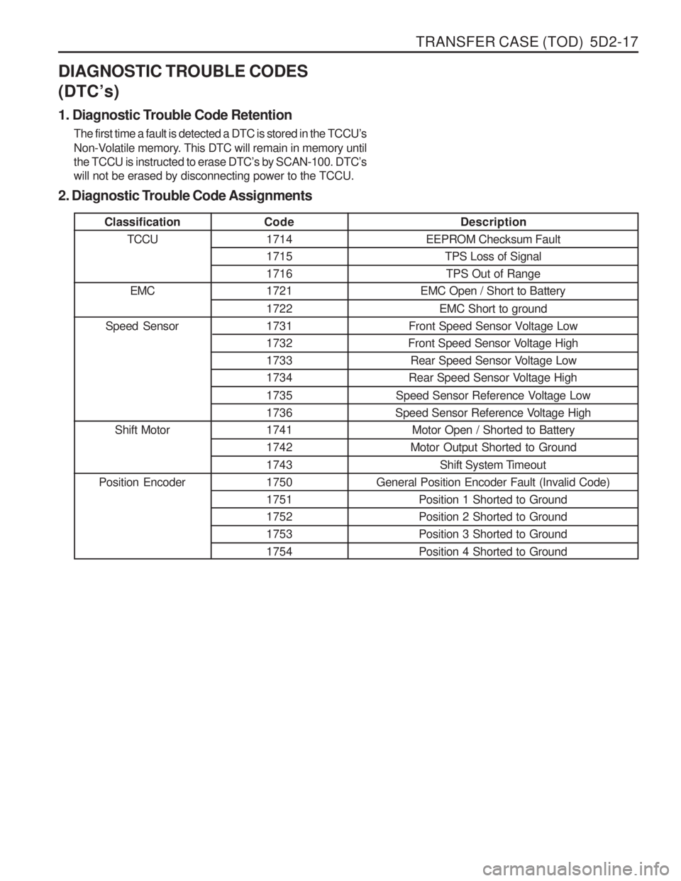
TRANSFER CASE (TOD) 5D2-17
ClassificationTCCU
EMC
Speed Sensor
Shift Motor
Position Encoder
DIAGNOSTIC TROUBLE CODES (DTC
’s)
1. Diagnostic Trouble Code Retention The first time a fault is detected a DTC is stored in the TCCU ’s
Non-Volatile memory. This DTC will remain in memory until the TCCU is instructed to erase DTC ’s by SCAN-100. DTC ’s
will not be erased by disconnecting power to the TCCU.
2. Diagnostic Trouble Code AssignmentsCode 1714 171517161721 1722 1731173217331734 1735 173617411742 1743 1750175117521753 1754 Description
EEPROM Checksum Fault TPS Loss of Signal
TPS Out of Range
EMC Open / Short to Battery
EMC Short to ground
Front Speed Sensor Voltage Low
Front Speed Sensor Voltage High
Rear Speed Sensor Voltage Low
Rear Speed Sensor Voltage High
Speed Sensor Reference Voltage Low
Speed Sensor Reference Voltage High Motor Open / Shorted to Battery
Motor Output Shorted to Ground
Shift System Timeout
General Position Encoder Fault (Invalid Code) Position 1 Shorted to Ground Position 2 Shorted to GroundPosition 3 Shorted to Ground Position 4 Shorted to Ground
Page 1113 of 1574
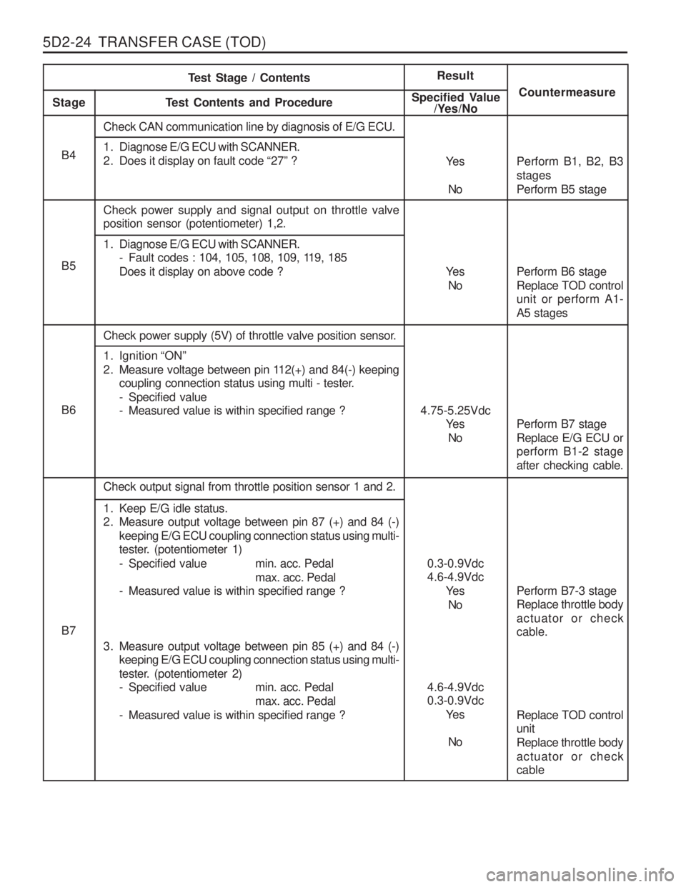
5D2-24 TRANSFER CASE (TOD)
Ye sNo
B4
B5
Ye s
No
B6 4.75-5.25Vdc
Ye s
No
B7 0.3-0.9Vdc 4.6-4.9Vdc
Ye s
No
4.6-4.9Vdc0.3-0.9Vdc Ye s
No
Test Stage / Contents
Result
Stage T est Contents and Procedure Specified Value
/Yes/No Countermeasure
Check CAN communication line by diagnosis of E/G ECU.
1. Diagnose E/G ECU with SCANNER.
2. Does it display on fault code
“27 ” ?
Check power supply and signal output on throttle valve position sensor (potentiometer) 1,2.
1. Diagnose E/G ECU with SCANNER. - Fault codes : 104, 105, 108, 109, 119, 185 Does it display on above code ?
Check power supply (5V) of throttle valve position sensor.
1. Ignition “ON ”
2. Measure voltage between pin 112(+) and 84(-) keeping coupling connection status using multi - tester.
- Specified value
- Measured value is within specified range ?
Check output signal from throttle position sensor 1 and 2.
1. Keep E/G idle status.
2. Measure output voltage between pin 87 (+) and 84 (-) keeping E/G ECU coupling connection status using multi-
tester. (potentiometer 1)
- Specified value min. acc. Pedal max. acc. Pedal
- Measured value is within specified range ?
3. Measure output voltage between pin 85 (+) and 84 (-) keeping E/G ECU coupling connection status using multi-
tester. (potentiometer 2)
- Specified value min. acc. Pedal
max. acc. Pedal
- Measured value is within specified range ? Replace TOD control unit Replace throttle bodyactuator or check cable
Perform B1, B2, B3 stagesPerform B5 stage Perform B6 stage Replace TOD control unit or perform A1- A5 stages Perform B7 stage Replace E/G ECU or perform B1-2 stage after checking cable. Perform B7-3 stage Replace throttle body actuator or check cable.