2003 PONTIAC BONNEVILLE engine
[x] Cancel search: enginePage 108 of 418
Programming the HomeLinkB
Transmitter
Do not use the HomeLink@ Transmitter with any garage
door opener that does not have the “stop and reverse”
feature. This includes any garage door opener model
manufactured before April
1, 1982.
Keep the original transmitter for use in other vehicles as
well as for future HomeLink@ programming. It is also
recommended that upon the sale of the vehicle,
the programmed HomeLink@ buttons should be erased
for security purposes. Refer to “Erasing HomeLink@
Buttons” or, for assistance, contact HomeLink@ on the
internet at: www.homelink.com or by calling
1 -800-355-351 5.
Be sure that people and objects are clear of the garage
door or gate operator you are programming. When
programming a garage door, it is advised to park outside
of the garage.
It is recommended that a new battery be installed in
your hand-held transmitter for quicker and more
accurate transmission of the radio frequency. Your vehicle’s engine should
be turned
off while
programming the transmitter. Follow these steps to
program up to three channels:
1. Press and hold down the two outside buttons,
releasing only when the indicator light begins to
flash, after
20 seconds. Do not hold down the
buttons for longer than
30 seconds and do not
repeat this step to program
a second and/or third
transmitter to the remaining two HomeLink@ buttons.
2. Position the end of your hand-held transmitter about
1 to 3 inches (3 to 8 cm) away from the HomeLink@
buttons while keeping the indicator light in view.
3. Simultaneously press and hold both the desired
button on HomeLink@ and the hand-held transmitter
button.
Do not release the buttons until Step 4
has been completed.
Some entry gates and garage door openers may
require you to substitute Step
3 with the procedure
noted in “Gate Operator and Canadian
Programming” later in this section.
4. The indicator light wiii tiasn siowiy at iirsi and iilerl
rapidly after HomeLink@ successfully receives the
frequency signal from the hand-held transmitter.
Release both buttons.
2-43
Page 116 of 418
Section 3 Instrument Panel
Instrument Panel Overview ............................... 3.4
Hazard Warning Flashers
................................ 3.5
Other Warning Devises
................................... 3.6
Horn
............................................................. 3.6
Tilt Wheel
..................................................... 3.6
Turn SignaVMultifunction Lever
......................... 3.7
Exterior Lamps
............................................. 3.13
Interior Lamps
.............................................. 3.16
Head-Up Display (HUD)
................................. 3-21
Accessory Power Outlets
............................... 3.23
Ashtrays and Cigarette Lighter
........................ 3.24
Ciimate Controls ............................................ 3.25
Climate Control System ................................. 3.25
Automatic Climate Control System
................... 3.28
Outlet Adjustment
......................................... 3.32
Climate Controls Personalization
..................... 3.33
Warning Lights, Gages and Indicators ............. 3.34
Instrument Panel Cluster
................................ 3-35
Speedometer and Odometer
-8-38
Tachometer ................................................. 3.39
Safety Belt Reminder Light
............................. 3.39
. -- ..........................
Air Bag Readiness Light ............................. 3.40
Battery Warning bight
.................................... 3-41
Voltmeter Gage
............................................ 3-41
Brake System Warning Light
.......................... 3-42
Warning Light
........................................... 3-43
Traction Control System (TCS) Warning Light
...... 3-43
Low Traction Active Light ............................... 3-44
Engine Coolant Temperature Gage
.................. 3-45
Tire Pressure Light
....................................... 3-46
Anti-Lock
Brake System
Malfunction Indicator Lamp
....... ............... 3-46
Oil Pressure Gage
.................. ............... 3-49
Check Oil Level Light
J-50
Low Washer Fluid Warning Light ..................... 3-51
n ....................................
Security Light ............................................... 3-51
Check Gages Warning Light
........................... 3-51
Door Ajar Light
............................................. 3-52
Trunk Ajar Light
............................................ 3-52
............... 3-53
Fuel Gage
............................. ............... 3-53
Boost Gage
....................... ................... 3-54
Cnnrirn vu, Y . "1 \!nhirlo I . ..-.- Snnn - - - . lizht . ~
3- 1
Page 135 of 418
Inadvertent Power Battery Saver
This feature is designed to protect your vehicle’s battery
against drainage from the interior lamps, trunk lamp,
glove box lamp or cigarette lighters. When the ignition is
turned
off, the power to these features will automatically
turn
off after 10 minutes. Power will be restored for
an additional
10 minutes if any door is opened, the trunk
is opened or the courtesy lamps are turned on. To
restore power back to the cigarette lighters the ignition
must be turned back to
ON.
Battery Load Management
The battery load management feature is designed to
monitor the vehicle’s electrical load and determine when
the battery is in a heavy discharge condition. During
times of high electrical loading, the engine may idle at
higher revolutions per minute (rpm) than normal to
make sure the battery charges. High electrical loads
may occur when several
of the following are on:
headlamps, high beams, fog lamps, rear window
defogger, fan on high speed, heated seats and engine
cooling fans.
If your vehicle’s battery remains in a heavy discharge
condition for a long period of time, the fan, rear
defogger, heated seats and heated mirrors will be
disabled and the DIC will display BATTERY SAVER
ACTIVE. This can happen either under long periods of
idling or low speed driving with high electrical loading,
or in the event of a charging system fault.
Monitor the battery voltage when in the BATTERY
SAVER ACTIVE mode.
If the voltmeter remains in the shaded area (below
11 volts) when driving then have the charging
system serviced immediately.
If the voltage increases above 12 volts then the
battery needs to be recharged.
Try driving on
the highway with as few electrical accessories on
as possible.
3-20
Page 137 of 418
Notice: Although the HUD image appears to be
near the front of the vehicle, do not use it as
a parking aid. The
HUD was not designed for that
purpose.
If you try to use it as such, you may
misjudge the distance and damage your vehicle.
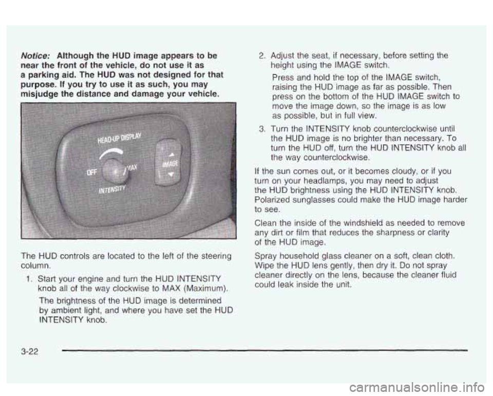
The HUD controls are located to the left of the steering
column.
1. Start your engine and turn the HUD INTENSITY
knob all
of the way clockwise to MAX (Maximum).
The brightness of the HUD image is determined
by ambient light, and where you have set the HUD
INTENSITY knob.
2. Adjust the seat, if necessary, before setting the
height using the IMAGE switch.
Press and hold the top of the IMAGE switch,
raising the HUD image as far as possible. Then
press on the bottom of the HUD IMAGE switch to
move the image down,
so the image is as low
as possible, but in full view.
3. Turn the INTENSITY knob counterclockwise until
the HUD image is no brighter than necessary. To
turn the HUD
off, turn the HUD INTENSITY knob all
the way counterclockwise.
If the sun comes out, or it becomes cloudy, or if you
turn on your headlamps, you may need to adjust
the HUD brightness using the HUD INTENSITY knob.
Polarized sunglasses could make the HUD image harder
to see.
Clean the inside of the windshield as needed to remove
any dirt or film that reduces the sharpness
or clarity
of the HUD image.
Spray household glass cleaner on a
soft, clean cloth.
Wipe the HUD lens gently, then dry it.
Do not spray
cleaner directly on the lens, because the cleaner fluid
could leak inside the unit.
3-22
Page 138 of 418
If you can’t see the HUD image when the ignition is on,
check to see
if:
0 The HUD unit is covered,
0 the HUD INTENSITY knob is adjusted correctly,
0 the HUD image is adjusted to the proper height, or
a fuse in the fuse panel may have blown. See
Fuses and Circuit Breakers on page 5-92.
If the HUD image is not clear, it could be too bright.
Move the HUD INTENSITY knob counterclockwise. You
may need to clean the windshield and HUD lens.
Your windshield is part of the HUD system. If you ever
have to have a new windshield, be sure to get one
designed for HUD.
If you don’t, the HUD image may look
blurred and out of focus.
Accessory Power Outlets
If your vehicle has a front console, the accessory power
outlet
(1 2-volt ) is located at the rear of the front
console.
If your vehicle has a floor console, the outlet is
located at the rear of the floor console. To
use the outlet, remove the protective cap which
covers it. When not using it, always cover the outlet with
the protective cap.
The accessory power outlet will only operate when the
ignition key
is in ON and for 10 minutes after turning
the ignition OFF. If you would like the accessory power
outlet to operate regardless of ignition position, and
for extended periods of time, see “Engine Compartment
Fuse
Block” under Fuses and Circuit Breakers on
page 5-92 or see your dealer for more information.
Nofice: When using an accessory power outlet,
maximum electrical load must not exceed
15 amps.
Always turn
off any electrical equipment when
not in use. Leaving electrical equipment on for
extended periods will drain your battery.
Certain electrical accessories may not be compatible
with the accessory power outlet and could result
in blown vehicle or adapter fuses.
If you experience a
problem, see your dealer for additional information
on accessory power outlets.
3-23
Page 139 of 418
Notice: Adding some electrical equipment to your
vehicle can damage
it or keep other things from
working as they should. This wouldn’t be covered by
your warranty. Check with your dealer before adding electrical equipment, and never use anything
that exceeds the amperage rating.
When adding electrical equipment, be sure to follow the
proper installation instructions included with the
equipment.
Notice: Power outlets are designed for accessory
plugs only.
Do not hang any type of accessory
or accessory bracket from the plug. Improper use of
the power outlet can cause damage not covered
by your warranty.
Ashtrays and Cigarette Lighter
Push down on the cover to reveal the front ashtray.
To clean the ashtray,
lift it out by pulling on the finger
holes on each side.
On models without a console, an ashtray is located
underneath the instrument panel.
To clean the ashtray,
lift it out by pulling up on the tabs on either side.
It snaps back into place.
To open a rear ashtray, lift the cover
Notice: Don’t put papers or other flammable
items into your ashtrays. Hot cigarettes or other
smoking materials could ignite them, causing
a damaging fire.
The cigarette lighter is located next to the storage tray.
To use a lighter, just push the center in all the way
and let
it go. When it is ready, the center will pop back
out by itself. Pull out the entire unit to use it.
Notice: Don’t hold a cigarette lighter in with your
hand while
it is heating. If you do, it won’t be able to
back away from the heating element when it’s
ready. That can make
it overheat, damaging the
lighter and the heating element.
The cigarette lighter will only operate when the ignition
key is in
ON and for 10 minutes after turning the
ignition
OFF. If you would like the lighter to operate
regardless of ignition position, and for extended periods
of time, see “Engine Compartment Fuse Block under
Fuses and Circuit Breakers on page 5-92 or see
your dealer.
3-24
Page 141 of 418

.1#t A/C (Air Conditioning): Press this button to turn
the air conditioning compressor on and off. When
A/C is
pressed, an indicator light in the button will come on
to let you know that air conditioning is activated.
If your
climate control system is
off, you may also turn it
back on in vent mode by selecting the
A/C button.
On hot days, open the windows
to let hot inside
air escape; then close them. This helps
to reduce the
time
it takes for your vehicle to cool down. It also helps
the system
to operate more efficiently.
For quick cool down on hot days, do the following:
1. Select the vent mode.
2. Select the recirculation mode.
3. Select NC.
4. Select the coolest temperature.
5. Select the highest fan speed.
Using these settings together for long periods of time
may cause the air inside
of your vehicle to become too
dry.
To prevent this from happening, after the air in
your vehicle has cooled, turn the recirculation mode
off.
The air conditioning system removes moisture from
the air,
so you may sometimes notice a small amount of
water dripping underneath your vehicle while idling or
after turning off the engine. This is normal.
Sensors
The solar sensor on your vehicle monitors
radiation and the air inside of your vehicle, the solar
then uses the
information
to maintain the selected temperature by
initiating needed adjustments
to the temperature, the fan
speed and the air delivery system. The system may
also supply cooler air to the side of the vehicle facing the
sun. The recirculation mode will also be activated, as
necessary.
Do not cover the solar sensor located in the
center of the instrument panel, near the windshield,
or the system will not work properly.
Defogging and Defrosting
There are two modes to clear fog or frost from your
windshield. Use the defog mode to clear the windows of
fog or moisture and warm the passengers. Use the
defrost mode
to remove fog or frost from the windshield
more quickly.
Press one of the available mode buttons
to select the
defog or defrost mode.
+3 (Defog): This mode directs most of the air to the
windshield and the floor outlets.
A small amount of air is
also directed to the outboard outlets (for the side
windows). When you select this mode, the system turns
off recirculation and runs the air conditioning compressor
unless the outside temperature is at or below freezing.
The recirculation mode cannot be selected while in
the defog mode.
3-26
Page 142 of 418
@ FRONT (Defrost): Pressing this button directs
most of the air to the windshield and the outboard outlets
(for the side windows), with some air directed to the
floor outlets. When you select this mode, the system
turns
off recirculation and runs the air conditioning
compressor unless the outside temperature is at
or below freezing. The recirculation mode cannot be
selected while in the FRONT defrost mode.
Rear Window Defogger
The rear window defogger uses a warming grid to
remove fog or frost from the rear window.
ISH] REAR: Press this button to turn the rear window
defogger on or
off. Be sure to clear as much snow from
the rear window as possible.
The rear window defogger will turn
off approximately
10 minutes after the button is pressed. If turned on
again, the defogger
will only run for approximately five minutes before turning
off. If you maintain
a speed
above
30 mph (48 km/h), the rear defogger will not turn
off automatically to help keep the rear glass clear.
The defogger can also be turned
off by pressing the
button again or by turning
off the engine.
if your vehicle has outside heated mirrors, the mirrors
will heat to help clear fog or frost from the surface of the
mirror when the rear window defogger button is
pressed.
Notice: Don’t use a razor blade or something else
sharp on the inside of the rear window.
If you
do, you could cut or damage the defogger and the
repairs would not be covered by your warranty.
Do not attach
a temporary vehicie iicense, tape, a
decal or anything similar to the defogger grid.
3-27