Page 1981 of 4179
TRANSAXLE ASSEMBLY
MT-49
D
E
F
G
H
I
J
K
L
MA
B
MT
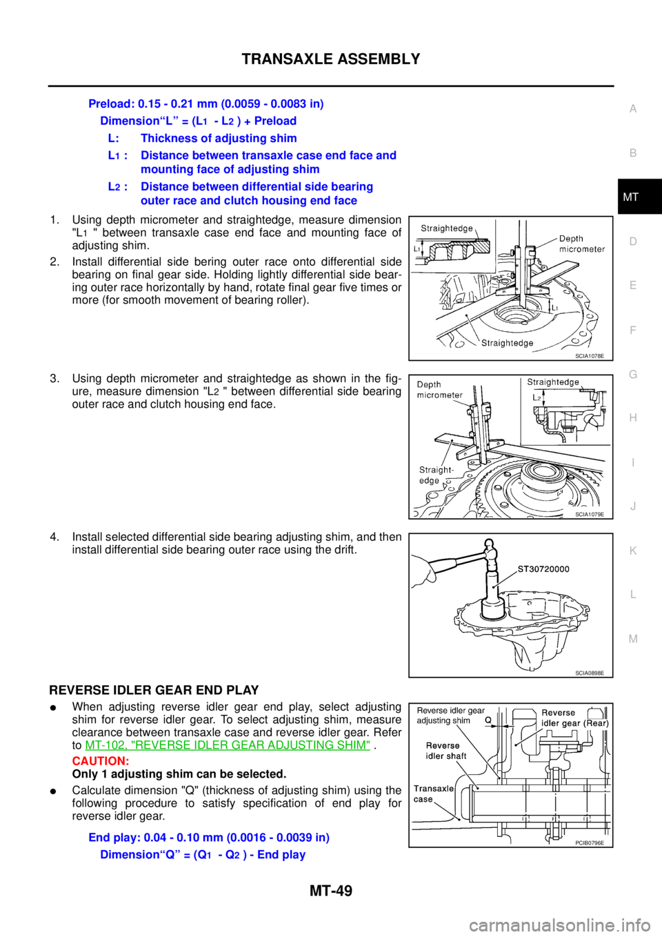
1. Using depth micrometer and straightedge, measure dimension
"L
1 " between transaxle case end face and mounting face of
adjusting shim.
2. Install differential side bering outer race onto differential side
bearing on final gear side. Holding lightly differential side bear-
ing outer race horizontally by hand, rotate final gear five times or
more (for smooth movement of bearing roller).
3. Using depth micrometer and straightedge as shown in the fig-
ure, measure dimension "L
2 " between differential side bearing
outer race and clutch housing end face.
4. Install selected differential side bearing adjusting shim, and then
install differential side bearing outer race using the drift.
REVERSE IDLER GEAR END PLAY
�When adjusting reverse idler gear end play, select adjusting
shim for reverse idler gear. To select adjusting shim, measure
clearance between transaxle case and reverse idler gear. Refer
to MT-102, "
REVERSE IDLER GEAR ADJUSTING SHIM" .
CAUTION:
Only 1 adjusting shim can be selected.
�Calculate dimension "Q" (thickness of adjusting shim) using the
following procedure to satisfy specification of end play for
reverse idler gear.Preload: 0.15 - 0.21 mm (0.0059 - 0.0083 in)
Dimension“L” = (L
1 - L2 ) + Preload
L: Thickness of adjusting shim
L
1 : Distance between transaxle case end face and
mounting face of adjusting shim
L
2 : Distance between differential side bearing
outer race and clutch housing end face
SCIA1078E
SCIA1079E
SCIA0898E
End play: 0.04 - 0.10 mm (0.0016 - 0.0039 in)
Dimension“Q” = (Q
1 - Q2 ) - End play
PCIB0796E
Page 1982 of 4179
MT-50
TRANSAXLE ASSEMBLY
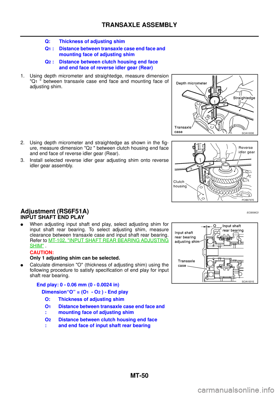
1. Using depth micrometer and straightedge, measure dimension
"Q
1 " between transaxle case end face and mounting face of
adjusting shim.
2. Using depth micrometer and straightedge as shown in the fig-
ure, measure dimension "Q
2 " between clutch housing end face
and end face of reverse idler gear (Rear).
3. Install selected reverse idler gear adjusting shim onto reverse
idler gear assembly.
Adjustment (RS6F51A)ECS008C3
INPUT SHAFT END PLAY
�When adjusting input shaft end play, select adjusting shim for
input shaft rear bearing. To select adjusting shim, measure
clearance between transaxle case and input shaft rear bearing.
Refer to MT-102, "
INPUT SHAFT REAR BEARING ADJUSTING
SHIM" .
CAUTION:
Only 1 adjusting shim can be selected.
�Calculate dimension "O" (thickness of adjusting shim) using the
following procedure to satisfy specification of end play for input
shaft rear bearing.Q: Thickness of adjusting shim
Q
1 : Distance between transaxle case end face and
mounting face of adjusting shim
Q
2 : Distance between clutch housing end face
and end face of reverse idler gear (Rear)
SCIA1003E
PCIB0797E
End play: 0 - 0.06 mm (0 - 0.0024 in)
Dimension“O” = (O
1 - O2 ) - End play
O: Thickness of adjusting shim
O
1
:Distance between transaxle case end face and
mounting face of adjusting shim
O
2
:Distance between clutch housing end face
and end face of input shaft rear bearing
SCIA1001E
Page 1983 of 4179
TRANSAXLE ASSEMBLY
MT-51
D
E
F
G
H
I
J
K
L
MA
B
MT
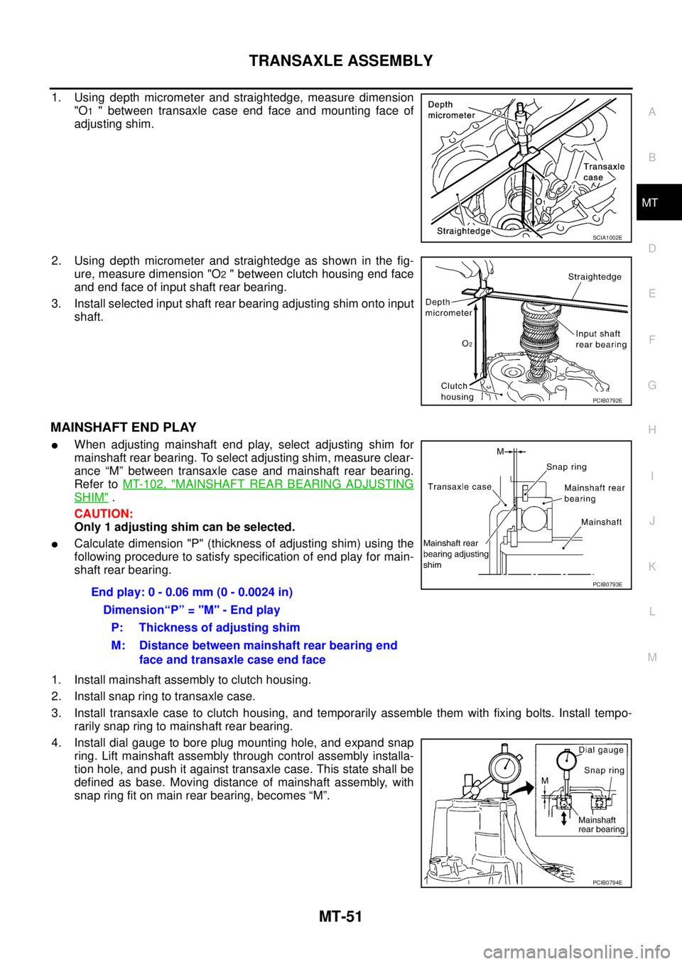
1. Using depth micrometer and straightedge, measure dimension
"O
1 " between transaxle case end face and mounting face of
adjusting shim.
2. Using depth micrometer and straightedge as shown in the fig-
ure, measure dimension "O
2 " between clutch housing end face
and end face of input shaft rear bearing.
3. Install selected input shaft rear bearing adjusting shim onto input
shaft.
MAINSHAFT END PLAY
�When adjusting mainshaft end play, select adjusting shim for
mainshaft rear bearing. To select adjusting shim, measure clear-
ance “M” between transaxle case and mainshaft rear bearing.
Refer to MT-102, "
MAINSHAFT REAR BEARING ADJUSTING
SHIM" .
CAUTION:
Only 1 adjusting shim can be selected.
�Calculate dimension "P" (thickness of adjusting shim) using the
following procedure to satisfy specification of end play for main-
shaft rear bearing.
1. Install mainshaft assembly to clutch housing.
2. Install snap ring to transaxle case.
3. Install transaxle case to clutch housing, and temporarily assemble them with fixing bolts. Install tempo-
rarily snap ring to mainshaft rear bearing.
4. Install dial gauge to bore plug mounting hole, and expand snap
ring. Lift mainshaft assembly through control assembly installa-
tion hole, and push it against transaxle case. This state shall be
defined as base. Moving distance of mainshaft assembly, with
snap ring fit on main rear bearing, becomes “M”.
SCIA1002E
PCIB0792E
End play: 0 - 0.06 mm (0 - 0.0024 in)
Dimension“P” = "M" - End play
P: Thickness of adjusting shim
M: Distance between mainshaft rear bearing end
face and transaxle case end facePCIB0793E
PCIB0794E
Page 1984 of 4179
MT-52
TRANSAXLE ASSEMBLY
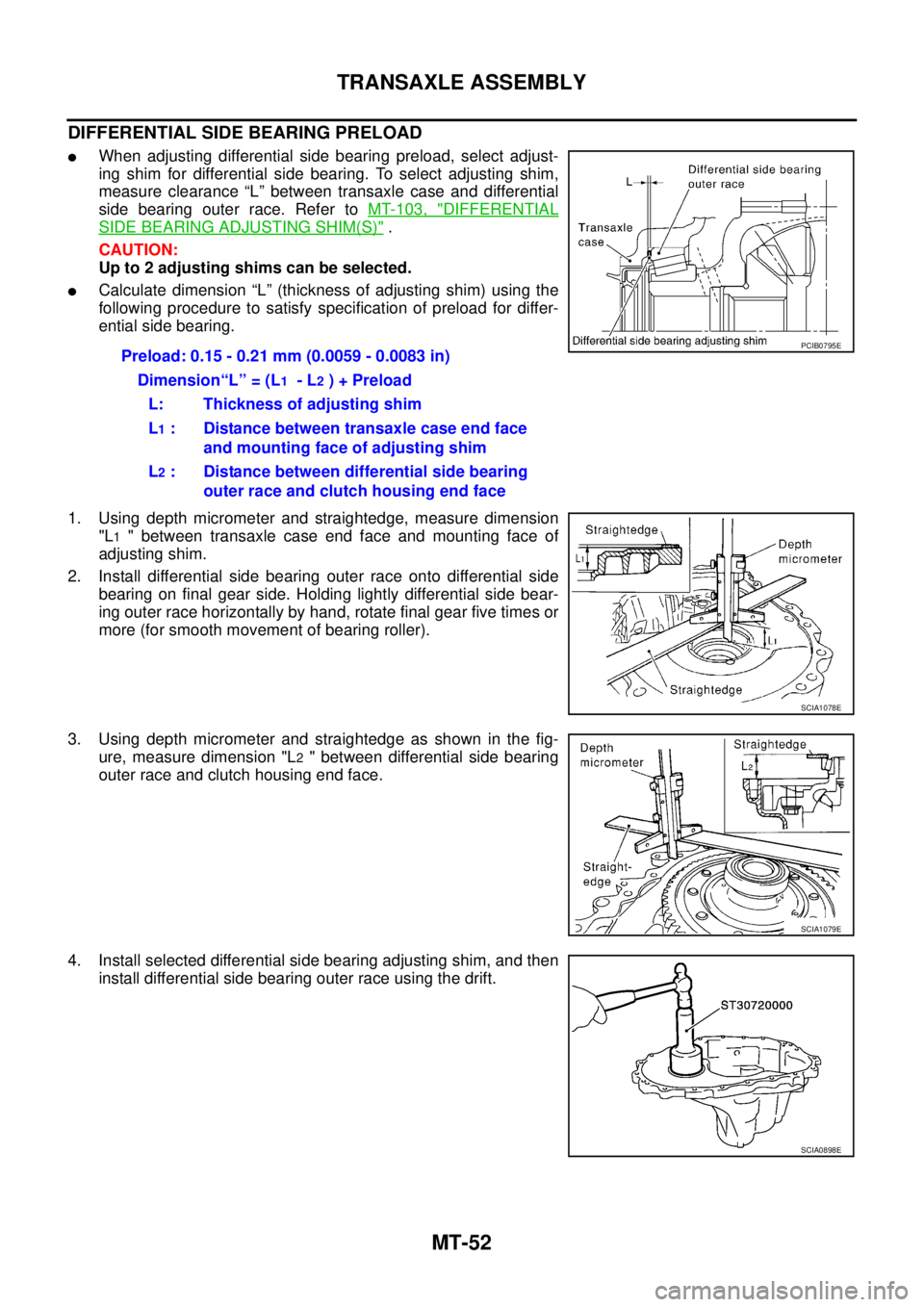
DIFFERENTIAL SIDE BEARING PRELOAD
�When adjusting differential side bearing preload, select adjust-
ing shim for differential side bearing. To select adjusting shim,
measure clearance “L” between transaxle case and differential
side bearing outer race. Refer to MT-103, "
DIFFERENTIAL
SIDE BEARING ADJUSTING SHIM(S)" .
CAUTION:
Up to 2 adjusting shims can be selected.
�Calculate dimension “L” (thickness of adjusting shim) using the
following procedure to satisfy specification of preload for differ-
ential side bearing.
1. Using depth micrometer and straightedge, measure dimension
"L
1 " between transaxle case end face and mounting face of
adjusting shim.
2. Install differential side bearing outer race onto differential side
bearing on final gear side. Holding lightly differential side bear-
ing outer race horizontally by hand, rotate final gear five times or
more (for smooth movement of bearing roller).
3. Using depth micrometer and straightedge as shown in the fig-
ure, measure dimension "L
2 " between differential side bearing
outer race and clutch housing end face.
4. Install selected differential side bearing adjusting shim, and then
install differential side bearing outer race using the drift.Preload: 0.15 - 0.21 mm (0.0059 - 0.0083 in)
Dimension“L” = (L
1 - L2 ) + Preload
L: Thickness of adjusting shim
L
1 : Distance between transaxle case end face
and mounting face of adjusting shim
L
2 : Distance between differential side bearing
outer race and clutch housing end face
PCIB0795E
SCIA1078E
SCIA1079E
SCIA0898E
Page 1985 of 4179
TRANSAXLE ASSEMBLY
MT-53
D
E
F
G
H
I
J
K
L
MA
B
MT
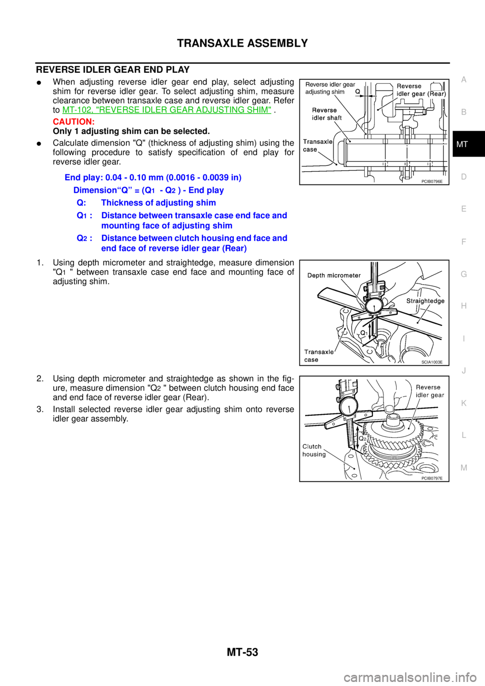
REVERSE IDLER GEAR END PLAY
�When adjusting reverse idler gear end play, select adjusting
shim for reverse idler gear. To select adjusting shim, measure
clearance between transaxle case and reverse idler gear. Refer
to MT-102, "
REVERSE IDLER GEAR ADJUSTING SHIM" .
CAUTION:
Only 1 adjusting shim can be selected.
�Calculate dimension "Q" (thickness of adjusting shim) using the
following procedure to satisfy specification of end play for
reverse idler gear.
1. Using depth micrometer and straightedge, measure dimension
"Q
1 " between transaxle case end face and mounting face of
adjusting shim.
2. Using depth micrometer and straightedge as shown in the fig-
ure, measure dimension "Q
2 " between clutch housing end face
and end face of reverse idler gear (Rear).
3. Install selected reverse idler gear adjusting shim onto reverse
idler gear assembly.End play: 0.04 - 0.10 mm (0.0016 - 0.0039 in)
Dimension“Q” = (Q
1 - Q2 ) - End play
Q: Thickness of adjusting shim
Q
1 : Distance between transaxle case end face and
mounting face of adjusting shim
Q
2 : Distance between clutch housing end face and
end face of reverse idler gear (Rear)
PCIB0796E
SCIA1003E
PCIB0797E
Page 2003 of 4179
MAINSHAFT AND GEARS
MT-71
D
E
F
G
H
I
J
K
L
MA
B
MT
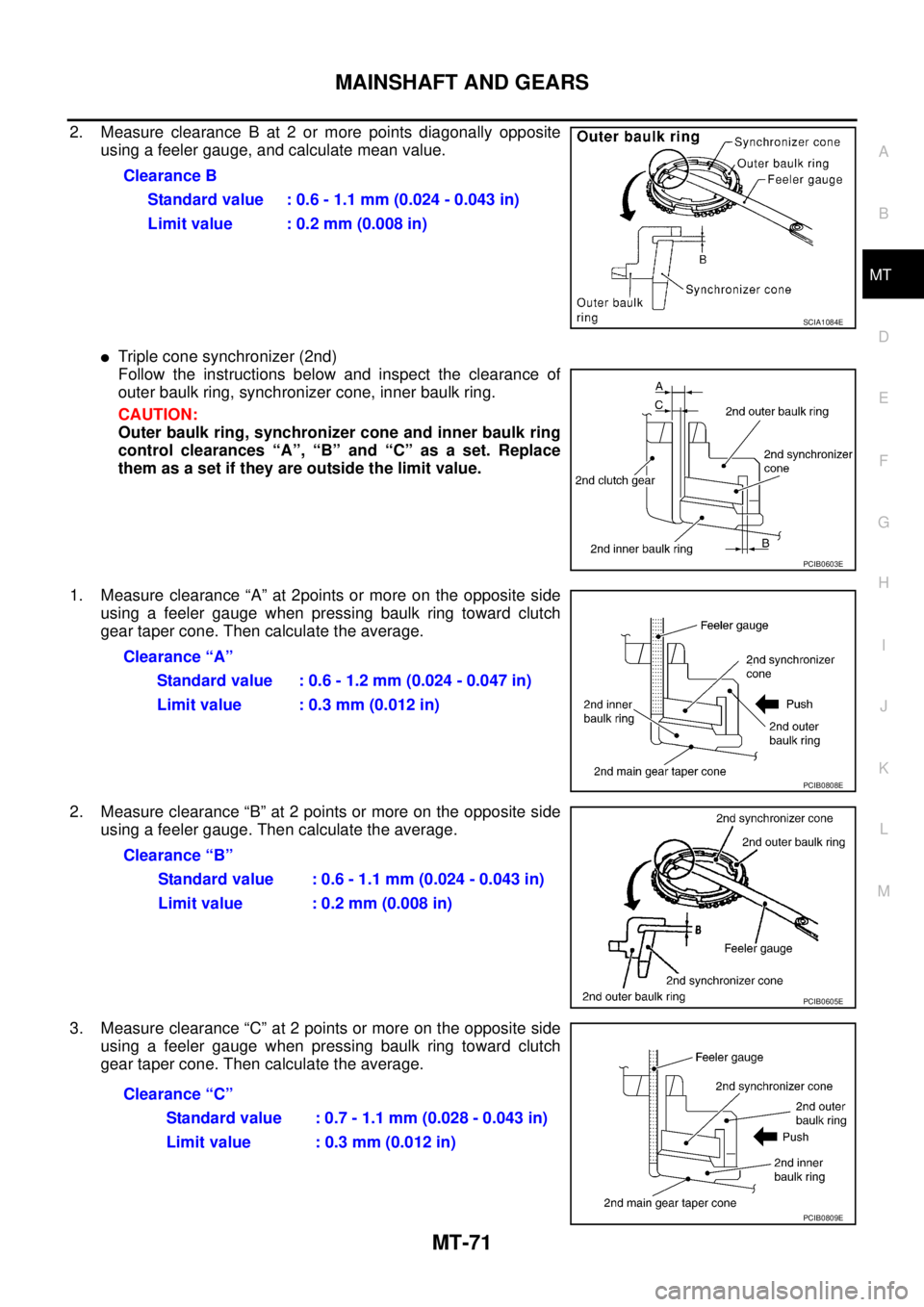
2. Measure clearance B at 2 or more points diagonally opposite
using a feeler gauge, and calculate mean value.
�Triple cone synchronizer (2nd)
Follow the instructions below and inspect the clearance of
outer baulk ring, synchronizer cone, inner baulk ring.
CAUTION:
Outer baulk ring, synchronizer cone and inner baulk ring
control clearances “A”, “B” and “C” as a set. Replace
them as a set if they are outside the limit value.
1. Measure clearance “A” at 2points or more on the opposite side
using a feeler gauge when pressing baulk ring toward clutch
gear taper cone. Then calculate the average.
2. Measure clearance “B” at 2 points or more on the opposite side
using a feeler gauge. Then calculate the average.
3. Measure clearance “C” at 2 points or more on the opposite side
using a feeler gauge when pressing baulk ring toward clutch
gear taper cone. Then calculate the average.Clearance B
Standard value : 0.6 - 1.1 mm (0.024 - 0.043 in)
Limit value : 0.2 mm (0.008 in)
SCIA1084E
PCIB0603E
Clearance “A”
Standard value : 0.6 - 1.2 mm (0.024 - 0.047 in)
Limit value : 0.3 mm (0.012 in)
PCIB0808E
Clearance “B”
Standard value : 0.6 - 1.1 mm (0.024 - 0.043 in)
Limit value : 0.2 mm (0.008 in)
PCIB0605E
Clearance “C”
Standard value : 0.7 - 1.1 mm (0.028 - 0.043 in)
Limit value : 0.3 mm (0.012 in)
PCIB0809E
Page 2011 of 4179
MAINSHAFT AND GEARS
MT-79
D
E
F
G
H
I
J
K
L
MA
B
MT
1. Measure clearance “A” at 2 points or more on the opposite side
using a feeler gauge when pressing baulk ring toward clutch
gear taper cone. Then calculate the average.
2. Measure clearance “B” at 2 points or more on the opposite side
using a feeler gauge. Then calculate the average.
3. Measure clearance “C” at 2 points or more on the opposite side
using a feeler gauge when pressing baulk ring toward clutch
gear taper cone. Then calculate the average.
Bearing
Check items below. If necessary, replace them with new ones.
�Damage and rough rotation of bearingClearance “A”
Standard value : 0.6 - 1.2 mm (0.024- 0.047)
Limit value : 0.3 mm (0.012 in)
PCIB0808E
Clearance “B”
Standard value : 0.6 - 1.1 mm (0.024 - 0.043)
Limit value : 0.2 mm (0.008 in)
PCIB0605E
Clearance “C”
Standard value : 0.7 - 1.1 mm (0.028 - 0.043 in)
Limit value : 0.3 mm (0.012 in)
PCIB0809E
MTF0041D
Page 2021 of 4179
FINAL DRIVE
MT-89
D
E
F
G
H
I
J
K
L
MA
B
MT
FINAL DRIVEPFP:38411
Assembly and Disassembly (RS5F51A)ECS008CA
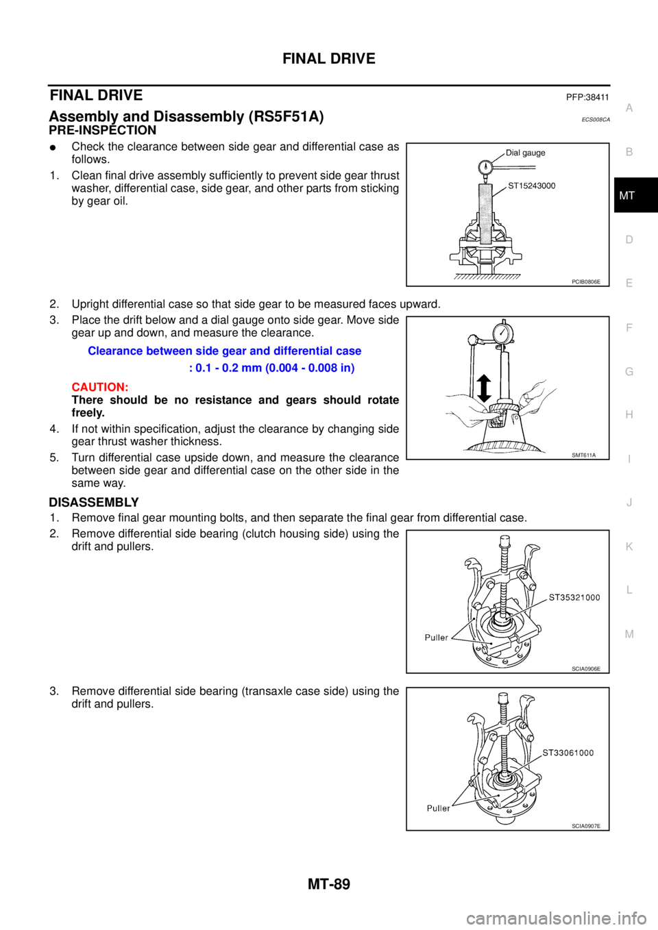
PRE-INSPECTION
�Check the clearance between side gear and differential case as
follows.
1. Clean final drive assembly sufficiently to prevent side gear thrust
washer, differential case, side gear, and other parts from sticking
by gear oil.
2. Upright differential case so that side gear to be measured faces upward.
3. Place the drift below and a dial gauge onto side gear. Move side
gear up and down, and measure the clearance.
CAUTION:
There should be no resistance and gears should rotate
freely.
4. If not within specification, adjust the clearance by changing side
gear thrust washer thickness.
5. Turn differential case upside down, and measure the clearance
between side gear and differential case on the other side in the
same way.
DISASSEMBLY
1. Remove final gear mounting bolts, and then separate the final gear from differential case.
2. Remove differential side bearing (clutch housing side) using the
drift and pullers.
3. Remove differential side bearing (transaxle case side) using the
drift and pullers.
PCIB0806E
Clearance between side gear and differential case
: 0.1 - 0.2 mm (0.004 - 0.008 in)
SMT611A
SCIA0906E
SCIA0907E