Page 3733 of 4179
WARNING CHIME
DI-55
C
D
E
F
G
H
I
J
L
MA
B
DI
Wiring Diagram — CHIME —/LHD ModelsEKS002XJ
TKWA1626E
Page 3734 of 4179
DI-56
WARNING CHIME
Wiring Diagram — CHIME —/RHD ModelsEKS00EKI
TKWA1628E
Page 3739 of 4179
CLOCK
DI-61
C
D
E
F
G
H
I
J
L
MA
B
DI
CLOCKPFP:25820
Wiring Diagram — CLOCK —EKS002I5
TKWA1630E
Page 3741 of 4179

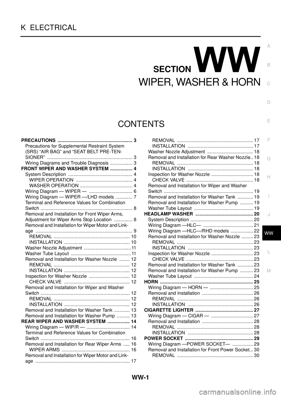
WW-1
WIPER, WASHER & HORN
K ELECTRICAL
CONTENTS
C
D
E
F
G
H
I
J
L
M
SECTION
A
B
WW
WIPER, WASHER & HORN
PRECAUTIONS .......................................................... 3
Precautions for Supplemental Restraint System
(SRS) “AIR BAG” and “SEAT BELT PRE-TEN-
SIONER” .................................................................. 3
Wiring Diagrams and Trouble Diagnosis .................. 3
FRONT WIPER AND WASHER SYSTEM .................. 4
System Description .................................................. 4
WIPER OPERATION ............................................ 4
WASHER OPERATION ......................................... 4
Wiring Diagram — WIPER — .................................. 6
Wiring Diagram — WIPER —/LHD models .............. 7
Terminal and Reference Values for Combination
Switch ....................................................................... 8
Removal and Installation for Front Wiper Arms,
Adjustment for Wiper Arms Stop Location ............... 8
Removal and Installation for Wiper Motor and Link-
age ........................................................................... 9
REMOVAL ........................................................... 10
INSTALLATION ................................................... 10
Washer Nozzle Adjustment ..................................... 11
Washer Tube Layout ............................................... 11
Removal and Installation for Washer Nozzle ......... 12
REMOVAL ........................................................... 12
INSTALLATION ................................................... 12
Inspection for Washer Nozzle ................................ 12
CHECK VALVE ................................................... 12
Removal and Installation for Wiper and Washer
Switch ..................................................................... 12
REMOVAL ........................................................... 12
INSTALLATION ................................................... 12
Removal and Installation for Washer Tank ............. 13
Removal and Installation for Washer Pump ........... 13
REAR WIPER AND WASHER SYSTEM .................. 14
Wiring Diagram — WIP/R — .................................. 14
Terminal and Reference Values for Combination
Switch ..................................................................... 16
Removal and Installation for Rear Wiper Arms ...... 16
WIPER ARMS ..................................................... 16
Removal and Installation for Wiper Motor and Link-
age ......................................................................... 17REMOVAL ........................................................... 17
INSTALLATION ................................................... 17
Washer Nozzle Adjustment .................................... 18
Removal and Installation for Rear Washer Nozzle ... 18
REMOVAL ........................................................... 18
INSTALLATION ................................................... 18
Inspection for Washer Nozzle ................................. 18
CHECK VALVE .................................................... 18
Removal and Installation for Wiper and Washer
Switch ..................................................................... 19
Removal and Installation for Washer Tank ............. 19
Removal and Installation for Washer Pump ........... 19
Washer Tube Layout .............................................. 19
HEADLAMP WASHER ............................................. 20
System Description ................................................. 20
Wiring Diagram —HLC— ....................................... 21
Wiring Diagram —HLC—/RHD models .................. 22
Removal and Installation for Washer Nozzle .......... 23
REMOVAL ........................................................... 23
INSTALLATION ................................................... 23
Inspection for Washer Nozzle ................................. 23
CHECK VALVE .................................................... 23
Removal and Installation for Washer Tank ............. 23
Removal and Installation for Washer Pump ........... 23
Washer Tube Layout .............................................. 24
HORN ........................................................................ 25
Wiring Diagram — HORN — .................................. 25
Removal and Installation ........................................ 26
REMOVAL ........................................................... 26
INSTALLATION ................................................... 26
CIGARETTE LIGHTER ............................................. 27
Wiring Diagram — CIGAR — ................................. 27
Removal and Installation ........................................ 28
REMOVAL ........................................................... 28
INSTALLATION ................................................... 28
POWER SOCKET ..................................................... 29
Wiring Diagram —POWER SOCKET— ................. 29
Removal and Installation for Front Power Socket ... 30
REMOVAL ........................................................... 30
Page 3743 of 4179

PRECAUTIONS
WW-3
C
D
E
F
G
H
I
J
L
MA
B
WW
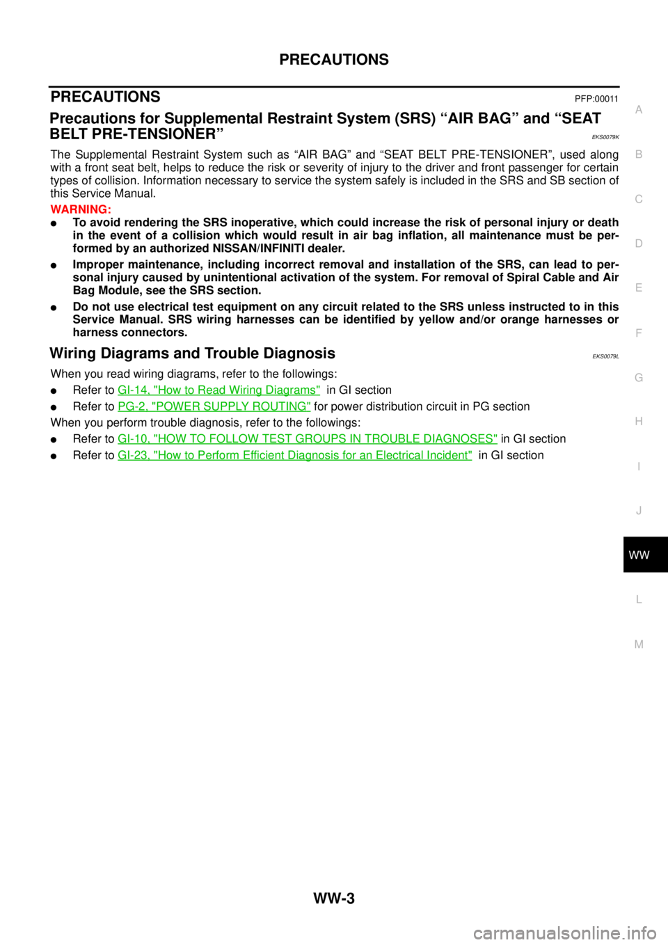
PRECAUTIONS PFP:00011
Precautions for Supplemental Restraint System (SRS) “AIR BAG” and “SEAT
BELT PRE-TENSIONER”
EKS0079K
The Supplemental Restraint System such as “AIR BAG” and “SEAT BELT PRE-TENSIONER”, used along
with a front seat belt, helps to reduce the risk or severity of injury to the driver and front passenger for certain
types of collision. Information necessary to service the system safely is included in the SRS and SB section of
this Service Manual.
WARNING:
�To avoid rendering the SRS inoperative, which could increase the risk of personal injury or death
in the event of a collision which would result in air bag inflation, all maintenance must be per-
formed by an authorized NISSAN/INFINITI dealer.
�Improper maintenance, including incorrect removal and installation of the SRS, can lead to per-
sonal injury caused by unintentional activation of the system. For removal of Spiral Cable and Air
Bag Module, see the SRS section.
�Do not use electrical test equipment on any circuit related to the SRS unless instructed to in this
Service Manual. SRS wiring harnesses can be identified by yellow and/or orange harnesses or
harness connectors.
Wiring Diagrams and Trouble Diagnosis EKS0079L
When you read wiring diagrams, refer to the followings:
�Refer to GI-14, "How to Read Wiring Diagrams" in GI section
�Refer to PG-2, "POWER SUPPLY ROUTING" for power distribution circuit in PG section
When you perform trouble diagnosis, refer to the followings:
�Refer to GI-10, "HOW TO FOLLOW TEST GROUPS IN TROUBLE DIAGNOSES" in GI section
�Refer to GI-23, "How to Perform Efficient Diagnosis for an Electrical Incident" in GI section
Page 3746 of 4179
WW-6
FRONT WIPER AND WASHER SYSTEM
Wiring Diagram — WIPER —EKS0032O
TKWA1554E
Page 3747 of 4179
FRONT WIPER AND WASHER SYSTEM
WW-7
C
D
E
F
G
H
I
J
L
MA
B
WW
Wiring Diagram — WIPER —/LHD modelsEKS00ES7
TKWA1555E
Page 3754 of 4179
WW-14
REAR WIPER AND WASHER SYSTEM
REAR WIPER AND WASHER SYSTEMPFP:28710
Wiring Diagram — WIP/R —EKS0032Z
TKWA1556E