Page 3688 of 4179
DI-10
COMBINATION METERS
TYPE 5
System diagram
Input/output signal chart
T: Transmit R: Receive
PKIA6460E
Signals ECM TCMESP/TCS/
ABS control
unitSte ering
angle sensor4WD control
unitCombination
meter
Stop lamp switch signalRT
TR
P·N range signal R T
A/T position indicator lamp signal T R R
O/D OFF indicator signal T R
Overdrive control switch signal R T
Engine speed signal T R R R
Engine coolant temperature signal TR
A/C compressor feedback signal TR
Vehicle speed signalTRR
RT
ABS warning lamp signal T R
Brake warning lamp signal T R
SLIP indicator lamp signal T R
ESP OFF indicator lamp signal T R
4WD warning lamp signalTR
4WD mode indicator lamp signalTR
Parking brake switch signalRT
MI signal TR
Page 3692 of 4179
DI-14
COMBINATION METERS
Wiring Diagram — METER —/LHD ModelsEKS00EH5
TKWA1606E
Page 3695 of 4179
COMBINATION METERS
DI-17
C
D
E
F
G
H
I
J
L
MA
B
DI
Wiring Diagram — METER —/RHD ModelsEKS00EHM
TKWA1609E
Page 3712 of 4179
DI-34
WARNING LAMPS
Wiring Diagram — WARN —/LHD ModelsEKS002HH
TKWA1612E
Page 3720 of 4179
DI-42
WARNING LAMPS
Wiring Diagram — WARN —/RHD ModelsEKS0031U
TKWA1618E
Page 3728 of 4179
DI-50
WARNING LAMPS
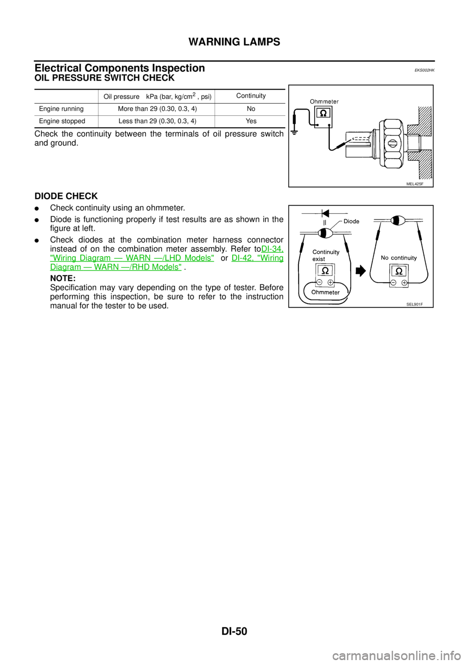
Electrical Components InspectionEKS002HK
OIL PRESSURE SWITCH CHECK
Check the continuity between the terminals of oil pressure switch
and ground.
DIODE CHECK
�Check continuity using an ohmmeter.
�Diode is functioning properly if test results are as shown in the
figure at left.
�Check diodes at the combination meter harness connector
instead of on the combination meter assembly. Refer toDI-34,
"Wiring Diagram — WARN —/LHD Models" or DI-42, "Wiring
Diagram — WARN —/RHD Models" .
NOTE:
Specification may vary depending on the type of tester. Before
performing this inspection, be sure to refer to the instruction
manual for the tester to be used.
Oil pressure kPa (bar, kg/cm2 , psi)Continuity
Engine running More than 29 (0.30, 0.3, 4) No
Engine stopped Less than 29 (0.30, 0.3, 4) Yes
MEL425F
SEL901F
Page 3729 of 4179
A/T INDICATOR
DI-51
C
D
E
F
G
H
I
J
L
MA
B
DI
A/T INDICATORPFP:24814
Wiring Diagram — AT/IND —/LHD ModelsEKS002HL
TKWA1624E
Page 3730 of 4179
DI-52
A/T INDICATOR
Wiring Diagram — AT/IND —/RHD ModelsEKS00EKF
TKWA1625E