2003 NISSAN X-TRAIL oil change
[x] Cancel search: oil changePage 3607 of 4179

SERVICE DATA AND SPECIFICATIONS (SDS)
MA-47
C
D
E
F
G
H
I
J
K
MA
B
MA
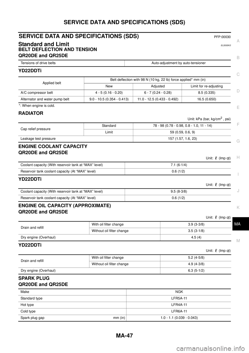
SERVICE DATA AND SPECIFICATIONS (SDS)PFP:00030
Standard and LimitELS000K3
BELT DEFLECTION AND TENSION
QR20DE and QR25DE
YD22DDTi
*: When engine is cold.
RADIATOR
Unit: kPa (bar, kg/cm2 , psi)
ENGINE COOLANT CAPACITY
QR20DE and QR25DE
Unit: (lmp qt)
YD22DDTi
Unit: (lmp qt)
ENGINE OIL CAPACITY (APPROXIMATE)
QR20DE and QR25DE
Unit: (lmp qt)
YD22DDTi
Unit: (lmp qt)
SPARK PLUG
QR20DE and QR25DE
Tensions of drive belts Auto-adjustment by auto-tensioner
Applied beltBelt deflection with 98 N (10 kg, 22 lb) force applied* mm (in)
New Adjusted Limit for re-adjusting
A/C compressor belt 4 - 5 (0.16 - 0.20) 6 - 7 (0.24 - 0.28) 8.5 (0.335)
Alternator and water pump belt 9.0 - 10.5 (0.354 - 0.413) 11.0 - 12.5 (0.433 - 0.492) 16.5 (0.650)
Cap relief pressureStandard 78 - 98 (0.78 - 0.98, 0.8 - 1.0, 11 - 14)
Limit 59 (0.59, 0.6, 9)
Leakage test pressure 157 (1.57, 1.6, 23)
Coolant capacity (With reservoir tank at “MAX” level) 7.1 (6-1/4)
Reservoir tank coolant capacity (At “MAX” level) 0.6 (1/2)
Coolant capacity (With reservoir tank at “MAX” level) 9.5 (8-3/8)
Reservoir tank coolant capacity (At “MAX” level) 0.6 (1/2)
Drain and refill With oil filter change 3.9 (3-3/8)
Without oil filter change 3.5 (3-1/8)
Dry engine (Overhaul)4.5 (4)
Drain and refill With oil filter change 5.2 (4-5/8)
Without oil filter change 4.9 (4-3/8)
Dry engine (Overhaul)6.3 (5-1/2)
MakeNGK
Standard typeLFR5A-11
Hot typeLFR4A-11
Cold typeLFR6A-11
Spark plug gap mm (in) 1.0 - 1.1 (0.039 - 0.043)
Page 3679 of 4179

DI-1
DRIVER INFORMATION SYSTEM
K ELECTRICAL
CONTENTS
C
D
E
F
G
H
I
J
L
M
SECTION
A
B
DI
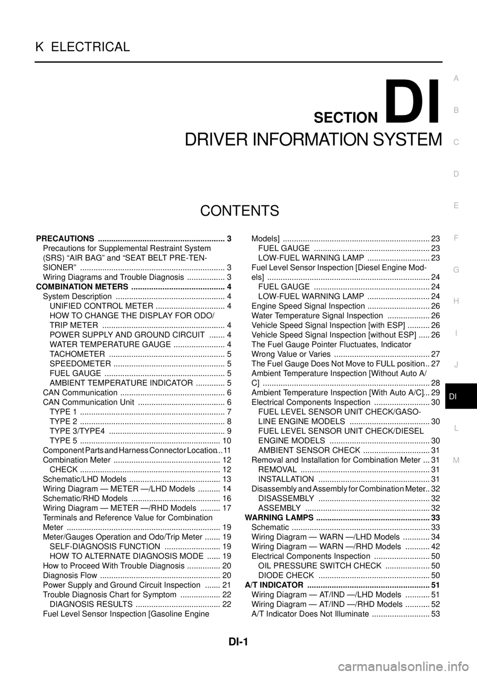
DRIVER INFORMATION SYSTEM
PRECAUTIONS .......................................................... 3
Precautions for Supplemental Restraint System
(SRS) “AIR BAG” and “SEAT BELT PRE-TEN-
SIONER” .................................................................. 3
Wiring Diagrams and Trouble Diagnosis .................. 3
COMBINATION METERS ........................................... 4
System Description .................................................. 4
UNIFIED CONTROL METER ................................ 4
HOW TO CHANGE THE DISPLAY FOR ODO/
TRIP METER ........................................................ 4
POWER SUPPLY AND GROUND CIRCUIT ........ 4
WATER TEMPERATURE GAUGE ........................ 4
TACHOMETER ..................................................... 5
SPEEDOMETER ................................................... 5
FUEL GAUGE ....................................................... 5
AMBIENT TEMPERATURE INDICATOR .............. 5
CAN Communication ................................................ 6
CAN Communication Unit ........................................ 6
TYPE 1 .................................................................. 7
TYPE 2 .................................................................. 8
TYPE 3/TYPE4 ..................................................... 9
TYPE 5 ................................................................ 10
Component Parts and Harness Connector Location .... 11
Combination Meter ................................................. 12
CHECK ................................................................ 12
Schematic/LHD Models .......................................... 13
Wiring Diagram — METER —/LHD Models ........... 14
Schematic/RHD Models ......................................... 16
Wiring Diagram — METER —/RHD Models .......... 17
Terminals and Reference Value for Combination
Meter ...................................................................... 19
Meter/Gauges Operation and Odo/Trip Meter ........ 19
SELF-DIAGNOSIS FUNCTION .......................... 19
HOW TO ALTERNATE DIAGNOSIS MODE ....... 19
How to Proceed With Trouble Diagnosis ................ 20
Diagnosis Flow ....................................................... 20
Power Supply and Ground Circuit Inspection ........ 21
Trouble Diagnosis Chart for Symptom ................... 22
DIAGNOSIS RESULTS ....................................... 22
Fuel Level Sensor Inspection [Gasoline Engine Models] ................................................................... 23
FUEL GAUGE ..................................................... 23
LOW-FUEL WARNING LAMP ............................. 23
Fuel Level Sensor Inspection [Diesel Engine Mod-
els] .......................................................................... 24
FUEL GAUGE ..................................................... 24
LOW-FUEL WARNING LAMP ............................. 24
Engine Speed Signal Inspection ............................. 26
Water Temperature Signal Inspection .................... 26
Vehicle Speed Signal Inspection [with ESP] ........... 26
Vehicle Speed Signal Inspection [without ESP] ...... 26
The Fuel Gauge Pointer Fluctuates, Indicator
Wrong Value or Varies ............................................ 27
The Fuel Gauge Does Not Move to FULL position ... 27
Ambient Temperature Inspection [Without Auto A/
C] ............................................................................ 28
Ambient Temperature Inspection [With Auto A/C] ... 29
Electrical Components Inspection .......................... 30
FUEL LEVEL SENSOR UNIT CHECK/GASO-
LINE ENGINE MODELS ..................................... 30
FUEL LEVEL SENSOR UNIT CHECK/DIESEL
ENGINE MODELS .............................................. 30
AMBIENT SENSOR CHECK ............................... 31
Removal and Installation for Combination Meter .... 31
REMOVAL ........................................................... 31
INSTALLATION ................................................... 31
Disassembly and Assembly for Combination Meter ... 32
DISASSEMBLY ................................................... 32
ASSEMBLY ......................................................... 32
WARNING LAMPS .................................................... 33
Schematic ............................................................... 33
Wiring Diagram — WARN —/LHD Models ............. 34
Wiring Diagram — WARN —/RHD Models ............ 42
Electrical Components Inspection .......................... 50
OIL PRESSURE SWITCH CHECK ..................... 50
DIODE CHECK ................................................... 50
A/T INDICATOR ........................................................ 51
Wiring Diagram — AT/IND —/LHD Models ............ 51
Wiring Diagram — AT/IND —/RHD Models ............ 52
A/T Indicator Does Not Illuminate ........................... 53
Page 4173 of 4179

IDX-3
A
C
D
E
F
G
H
I
J
K
L B
IDX
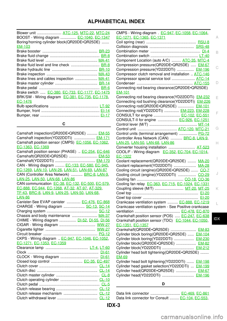
ALPHABETICAL INDEX
Blower unit ....................... ATC-125, MTC-22, MTC-24
BOOST - Wiring diagram ............... EC-1040, EC-1347
Boring/horning cylinder block(QR20DEQR25DE) .......
EM-103
Brake booster .................................................... BR-23
Brake fluid change ............................................... BR-8
Brake fluid level ................................................. MA-41
Brake fluid level and line check ........................... BR-8
Brake hydraulic line ........................................... BR-10
Brake inspection ................................................ MA-43
Brake lines and cables inspection ..................... MA-41
Brake master cylinder ........................................ BR-14
Brake pedal ......................................................... BR-6
Brake switch ..... EC-380, EC-733, EC-1177, EC-1475
BRK/SW - Wiring diagram EC-381, EC-735, EC-1178,
EC-1476
Bulb specifications .............................................. LT-92
Bumper, front ....................................................... EI-14
Bumper, rear ........................................................ EI-17
C
Camshaft inspection(QR20DEQR25DE) .......... EM-55
Camshaft inspection(YD22DDTi) .................... EM-171
Camshaft position sensor (CMPS) EC-1056, EC-1062,
EC-1363
, EC-1369
Camshaft position sensor (PHASE) .. EC-254, EC-646
Camshaft(QR20DEQR25DE) ........................... EM-53
Camshaft(YD22DDTi) ...................................... EM-170
CAN - Wiring diagram ......... EC-133, EC-580, EC-945,
EC-1269
, LAN-10, LAN-26, LAN-51, LAN-69, LAN-87
CAN (Controller Area Network) ........... BRC-8, LAN-9,
LAN-25
, LAN-50, LAN-68, LAN-86
CAN communication EC-38, EC-132, EC-500, EC-579,
EC-888
, EC-944, EC-1268, AT-32, AT-97, AT-329,
TF-43
, BRC-8, LAN-9, LAN-25, LAN-50, LAN-68,
LAN-86
Canister-See EVAP canister ............. EC-476, EC-868
CHARGE - Wiring diagram .................... SC-13, SC-14
Charging system ................................................ SC-12
Chassis and body maintenance ........................ MA-37
CHIME - Wiring diagram ................ DI-52, DI-55, DI-56
CIGAR - Wiring diagram .................................. WW-27
Cigarette lighter ............................................... WW-27
Circuit breaker ................................................... PG-12
CKPS - Wiring diagram .. EC-947, EC-1046, EC-1052,
EC-1271
, EC-1353, EC-1359
Clearance lamp ........................................ LT-4, LT-60
Clock ................................................................... DI-61
CLOCK - Wiring diagram .................................... DI-61
Closed loop control .............................. EC-35, EC-497
Clutch cover ....................................................... CL-14
Clutch disc ......................................................... CL-14
Clutch master cylinder ......................................... CL-8
Clutch operating cylinder ................................... CL-10
Clutch pedal ......................................................... CL-5
Clutch release bearing ....................................... CL-12
Clutch release mechanism ................................ CL-12
Clutch withdrawal lever ...................................... CL-12
CMPS - Wiring diagram . EC-947, EC-1058, EC-1064,
EC-1271
, EC-1365, EC-1371
Coil spring (rear) ............................................... RSU-8
Collision diagnosis .......................................... SRS-48
Combination meter ............................................... DI-4
Combination switch ............................................. LT-40
Component Location (auto A/C) ......... ATC-35, MTC-4
Compression pressure(QR20DEQR25DE) ..... EM-67
Compression pressure(YD22DDTi) ................ EM-196
Compressor clutch removal and installation .. ATC-146
Compressor special service tool ...................... ATC-14
Condenser ..................................................... ATC-155
Connecting rod bearing clearance(QR20DEQR25DE)
EM-101
Connecting rod bearing clearance(YD22DDTi) EM-232
Connecting rod bushing clearance(YD22DDTi) EM-226
Connecting rod(QR20DEQR25DE) ............... EM-101
Connecting rod(YD22DDTi) .............. EM-223, EM-228
CONSULT for engine ......................... EC-102, EC-551
CONSULT-II for engine ................... EC-926, EC-1251
Control lever (M/T) ............................................. MT-14
Control unit ..................................... ATC-120, MTC-21
Control units (terminal arrangement) ................. PG-72
Controller Area Network (CAN) ........... BRC-8, LAN-9,
LAN-25
, LAN-50, LAN-68, LAN-86
Converter housing installation ......................... AT-523
COOL/F - Wiring diagram EC-352, EC-704, EC-1014,
EC-1322
Coolant replacement(QR20DEQR25DE) ........ MA-20
Coolant replacement(YD22DDTi) ..................... MA-28
Cooling circuit (engine)(QR20DEQR25DE) ....... CO-7
Cooling circuit (engine)(YD22DDTi) ................. CO-29
Cooling fan ............................................ CO-18, CO-36
Cooling fan relay EC-363, EC-715, EC-1024, EC-1331
Coupling sleeve (M/T) ........................... MT-20, MT-25
Cowl top .............................................................. EI-20
Cowl top cover .................................................... EI-20
Crankcase ventilation system .......... EC-888, EC-1219
Crankcase ventilation system - See Positive crankcase
ventilation ........................................... EC-478
, EC-870
Crankshaft position sensor (POS) ..... EC-247, EC-638
Crankshaft position sensor (TDC) EC-1044, EC-1050,
EC-1351
, EC-1357
Crankshaft(QR20DEQR25DE) ........................ EM-83
Cylinder block boring(QR20DEQR25DE) ...... EM-104
Cylinder block boring(YD22DDTi) ................... EM-230
Cylinder block(QR20DEQR25DE) ................... EM-82
Cylinder block(YD22DDTi) .............................. EM-212
Cylinder head bolt tightening(QR20DEQR25DE) ........
EM-69
Cylinder head bolt tightening(YD22DDTi) ....... EM-198
Cylinder head gasket selection(YD22DDTi) ... EM-199
Cylinder head(QR20DEQR25DE) ................... EM-67
Cylinder head(YD22DDTi) .............................. EM-196
D
Data link connector ............................ EC-469
, EC-861
Data link connector for Consult ......... EC-104, EC-553,