Page 3954 of 4179
AV-64
NAVIGATION SYSTEM
TKWA1604E
Page 3955 of 4179
NAVIGATION SYSTEM
AV-65
C
D
E
F
G
H
I
J
L
MA
B
AV
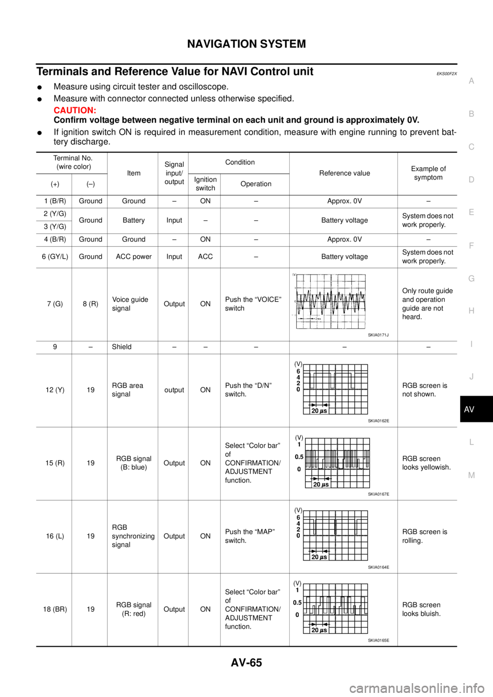
Terminals and Reference Value for NAVI Control unitEKS00F2X
�Measure using circuit tester and oscilloscope.
�Measure with connector connected unless otherwise specified.
CAUTION:
Confirm voltage between negative terminal on each unit and ground is approximately 0V.
�If ignition switch ON is required in measurement condition, measure with engine running to prevent bat-
tery discharge.
Terminal No.
(wire color)
ItemSignal
input/
outputCondition
Reference valueExample of
symptom
(+) (–)Ignition
switchOperation
1 (B/R) Ground Ground – ON – Approx. 0V –
2 (Y/G)
Ground Battery Input – – Battery voltageSystem does not
work properly.
3 (Y/G)
4 (B/R) Ground Ground – ON – Approx. 0V –
6 (GY/L) Ground ACC power Input ACC – Battery voltageSystem does not
work properly.
7 (G) 8 (R)Voice guide
signalOutput ONPush the “VOICE”
switchOnly route guide
and operation
guide are not
heard.
9 – Shield – – – – –
12 (Y) 19RGB area
signaloutput ONPush the “D/N”
switch.RGB screen is
not shown.
15 (R) 19RGB signal
(B: blue)Output ONSelect “Color bar”
of
CONFIRMATION/
ADJUSTMENT
function.RGB screen
looks yellowish.
16 (L) 19RGB
synchronizing
signalOutput ONPush the “MAP”
switch.RGB screen is
rolling.
18 (BR) 19RGB signal
(R: red)Output ONSelect “Color bar”
of
CONFIRMATION/
ADJUSTMENT
function.RGB screen
looks bluish.
SKIA0171J
SKIA0162E
SKIA0167E
SKIA0164E
SKIA0165E
Page 3956 of 4179
AV-66
NAVIGATION SYSTEM
�*1 : LHD models.
�*2 : RHD models.19 – Shield – – – – –
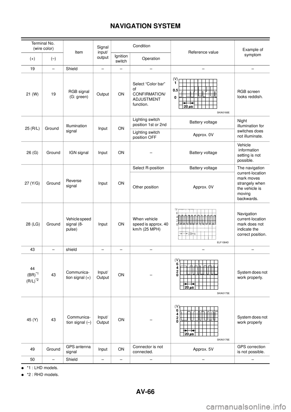
21 (W) 19RGB signal
(G: green)Output ONSelect “Color bar”
of
CONFIRMATION/
ADJUSTMENT
function.RGB screen
looks reddish.
25 (R/L) GroundIllumination
signalInput ONLighting switch
position 1st or 2ndBattery voltageNight
illumination for
switches does
not illuminate. Lighting switch
position OFFApprox. 0V
26 (G) Ground IGN signal Input ON – Battery voltageVehicle
information
setting is not
possible.
27 (Y/G) GroundReverse
signal Input ONSelect R-position Battery voltage The navigation
current-location
mark moves
strangely when
the vehicle is
moving
backwards. Other position Approx. 0V
28 (LG) GroundVehicle speed
signal (8-
pulse)Input ONWhen vehicle
speed is approx. 40
km/h (25 MPH)Navigation
current-location
mark does not
indicate the
correct position.
43 – shield – – – – –
44
(BR)
*1
(R/L)*243 Communica-
tion signal (+) Input/
OutputON –System does not
work properly.
45 (Y) 43Communica-
tion signal (–)Input/
OutputON –System does not
work properly
49 GroundGPS antenna
signalInput ONConnector is not
connected.Approx. 5VGPS correction
is not possible.
50 – Shield – – – – –Terminal No.
(wire color)
ItemSignal
input/
outputCondition
Reference valueExample of
symptom
(+) (–)Ignition
switchOperation
SKIA0166E
ELF1084D
SKIA0175E
SKIA0176E
Page 3957 of 4179
NAVIGATION SYSTEM
AV-67
C
D
E
F
G
H
I
J
L
MA
B
AV
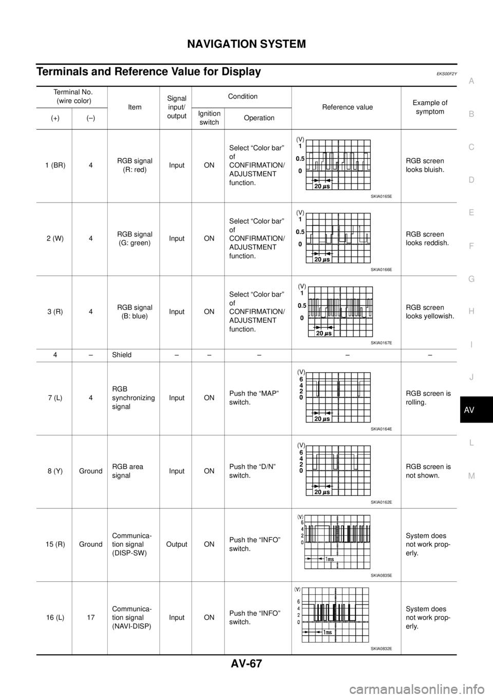
Terminals and Reference Value for DisplayEKS00F2Y
Terminal No.
(wire color)
ItemSignal
input/
outputCondition
Reference valueExample of
symptom
(+) (–)Ignition
switchOperation
1 (BR) 4RGB signal
(R: red)Input ONSelect “Color bar”
of
CONFIRMATION/
ADJUSTMENT
function.RGB screen
looks bluish.
2 (W) 4RGB signal
(G: green)Input ONSelect “Color bar”
of
CONFIRMATION/
ADJUSTMENT
function.RGB screen
looks reddish.
3 (R) 4RGB signal
(B: blue)Input ONSelect “Color bar”
of
CONFIRMATION/
ADJUSTMENT
function.RGB screen
looks yellowish.
4–Shield –– – – –
7 (L) 4RGB
synchronizing
signalInput ONPush the “MAP”
switch.RGB screen is
rolling.
8 (Y) GroundRGB area
signalInput ONPush the “D/N”
switch.RGB screen is
not shown.
15 (R) GroundCommunica-
tion signal
(DISP-SW)Output ONPush the “INFO”
switch.System does
not work prop-
erly.
16 (L) 17Communica-
tion signal
(NAVI-DISP)Input ONPush the “INFO”
switch.System does
not work prop-
erly.
SKIA0165E
SKIA0166E
SKIA0167E
SKIA0164E
SKIA0162E
SKIA0835E
SKIA0832E
Page 3958 of 4179
AV-68
NAVIGATION SYSTEM
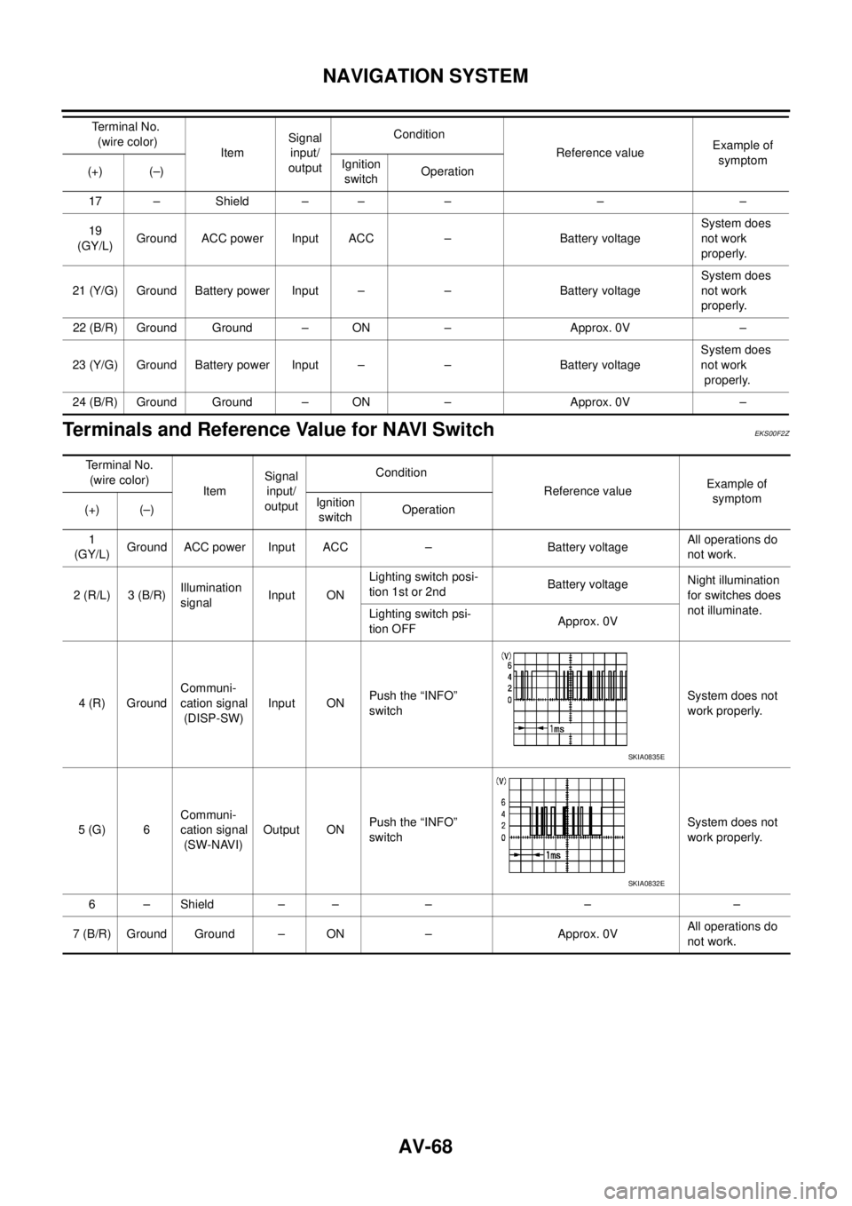
Terminals and Reference Value for NAVI SwitchEKS00F2Z
17 – Shield – – – – –
19
(GY/L)Ground ACC power Input ACC – Battery voltageSystem does
not work
properly.
21 (Y/G) Ground Battery power Input – – Battery voltageSystem does
not work
properly.
22 (B/R) Ground Ground – ON – Approx. 0V –
23 (Y/G) Ground Battery power Input – – Battery voltageSystem does
not work
properly.
24 (B/R) Ground Ground – ON – Approx. 0V –Terminal No.
(wire color)
ItemSignal
input/
outputCondition
Reference valueExample of
symptom
(+) (–)Ignition
switchOperation
Te r m i n a l N o .
(wire color)
ItemSignal
input/
outputCondition
Reference valueExample of
symptom
(+) (–)Ignition
switchOperation
1
(GY/L)Ground ACC power Input ACC – Battery voltageAll operations do
not work.
2 (R/L) 3 (B/R)Illumination
signalInput ONLighting switch posi-
tion 1st or 2ndBattery voltage Night illumination
for switches does
not illuminate.
Lighting switch psi-
tion OFFApprox. 0V
4 (R) GroundCommuni-
cation signal
(DISP-SW)Input ONPush the “INFO”
switchSystem does not
work properly.
5 (G) 6Communi-
cation signal
(SW-NAVI)Output ONPush the “INFO”
switchSystem does not
work properly.
6–Shield –– – – –
7 (B/R) Ground Ground – ON – Approx. 0VAll operations do
not work.
SKIA0835E
SKIA0832E
Page 3959 of 4179
NAVIGATION SYSTEM
AV-69
C
D
E
F
G
H
I
J
L
MA
B
AV
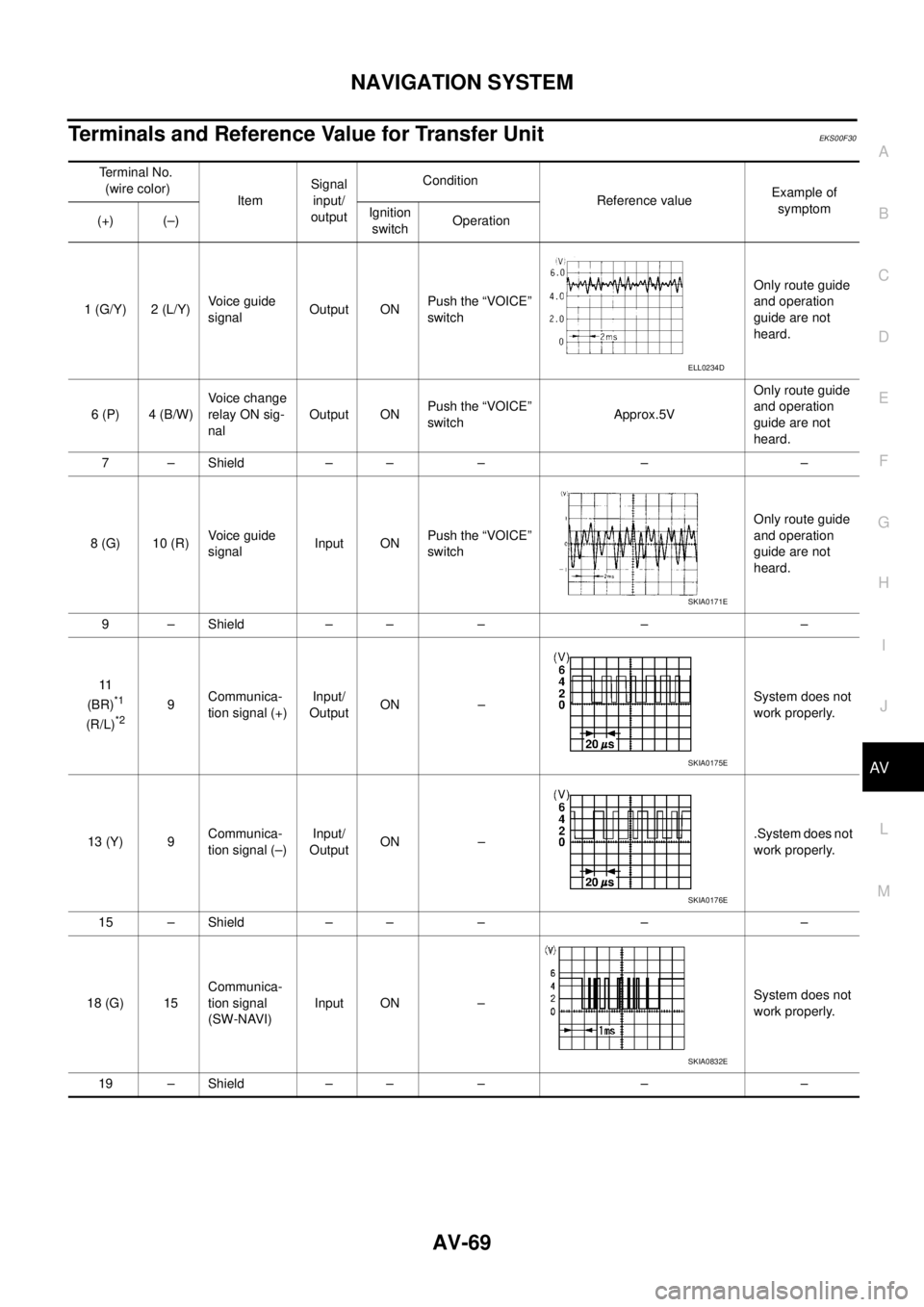
Terminals and Reference Value for Transfer UnitEKS00F30
Terminal No.
(wire color)
ItemSignal
input/
outputCondition
Reference valueExample of
symptom
(+) (–)Ignition
switchOperation
1 (G/Y) 2 (L/Y)Voice guide
signal Output ONPush the “VOICE”
switchOnly route guide
and operation
guide are not
heard.
6 (P) 4 (B/W)Voice change
relay ON sig-
nal Output ONPush the “VOICE”
switchApprox.5VOnly route guide
and operation
guide are not
heard.
7 – Shield – – – – –
8 (G) 10 (R)Voice guide
signalInput ONPush the “VOICE”
switchOnly route guide
and operation
guide are not
heard.
9 – Shield – – – – –
11
(BR)
*1
(R/L)*29Communica-
tion signal (+)Input/
OutputON –System does not
work properly.
13 (Y) 9Communica-
tion signal (–)Input/
OutputON –.System does not
work properly.
15 – Shield – – – – –
18 (G) 15Communica-
tion signal
(SW-NAVI)Input ON –System does not
work properly.
19 – Shield – – – – –
ELL0234D
SKIA0171E
SKIA0175E
SKIA0176E
SKIA0832E
Page 3960 of 4179
AV-70
NAVIGATION SYSTEM
�*1 : LHD models.
�*2 : RHD models.
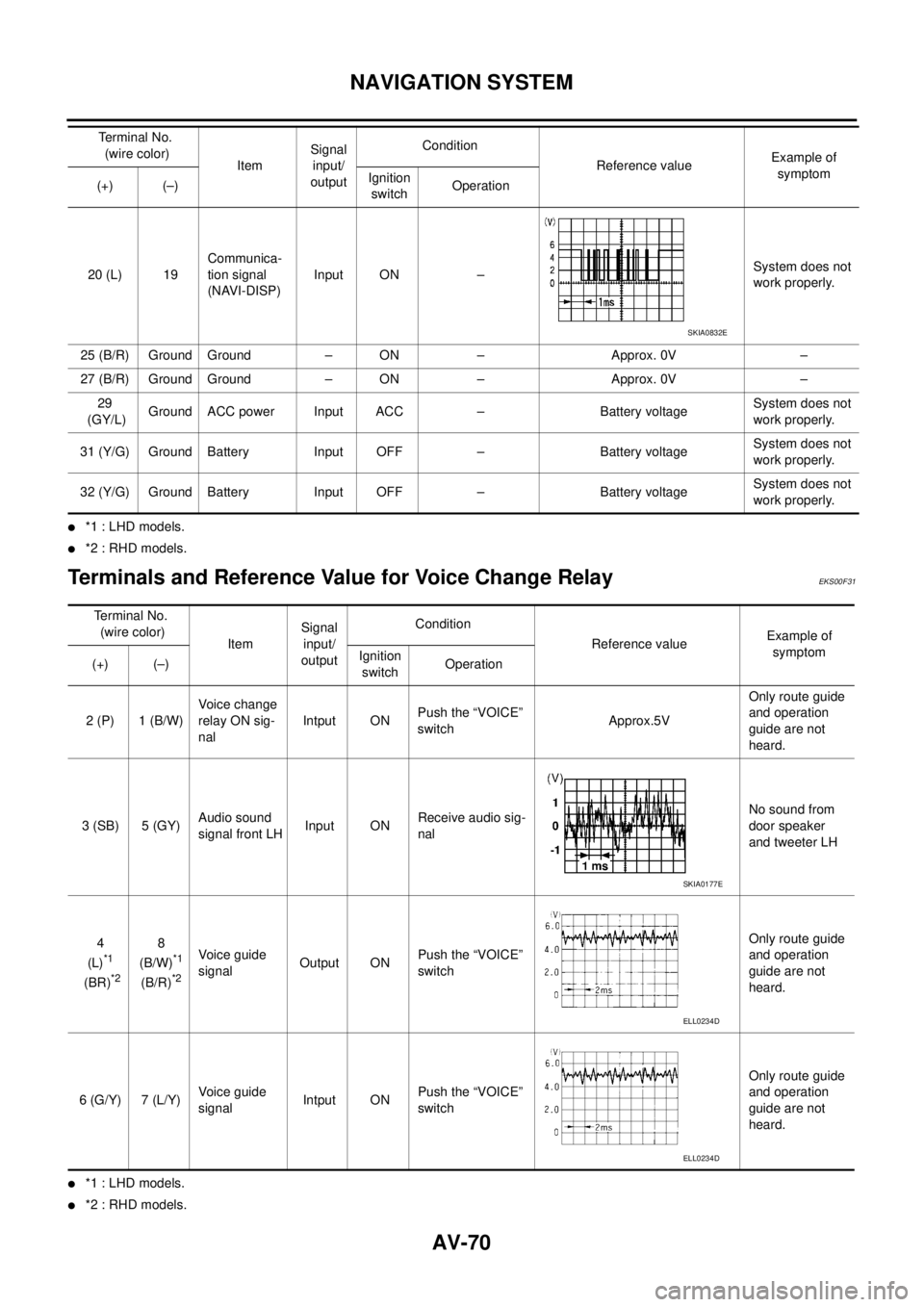
Terminals and Reference Value for Voice Change Relay EKS00F31
�*1 : LHD models.
�*2 : RHD models.20 (L) 19Communica-
tion signal
(NAVI-DISP)Input ON –System does not
work properly.
25 (B/R) Ground Ground – ON – Approx. 0V –
27 (B/R) Ground Ground – ON – Approx. 0V –
29
(GY/L)Ground ACC power Input ACC – Battery voltageSystem does not
work properly.
31 (Y/G) Ground Battery Input OFF – Battery voltageSystem does not
work properly.
32 (Y/G) Ground Battery Input OFF – Battery voltageSystem does not
work properly. Terminal No.
(wire color)
ItemSignal
input/
outputCondition
Reference valueExample of
symptom
(+) (–)Ignition
switchOperation
SKIA0832E
Terminal No.
(wire color)
ItemSignal
input/
outputCondition
Reference valueExample of
symptom
(+) (–)Ignition
switchOperation
2 (P) 1 (B/W)Voice change
relay ON sig-
nal Intput ONPush the “VOICE”
switchApprox.5VOnly route guide
and operation
guide are not
heard.
3 (SB) 5 (GY)Audio sound
signal front LHInput ONReceive audio sig-
nalNo sound from
door speaker
and tweeter LH
4
(L)
*1
(BR)*2
8
(B/W)*1
(B/R)*2
Voice guide
signal Output ONPush the “VOICE”
switchOnly route guide
and operation
guide are not
heard.
6 (G/Y) 7 (L/Y)Voice guide
signal Intput ONPush the “VOICE”
switchOnly route guide
and operation
guide are not
heard.
SKIA0177E
ELL0234D
ELL0234D
Page 3961 of 4179

NAVIGATION SYSTEM
AV-71
C
D
E
F
G
H
I
J
L
MA
B
AV
Self-Diagnosis FunctionEKS00F32
DESCRIPTION
�Diagnosis function consists of the self-diagnosis mode performed automatically and the CONFIRMATION/
ADJUSTMENT mode operated manually.
�Self-diagnosis mode checks for connections between the units constituting this system, analyzes each
individual unit at the same time, and displays the results on the LCD screen.
�CONFIRMATION/ADJUSTMENT mode is used to perform trouble diagnosis that require operation and
judgment by an operator (trouble that cannot be automatically judged by the system), to check/change the
set value, and to display the History of Errors of the navigation system.
DIAGNOSIS ITEM
Mode Description
Self-diagnosis
�NAVI Control unit diagnosis (DVD-ROM drive will not be diagnosed when no
map DVD-ROM is in it.).
�Performs diagnosis of each unit and connections between control unit and
GPS antenna, as well as between control unit and each unit.
Confirmation /
AdjustmentDisplayColor tone and shading of the screen can be checked by the display of a color
bar and a gray scale.
Vehicle signalsAnalyzes the following vehicle signals: Vehicle speed signal, light signal, igni-
tion switch signal, and reverse signal.
NavigationDisplay Longitude
& LatitudeDisplay the map. Use the joystick to adjust position. Longitude and latitude will
be displayed.
Speed CalibrationUnder ordinary conditions, the navigation system distance measuring function
will automatically compensate for minute decreases in wheel and tire diameter
caused by tire wear or low pressure. Speed calibration immediately restores
system accuracy in cases such as when distance calibration is needed
because of the use of tire chains in inclement weather.
Angle AdjustmentCorrects difference between actual turning angle of a vehicle and turning
angle of the car mark on the display.
Initialize LocationThis mode is for initializing the current location. Use when the vehicle is trans-
ported a long distance on a trailer, etc.
History of ErrorsDiagnosis results previously stored in the memory (before turning ignition
switch ON) are displayed in this mode. Time and location when/where the
errors occurred are also displayed.