Page 3962 of 4179

AV-72
NAVIGATION SYSTEM
Self-Diagnosis ModeEKS00F33
OPERATION PROCEDURE
1. Start the engine.
2. Push and hold “MAP” and “DAY/NIGHT” switches simulta-
neously for 5 seconds or more.
�Push the “BACK” switch and the initial system screen will be
shown.
3. The initial trouble diagnosis screen will be shown, and items
“Self-Diagnosis” and “Confirmetion / Adjustment” will become
selective.
4. Perform self-diagnosis by selecting the “Self-Diagnosis”.
�Self-diagnosis subdivision screen will be shown and the oper-
ation enters the self-diagnosis mode.
�A bar graph shown below the self-diagnosis subdivision
screen indicates progress of the diagnosis.
5. On the “SELF-DIAGNOSIS” screen, each unit name will be col-
ored according to the diagnosis result, as follows.
�If several malfunctions are present in a unit, color of its switch
on the screen will be either red, yellow, or gray, determined by
the malfunction of the highest priority.
�Lines between navigation unit and GPS antenna are green or
yellow based on diagnosis results.
�Lines between control unit and units other than those above are gray regardless of diagnosis results.
CAUTION:
�Navigation Unit = NAVI control unit
�Communication converter = Transfer unit
�Satellite Switch = NAVI switch
SKIA9191E
SKIA0381E
SKIA0382E
Green : No malfunctioning.
Yellow : Cannot be judged by self-diagnosis results.
Red : Unit is malfunctioning.
Gray : Diagnosis has not been done.
SKIA9192E
Page 3963 of 4179
NAVIGATION SYSTEM
AV-73
C
D
E
F
G
H
I
J
L
MA
B
AV
6. Select a switch on the “SELF-DIAGNOSIS” screen and com-
ments for the diagnosis results will be shown.
�When the switch is green, the following comment will be
shown. “Self-Diagnosis was successful. Further diagnosis
and adjustments are recommended. Follow the “confirmation
and adjustments” menu or refer to the service manual.”.
�When the switch is yellow, the following comment will be
shown. “Connection to the following unit is not responding.
See the service manual for further diagnosis”.
�When the switch is red, the following comment will be shown.
“Navigation Unit is abnormal”.
�When the switch is gray, the following comment will be shown. “Self-diagnosis for DVD-ROM DRIVER
of NAVI was not conducted because no DVD-ROM was available.”
SKIA9193E
Page 3964 of 4179

AV-74
NAVIGATION SYSTEM
SELF–DIAGNOSIS RESULT
Quick reference table
1. Select an applicable diagnosis No. in the diagnosis result quick reference table.
2. Find estimated malfunctioning system in the diagnosis No. table and perform check.
3. Turn the ignition switch to OFF and perform self-diagnosis again.
Diagnosis result quick reference table
CAUTION:
Check the following when the self-diagnosis mode cannot be used.
�NAVI control unit power supply and ground.
�Display power supply and ground.
�NAVI switch power supply and ground.
�Transfer unit power supply and ground.
�AV communication line between NAVI switch and Display, AV communication line between Display and Transfer unit, AV communica-
tion line between Transfer unit and NAVI control unit.
Method of diagnosis for malfunctioning system
�When system does not start, indicate malfunction connection between units by outbreak sound from sys-
tem.
Diagnosis procedure.
1. Turn ignition switch ON. Make sure whether or not route guide start sound which is output from NAVI con-
trol unit indicate 10 seconds after.
2. Push and hold “MAP” and “DAY/NIGHT” switches simultaneously for 5 seconds or more. Make sure
whether or not 2 times of beep sound or route guide start sound indicate.
3. According to the former two steps , Select an proper diagnosis No. in the diagnosis result quick reference
table.
4. Find estimated malfunctioning system from the diagnosis No. table and perform check.
Diagnosis result quick reference table
*:Indicated when pushing both “MAP” and “DAY/NIGHT” simultaneously. (Unnecessary to push them 5 seconds or more.)Screen switch
Diagnosis No.
Switch color Navigation Unit GPS antenna
Red×1
Gray×2
Ye l l o w×3
×4
××5
Procedure 1 Procedure 2
Diagnosis No.
10 seconds after turn ignition switch ON.Push and hold “MAP” and “DAY/NIGHT” switches
simultaneously for 5 seconds or more.
Route guide start sound appearsRoute guide start sound indicates 6
There is no sound 7
There is no soundTwo times of beep sound from NAVI switch * 8
There is no sound 9
Page 3965 of 4179

NAVIGATION SYSTEM
AV-75
C
D
E
F
G
H
I
J
L
MA
B
AV
Self–diagnosis codes
CONFIRMATION/ADJUSTMENT ModeEKS00F34
OPERATION PROCEDURE
1. Start the engine.
2. Push and hold “MAP” and “DAY/NIGHT” switches simulta-
neously for 5 seconds or more.
�Push the “BACK” switch and the initial system screen will be
shown.
3. The initial trouble diagnosis screen will be shown, and items
“Self-Diagnosis” and “Confirmation / Adjustment” will become
selective.
Diagnosis
No.Possible causeReference
page
1 NAVI control unit malfunction–
2 NAVI control unit judged no map DVD-ROM is inserted. –
3When “DVD-ROM error. Please check disc.” is shown.
1. Eject map DVD-ROM and check if it is compatible with the system.
2. Check ejected DVD-ROM for dirt, damage, and warpage.
3. If no error is found, insert a known good map DVD-ROM of the same type and perform self-diagnosis
again. If same result is shown, the NAVI control unit is malfunctioning. If result is normal, the map DVD-
ROM is malfunctioning.–
4If “Error found in DVD-ROM or DVD-ROM driver in control unit. Please perform diagnosis in accordance
with service manual” is shown, carry out same inspection as diagnosis No. 3.–
5GPS antenna system
1. Visually check for a broken wire in the GPS antenna coaxial cable.
2. Disconnect the GPS antenna connector and check that approximately 5V is supplied from NAVI control
unit. If not, the NAVI control unit is inoperative. If the voltage is supplied, replace the GPS antenna and
perform self-diagnosis again. If the same result is shown, the NAVI control unit is inoperative.–
6Display power supply and ground circuit.
Communication line between display and NAVI switch. Refer to
AV- 8 6
7NAVI switch power supply and ground circit.
Communication line between NAVI switch and transfer unit.Refer to
AV- 8 6
8NAVI control unit power supply and ground circuit.
Communication line between NAVI control unit and transfer unit.Refer to
AV- 8 7
9Transfer unit power supply and ground circuit.
Communication line between transfer unit and display.Refer to
AV- 8 8
SKIA9191E
SKIA0381E
Page 3966 of 4179
AV-76
NAVIGATION SYSTEM
4. When “Confirmation / Adjustment” is selected on the initial trou-
ble diagnosis screen, the operation will enter the CONFIRMA-
TION/ADJUSTMENT mode. In this mode, check and adjustment
of each item will become possible.
5. Select each switch on “Confirmation / Adjustment” screen to dis-
play the relevant diagnosis screen.
DISPLAY
CAUTION:
When Display Color Spectrum Bar screen is completed after “BACK” switch is Pushed, the screen
color changes once. This is normal.
�When RGB signal error occurred in the RGB system, tone of the color bar will change as follows.
�When the color of the screen looks unusual, refer to AV- 9 1 , "Color of RGB Image Is Not Proper" .
SKIA9190E
SKIA2251E
R (red) signal error : Screen looks bluish.
G (green) signal error : Screen looks reddish.
B (blue) signal error : Screen looks yellowish.
Page 3967 of 4179
NAVIGATION SYSTEM
AV-77
C
D
E
F
G
H
I
J
L
MA
B
AV
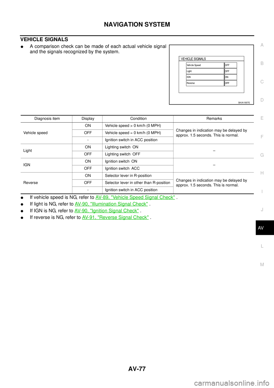
VEHICLE SIGNALS
�A comparison check can be made of each actual vehicle signal
and the signals recognized by the system.
�If vehicle speed is NG, refer to AV- 8 9 , "Vehicle Speed Signal Check" .
�If light is NG, refer to AV- 9 0 , "Illumination Signal Check" .
�If IGN is NG, refer to AV- 9 0 , "Ignition Signal Check" .
�If reverse is NG, refer to AV- 9 1 , "Reverse Signal Check" .
SKIA1997E
Diagnosis item Display Condition Remarks
Vehicle speedON Vehicle speed > 0 km/h (0 MPH)
Changes in indication may be delayed by
approx. 1.5 seconds. This is normal. OFF Vehicle speed = 0 km/h (0 MPH)
- Ignition switch in ACC position
LightON Lighting switch ON
–
OFF Lighting switch OFF
IGNON Ignition switch ON
–
OFF Ignition switch ACC
ReverseON Selector lever in R-position
Changes in indication may be delayed by
approx. 1.5 seconds. This is normal. OFF Selector lever in other than R-position
- Ignition switch in ACC position
Page 3968 of 4179
AV-78
NAVIGATION SYSTEM
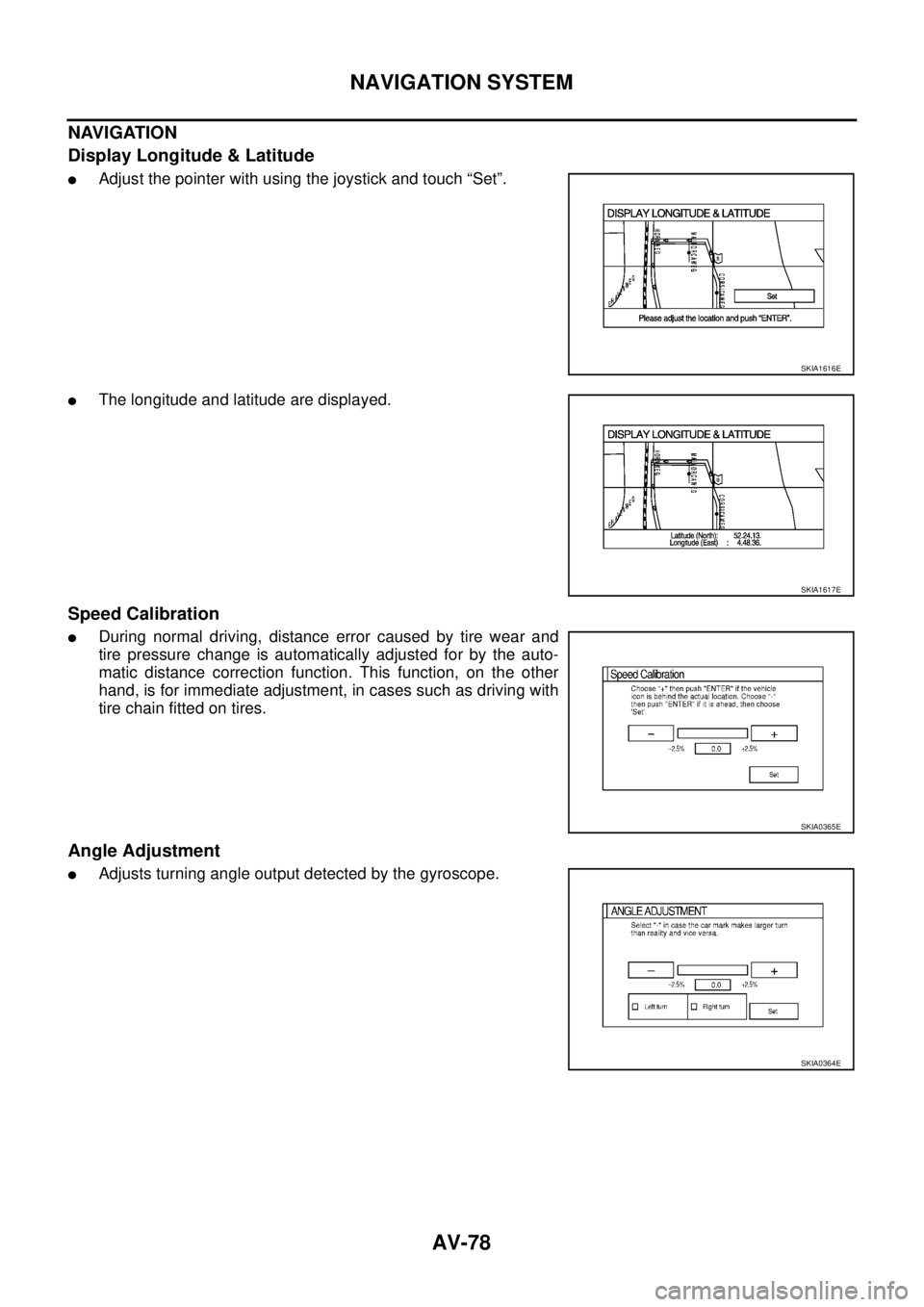
NAVIGATION
Display Longitude & Latitude
�Adjust the pointer with using the joystick and touch “Set”.
�The longitude and latitude are displayed.
Speed Calibration
�During normal driving, distance error caused by tire wear and
tire pressure change is automatically adjusted for by the auto-
matic distance correction function. This function, on the other
hand, is for immediate adjustment, in cases such as driving with
tire chain fitted on tires.
Angle Adjustment
�Adjusts turning angle output detected by the gyroscope.
SKIA1616E
SKIA1617E
SKIA0365E
SKIA0364E
Page 3969 of 4179
NAVIGATION SYSTEM
AV-79
C
D
E
F
G
H
I
J
L
MA
B
AV
Initialize Location
Description
�Location data for GPS in the Center control unit is intialized in Europe by this mode. Then it is possible for
Center control unit to receive GPS signals for short time.
How to perform “Initialize Location” mode
1. select “Initialize Location”, and push “ENTER”.
2. A message “Plese wait.” is displayed and then backs to another
display of “Confirmation/Adjustment” mode.
NOTE:
�To continue GPS initialized operation, operate as follows back to
“Map” screen.
–Push “BACK” button teice.
–Push “MAP” button.
�After above operation, GPS indicator changes to green color
within half a minute, unless improper GPS located condition.
�This operation should be performed in out side field.
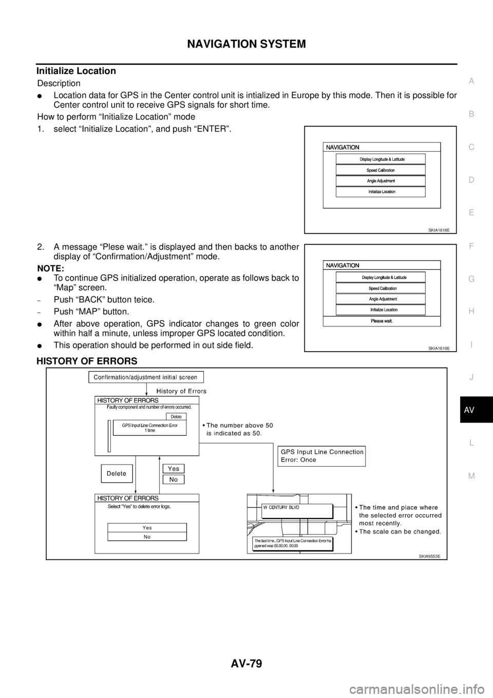
HISTORY OF ERRORS
SKIA1618E
SKIA1619E
SKIA9553E