Page 1884 of 4179
![NISSAN X-TRAIL 2003 Service Repair Manual FL-6
[QR]
FUEL LEVEL SENSOR UNIT, FUEL FILTER AND FUEL PUMP ASSEMBLY
CAUTION:
�Quick connector can be removed when the tabs are
completely depressed. Do not twist it more than neces-
sary.
�Do not u](/manual-img/5/57404/w960_57404-1883.png "NISSAN X-TRAIL 2003 Service Repair Manual FL-6
[QR]
FUEL LEVEL SENSOR UNIT, FUEL FILTER AND FUEL PUMP ASSEMBLY
CAUTION:
�Quick connector can be removed when the tabs are
completely depressed. Do not twist it more than neces-
sary.
�Do not u")
FL-6
[QR]
FUEL LEVEL SENSOR UNIT, FUEL FILTER AND FUEL PUMP ASSEMBLY
CAUTION:
�Quick connector can be removed when the tabs are
completely depressed. Do not twist it more than neces-
sary.
�Do not use any tools to disconnect quick connector.
�Keep resin tube away from heat. Be especially careful
when welding near the tube.
�Prevent acid liquid such as battery electrolyte, etc.
from getting on resin tube.
�Do not bend or twist resin tube during installation and
disconnection.
�Do not remove the remaining retainer on hard tube (or
equivalent) except when resin tube or retainer is
replaced.
�When resin tube or hard tube (or equivalent) is
replaced, also replace retainer with a new one.
�To keep the connecting portion clean and to avoid
damage and foreign materials, cover them completely
with plastic bags or something similar.
8. Using a fuel tank lock ring wrench (commercial service tool),
remove lock ring.
9. Remove main fuel level sensor unit, fuel filter and fuel pump assembly, and sub fuel level sensor unit as
follows.
CAUTION:
�Do not bend float arm during removal.
�Avoid impacts such as falling when handling components.Retainer color: Green
SBIA0504E
PBIC0163E
PBIC0240E
Page 1892 of 4179
FL-14
[QR]
SERVICE DATA AND SPECIFICATIONS (SDS)
SERVICE DATA AND SPECIFICATIONS (SDS)PFP:00030
Standard and LimitEBS00KOX
FUEL TANK
Tightening TorqueEBS00KOY
Unit: N·m (kg-m, ft-lb)
Unit: N·m (kg-m, in-lb)* Fuel tank capacity
Approx. 60 (13-1/4 Imp gal)
Lock ring32.9 (3.4, 24)
Fuel tank band 27.4 - 35.3 (2.8 - 3.6, 21 - 26)
Fuel tank protector 4.3 - 5.8 (0.43 - 0.59, 38 - 51)*
Fuel filler tube 7.8 - 10.4 (0.80 - 1.0, 69 - 92)*
Vent tube7.8 - 10.4 (0.80 - 1.0, 69 - 92)*
Page 1893 of 4179
PREPARATION
FL-15
[YD22DDTi]
C
D
E
F
G
H
I
J
K
L
MA
FL
[YD22DDTi]PREPARATIONPFP:00002
Commercial Service ToolsEBS00BKG
Tool nameDescription
Fuel filter wrench Removing fuel filter
Fuel tank lock ring wrench Removing and installing fuel tank lock ring
PBIC0519E
ZZA0122D
Page 1897 of 4179
![NISSAN X-TRAIL 2003 Service Repair Manual FUEL LEVEL SENSOR UNIT
FL-19
[YD22DDTi]
C
D
E
F
G
H
I
J
K
L
MA
FL
FUEL LEVEL SENSOR UNITPFP:17042
Removal and InstallationEBS00BLD
REMOVAL
WARNING:
Be sure to read “General Precautions” When wor](/manual-img/5/57404/w960_57404-1896.png "NISSAN X-TRAIL 2003 Service Repair Manual FUEL LEVEL SENSOR UNIT
FL-19
[YD22DDTi]
C
D
E
F
G
H
I
J
K
L
MA
FL
FUEL LEVEL SENSOR UNITPFP:17042
Removal and InstallationEBS00BLD
REMOVAL
WARNING:
Be sure to read “General Precautions” When wor")
FUEL LEVEL SENSOR UNIT
FL-19
[YD22DDTi]
C
D
E
F
G
H
I
J
K
L
MA
FL
FUEL LEVEL SENSOR UNITPFP:17042
Removal and InstallationEBS00BLD
REMOVAL
WARNING:
Be sure to read “General Precautions” When working on fuel system. Refer to FL-16, "
General Precau-
tions" .
1. Open fuel filler lid.
2. Open the fuel filler cap and release the pressure inside fuel tank.
3. Check fuel level on level place. If gauge indicates more than the
level shown in figure (full or almost full), drain fuel from fuel tank
until gauge indicates level shown in figure or below.
�Refer to the following for draining fuel.
a. Insert fuel tube of less than 25 mm (0.98 in) in diameter into fuel
filler tube through fuel filler opening to draw fuel from fuel filler
tube.
b. Disconnect fuel filler hose from fuel filler tube.
c. Insert fuel tube into fuel tank through fuel filler hose to draw fuel
from fuel tank.
�As a guide, fuel level becomes the position shown in figure or
below when approximately 15 liter (13-1/4 lmp qt) of fuel are drained from full tank.
NOTE:
Adjusting fuel level is to prevent fuel from spilling, when fuel level sensor unit is removed.
4. Disconnect negative battery terminal.
5. Lift to fold rear seat cushion up. Refer to SE-31, "
REAR SEAT" .
6. Peel off floor carpet, then remove inspection hole cover.
1. Lock ring 2. Main fuel level sensor unit 3. Seal packing
4. Chamber 5. Sub fuel level sensor unit
PBIC2031E
FEL0403D
Page 1898 of 4179
FL-20
[YD22DDTi]
FUEL LEVEL SENSOR UNIT
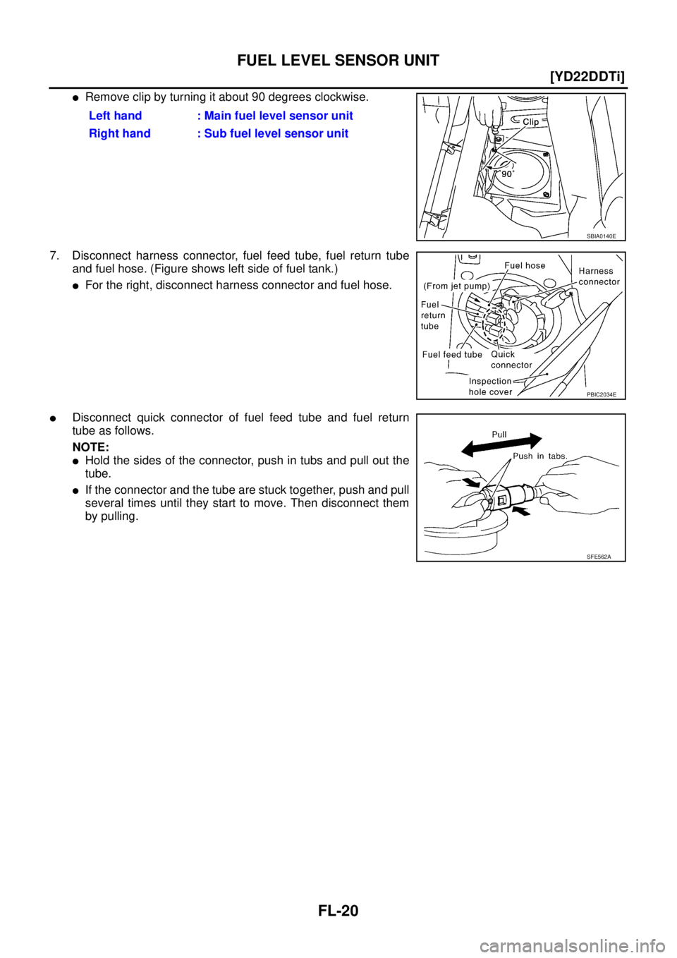
�Remove clip by turning it about 90 degrees clockwise.
7. Disconnect harness connector, fuel feed tube, fuel return tube
and fuel hose. (Figure shows left side of fuel tank.)
�For the right, disconnect harness connector and fuel hose.
�Disconnect quick connector of fuel feed tube and fuel return
tube as follows.
NOTE:
�Hold the sides of the connector, push in tubs and pull out the
tube.
�If the connector and the tube are stuck together, push and pull
several times until they start to move. Then disconnect them
by pulling.Left hand : Main fuel level sensor unit
Right hand : Sub fuel level sensor unit
SBIA0140E
PBIC2034E
SFE562A
Page 1899 of 4179
![NISSAN X-TRAIL 2003 Service Repair Manual FUEL LEVEL SENSOR UNIT
FL-21
[YD22DDTi]
C
D
E
F
G
H
I
J
K
L
MA
FL
CAUTION:
�The quick connector can be removed when the tabs are
completely depressed. Do not twist it more than neces-
sary.
�Do not](/manual-img/5/57404/w960_57404-1898.png "NISSAN X-TRAIL 2003 Service Repair Manual FUEL LEVEL SENSOR UNIT
FL-21
[YD22DDTi]
C
D
E
F
G
H
I
J
K
L
MA
FL
CAUTION:
�The quick connector can be removed when the tabs are
completely depressed. Do not twist it more than neces-
sary.
�Do not")
FUEL LEVEL SENSOR UNIT
FL-21
[YD22DDTi]
C
D
E
F
G
H
I
J
K
L
MA
FL
CAUTION:
�The quick connector can be removed when the tabs are
completely depressed. Do not twist it more than neces-
sary.
�Do not use any tools to disconnect quick connector.
�Keep the resin tube away from heat. Be especially careful
when welding near the tube.
�Prevent acid liquid such as battery electrolyte etc. from
getting on resin tube.
�Do not bend or twist the tube during installation and
removal.
�Do not remove the remaining retainer on hard tube (or
equivalent) except when resin tube or retainer is
replaced.
�When resin tube or fuel level sensor unit is replaced, also
replace retainer with a new one.
�To keep clean the connecting portion and to avoid dam-
age and foreign materials, cover them completely with
plastic bags or something similar.
8. Using a fuel tank lock ring wrench (commercial service tool),
remove the lock ring.
9. Remove main fuel level sensor unit (Left hand) and sub fuel level sensor unit (Right hand).
CAUTION:
�Do not bend the float arm during removal.
�Avoid impacts such as falling when handling components.
Left hand (main fuel level sensor unit):
�If necessary, remove the chamber from the bottom of the fuel tank.
�Remove the chamber by sliding toward the rear of the vehicle.Retainer color : Green (Fuel feed tube)
: Gray (Fuel return tube)
SBIA0504E
PBIC0163E
PBIC0240E
Page 1904 of 4179
FL-26
[YD22DDTi]
SERVICE DATA AND SPECIFICATIONS (SDS)
SERVICE DATA AND SPECIFICATIONS (SDS)PFP:00030
Standard and LimitEBS00BL5
Tightening TorqueEBS00BL6
Unit: N·m (kg-m, ft-lb)
Unit: N·m (kg-m, in-lb)* Fuel tank capacity
Approx. 60 (13-1/4 Imp gal)
Fuel filter drain plug4.9 (0.50, 43)*
Fuel tank band31.4 (3.2, 23)
Fuel filler tube 9.1 (0.93, 81)*
Vent tube9.1 (0.93, 81)*
Lock ring32.9 (3.4, 24)
Fuel transport pump4.8 (0.49, 42)*
Page 1919 of 4179

CLUTCH PEDAL
CL-5
D
E
F
G
H
I
J
K
L
MA
B
CL
CLUTCH PEDALPFP:46540
On-Vehicle Inspection and AdjustmentECS001WB
1. Check to see if clevis pin floats freely in bore of clutch pedal. It
should not be bound by clevis or clutch pedal.
a. If clevis pin is not free, check that pedal stopper bolt is not apply-
ing pressure to clutch pedal causing clevis pin to bind. To adjust,
loosen lock nut and turn pedal stopper bolt.
b. Tighten lock not.
c. Verify that clevis pin floats in bore of clutch pedal. It should not
be bound by clutch pedal.
d. If clevis pin is still not free, remove clevis pin and check for
deformation or damage. Replace clevis pin if necessary. Leave
clevis pin removed for step 2.
2. Check clutch pedal stroke for free range of movement.
a. With clevis pin removed, manually move clutch pedal up and
down to determine if it moves freely.
b. If any sticking is noted, replace related parts (clutch pedal
bracket, assist spring, bushing etc.). Reassemble clutch pedal
and re-verifity that clevis pin floats freely in bore of clutch pedal.
3. Check clutch hydraulic and system components (clutch master cylinder, clutch operating cylinder, clutch
withdrawal lever, clutch release bearing, etc.) for sticking or binding.
a. If any sticking or binding noted, repair or replace related parts as necessary.
b. If hydraulic system repair was necessary, bleed the clutch hydraulic system. Refer to CL-7, "
Air Bleeding
Procedure" .
NOTE:
Do not use a vacuum assist or any other type of power bleeder on this system. Use of a vacuum assist or
power bleeder will not purge all the air from the system.
PCIB0814E
![NISSAN X-TRAIL 2003 Service Repair Manual FL-14
[QR]
SERVICE DATA AND SPECIFICATIONS (SDS)
SERVICE DATA AND SPECIFICATIONS (SDS)PFP:00030
Standard and LimitEBS00KOX
FUEL TANK
Tightening TorqueEBS00KOY
Unit: N·m (kg-m, ft-lb)
Unit: N·m (kg](/manual-img/5/57404/w960_57404-1891.png "NISSAN X-TRAIL 2003 Service Repair Manual FL-14
[QR]
SERVICE DATA AND SPECIFICATIONS (SDS)
SERVICE DATA AND SPECIFICATIONS (SDS)PFP:00030
Standard and LimitEBS00KOX
FUEL TANK
Tightening TorqueEBS00KOY
Unit: N·m (kg-m, ft-lb)
Unit: N·m (kg")
![NISSAN X-TRAIL 2003 Service Repair Manual PREPARATION
FL-15
[YD22DDTi]
C
D
E
F
G
H
I
J
K
L
MA
FL
[YD22DDTi]PREPARATIONPFP:00002
Commercial Service ToolsEBS00BKG
Tool nameDescription
Fuel filter wrench Removing fuel filter
Fuel tank lock rin](/manual-img/5/57404/w960_57404-1892.png "NISSAN X-TRAIL 2003 Service Repair Manual PREPARATION
FL-15
[YD22DDTi]
C
D
E
F
G
H
I
J
K
L
MA
FL
[YD22DDTi]PREPARATIONPFP:00002
Commercial Service ToolsEBS00BKG
Tool nameDescription
Fuel filter wrench Removing fuel filter
Fuel tank lock rin")
![NISSAN X-TRAIL 2003 Service Repair Manual FL-26
[YD22DDTi]
SERVICE DATA AND SPECIFICATIONS (SDS)
SERVICE DATA AND SPECIFICATIONS (SDS)PFP:00030
Standard and LimitEBS00BL5
Tightening TorqueEBS00BL6
Unit: N·m (kg-m, ft-lb)
Unit: N·m (kg-m,](/manual-img/5/57404/w960_57404-1903.png "NISSAN X-TRAIL 2003 Service Repair Manual FL-26
[YD22DDTi]
SERVICE DATA AND SPECIFICATIONS (SDS)
SERVICE DATA AND SPECIFICATIONS (SDS)PFP:00030
Standard and LimitEBS00BL5
Tightening TorqueEBS00BL6
Unit: N·m (kg-m, ft-lb)
Unit: N·m (kg-m,")