Page 1923 of 4179

CLUTCH MASTER CYLINDER
CL-9
D
E
F
G
H
I
J
K
L
MA
B
CL
�Drain clutch fluid from reservoir tank and remove hose.
�Remove hose from nipple. Immediately plug hose and reservoir tank to prevent clutch fluid from drip-
ping.
CAUTION:
Do not spill clutch fluid onto painted surfaces. If it spills, wipe up immediately and wash the
affected area with water.
2. Using a flare nut torque wrench, remove clutch tube.
3. Remove snap pin and clevis pin on clevis in passenger compartment to separate clutch pedal.
4. First remove mounting nuts on master cylinder assembly, and then master cylinder assembly from vehi-
cle.
INSTALLATION
1. Connect clutch tube to master cylinder assembly and temporarily tighten flare nut.
2. Install master cylinder assembly and tighten mounting nut to the specified torque. Refer to CL-8,
"Removal and Installation" .
3. Using a flare nut torque wrench, tighten clutch tube flare nut to the specified torque. Refer to CL-11,
"Removal and Installation" .
4. Attach clevis of clevis pin to clutch pedal.
5. Attach snap pin to clevis pin.
6. Install hose to nipple.
7. After completing this procedure, inspect and adjust pedal height and then bleed clutch tube. Refer to CL-
5, "On-Vehicle Inspection and Adjustment" , CL-7, "Air Bleeding Procedure"
Disassembly and AssemblyECS008BB
DISASSEMBLY
1. Remove spring pin, nipple and seal from cylinder body using a
pin punch.
2. Loosen push rod lock nut. Remove clevis and lock nut.
3. Remove seat.
4. Remove stopper ring and stopper. Remove push rod from cylin-
der body while holding it securely to reduce possibility of the pis-
ton popping out.
5. Remove piston assembly and return spring.
INSPECTION AFTER DISASSEMBLY
Check for any of the conditions shown below. If any malfunction is found, replace the part concerned.
�Damaged cylinder internal wall, foreign matter, wear, corrosion, or pinhole
�Damaged or deformed nipple or reservoir tank
�Settling of spring
�Cracked or deformed seat
ASSEMBLY
1. Apply rubber lubricant to internal surface of cylinder body, sliding surface of piston assembly, and piston
cup. Insert piston assembly and return spring.
2. Apply silicon grease to push rod and install stopper. Install stopper ring while holding down push rod by
hand to prevent piston assembly from popping out.
3. Install seat.
4. Install clevis to push rod and tighten lock nut to the specified torque. Refer to CL-8, "
Removal and Installa-
tion" .
5. Install seal and nipple to cylinder body. Install spring pin, using a pin punch.
PCIB0274E
Page 1925 of 4179
CLUTCH PIPING
CL-11
D
E
F
G
H
I
J
K
L
MA
B
CL
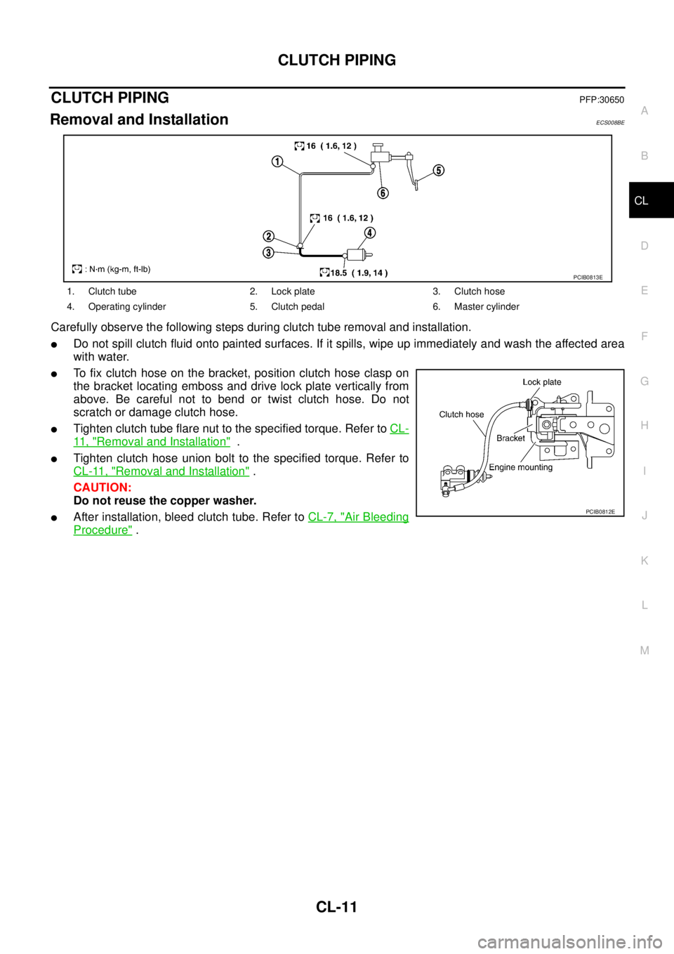
CLUTCH PIPINGPFP:30650
Removal and InstallationECS008BE
Carefully observe the following steps during clutch tube removal and installation.
�Do not spill clutch fluid onto painted surfaces. If it spills, wipe up immediately and wash the affected area
with water.
�To fix clutch hose on the bracket, position clutch hose clasp on
the bracket locating emboss and drive lock plate vertically from
above. Be careful not to bend or twist clutch hose. Do not
scratch or damage clutch hose.
�Tighten clutch tube flare nut to the specified torque. Refer to CL-
11 , "Removal and Installation" .
�Tighten clutch hose union bolt to the specified torque. Refer to
CL-11, "
Removal and Installation" .
CAUTION:
Do not reuse the copper washer.
�After installation, bleed clutch tube. Refer to CL-7, "Air Bleeding
Procedure" .
1. Clutch tube 2. Lock plate 3. Clutch hose
4. Operating cylinder 5. Clutch pedal 6. Master cylinder
PCIB0813E
PCIB0812E
Page 1946 of 4179
MT-14
CONTROL LINKAGE
CONTROL LINKAGEPFP:34103
Components of Control Device and CableECS008BV
1. Control lever knob 2. Select cable 3. Shift cable
4. Lock plate 5. Lock plate 6. Clutch housing
7. Cable mounting bracket 8. Control device assembly 9. Control lever
10. Lock plate 11. Washer 12. Snap pin
13. Washer
PCIB0777E
Page 1947 of 4179
CONTROL LINKAGE
MT-15
D
E
F
G
H
I
J
K
L
MA
B
MT
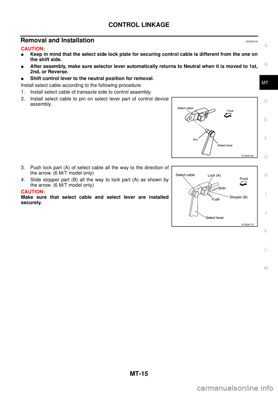
Removal and InstallationECS00CY6
CAUTION:
�Keep in mind that the select side lock plate for securing control cable is different from the one on
the shift side.
�After assembly, make sure selector lever automatically returns to Neutral when it is moved to 1st,
2nd, or Reverse.
�Shift control lever to the neutral position for removal.
Install select cable according to the following procedure.
1. Install select cable of transaxle side to control assembly.
2. Install select cable to pin on select lever part of control device
assembly.
3. Push lock part (A) of select cable all the way to the direction of
the arrow. (6 M/T model only)
4. Slide stopper part (B) all the way to lock part (A) as shown by
the arrow. (6 M/T model only)
CAUTION:
Make sure that select cable and select lever are installed
securely.
PCIB0815E
PCIB0817E
Page 1954 of 4179
MT-22
TRANSAXLE ASSEMBLY
SHIFT CONTROL COMPONENTS
1. 3rd-4th bracket 2. Retaining pin 3. Stopper ring
4. 5th-reverse bracket 5. Reverse lever assembly 6. Shifter cap
7. Reverse shift fork 8. Reverse fork rod 9. Check plug
10. Check spring 11. Shift check sleeve 12. Check ball
13. 5th-reverse fork rod 14. 5th shift fork 15. Check spring
16. 3rd-4th fork rod 17. Interlock pin 18. Shift check sleeve
19. 1st-2nd fork rod 20. 1st-2nd bracket 21. 1st-2nd shift fork
22. 3rd-4th shift fork 23. Control assembly 24. Stopper bolt
25. Shift check 26. O-ring
PCIB0784E
Page 1959 of 4179
TRANSAXLE ASSEMBLY
MT-27
D
E
F
G
H
I
J
K
L
MA
B
MT
SHIFT CONTROL COMPONENTS
1. 3rd-4th bracket 2. Retaining pin 3. Check plug
4. 5th-6th bracket 5. Stopper ring 6. Reverse bracket
7. Reverse lever assembly 8. Shifter cap 9. Reverse shift fork
10. Reverse fork rod 11. Check spring 12. Shift check sleeve
13. Check ball 14. Reverse bracket fork rod 15. 5th-6th shift fork
16. 5th-6th fork rod 17. Interlock pin 18. Shift check sleeve
19. Check spring 20. Check spring 21. 3rd-4th fork rod
22. 3rd-4th shift fork 23. 1st-2nd fork rod 24. 1st-2nd fork rod bracket
25. 1st-2nd shift fork 26. Stopper bolt 27. Shift check
28. O-ring 29. Control assembly
PCIB0788E
Page 1962 of 4179

MT-30
TRANSAXLE ASSEMBLY
14. With shift lever in 5th position, remove mounting bolts from
reverse lever assembly. Lift reverse lever assembly to remove.
CAUTION:
Be careful not to lose shifter cap.
15. Pull out reverse fork rod then remove reverse shift fork.
16. Shift 3rd-4th fork rod to 3rd position. Remove retaining pin of 5th
shift fork using a pin punch.
17. Remove stopper rings for 5th-reverse bracket.
18. Pull out 5th-reverse fork rod and remove 5th shift fork and 5th-
reverse bracket.
19. Remove check balls (2 pieces) from clutch housing.
20. Remove retaining pin of 3rd-4th bracket using a pin punch.
21. Remove stopper rings for 3rd-4th shift fork.
22. Pull out 3rd-4th fork rod and remove 3rd-4th shift fork and 3rd-
4th bracket.
23. Remove interlock pin and shift check sleeve from clutch hous-
ing.
24. Remove retaining pin of 1st-2nd shift fork using a pin punch.
25. Pull out 1st-2nd fork rod with 1st-2nd bracket.
26. Remove 1st-2nd shift fork.
27. Remove retaining pin of 1st-2nd bracket using a pin punch and
separate 1st-2nd fork rod and 1st-2nd bracket.
SCIA0390E
SCIA0391E
SCIA0392E
SCIA0393E
SCIA0394E
Page 1966 of 4179

MT-34
TRANSAXLE ASSEMBLY
9. Install 1st-2nd bracket onto 1st-2nd fork rod, and then install a
new retaining pin to 1st-2nd bracket.
CAUTION:
Do not reuse retaining pins.
10. Install 1st-2nd fork rod and 1st-2nd shift fork, and then install a
new retaining pin to1st-2nd shift fork.
CAUTION:
Do not reuse retaining pins.
11. Install shift check sleeve to clutch housing.
12. Install interlock pin to 3rd-4th fork rod.
13. Install 3rd-4th bracket, 3rd-4th shift fork, and 3rd-4th fork rod.
14. Install a new stopper ring onto 3rd-4th shift fork.
CAUTION:
Do not reuse stopper ring.
15. Install a new retaining pin onto 3rd-4th bracket.
CAUTION:
Do not reuse retaining pins.
16. Install 2 check balls to clutch housing.
17. Install 5th-reverse bracket, 5th shift fork, and 5th-reverse fork
rod.
18. Install a new stopper ring onto 5th-reverse bracket.
CAUTION:
Do not reuse stopper ring.
19. Install a new retaining pin onto 5th shift fork.
CAUTION:
Do not reuse retaining pins.
20. Install reverse shift fork and reverse fork rod.
21. Install reverse lever assembly following the procedures below.
a. Install shifter cap onto reverse lever assembly cam, and then
install them onto reverse shift fork.
CAUTION:
Do not drop shifter cap.
SCIA0889E
SCIA0394E
SCIA0393E
SCIA0392E
SCIA0391E