Page 2058 of 4179

AT-22
OVERALL SYSTEM
Shift MechanismECS004QD
CONSTRUCTION
FUNCTION OF CLUTCH AND BRAKE
1. Torque converter 2. Oil pump 3. Input shaft
4. Brake band 5. Reverse clutch 6. High clutch
7. Front sun gear 8. Front pinion gear 9. Front internal gear
10. Front planetary carrier 11. Rear sun gear 12. Rear pinion gear
13. Rear internal gear 14. Rear planetary carrier 15. Forward clutch
16. Forward one-way clutch 17. Overrun clutch 18. Low one-way clutch
19. Low & reverse brake 20. Parking pawl 21. Parking gear
22. Output shaft 23. Idle gear 24. Output gear
SAT998I
Clutch and brake components Abbr. Function
5 Reverse clutch R/C To transmit input power to front sun gear 7 .
6 High clutch H/C To transmit input power to front planetary carrier 10 .
15 Forward clutch F/C To connect front planetary carrier 10 with forward one-way clutch 16 .
17 Overrun clutch O/C To connect front planetary carrier 10 with rear internal gear 13 .
4 Brake band B/B To lock front sun gear 7 .
16 Forward one-way clutch F/O.C When forward clutch 15 is engaged, to stop rear internal gear 13 from rotating in
opposite direction against engine revolution.
18 Low one-way clutch L/O.C To stop front planetary carrier 10 from rotating in opposite direction against
engine revolution.
19 Low & reverse brake L & R/B To lock front planetary carrier 10 .
Page 2059 of 4179

OVERALL SYSTEM
AT-23
D
E
F
G
H
I
J
K
L
MA
B
AT
CLUTCH AND BAND CHART
�*1: Operates when overdrive control switch is set in “OFF” position.
�*2: Oil pressure is applied to both 2nd “apply” side and 3rd “release” side of band servo piston. However, brake band does not con-
tract because oil pressure area on the “release” side is greater than that on the “apply” side.
�*3: Oil pressure is applied to 4th “apply” side in condition *2 above, and brake band contracts.
�*4: A/T will not shift to 4th when overdrive control switch is set in “OFF” position.
�: Operates.
�A: Operates when throttle opening is less than 3/16, activating engine brake.
�B: Operates during “progressive” acceleration.
�C: Operates but does not affect power transmission.
�D: Operates when throttle opening is less than 3/16, but does not affect engine brake. Shift positionRever
se
clutch
5High
clutch
6For-
ward
clutch
15Over-
run
clutch
17Band servo
Forward
one-way
clutch
16Low
one-
way
clutch
18Low &
revers
e
brake
19Lock-
upRemarks
2nd
apply3rd
releas
e4th
apply
PPA R K
POSITION
RREVERSE
POSITION
NNEUTRAL
POSITION
D*41st *1D B B
Automatic
shift
1 ⇔ 2 ⇔ 3 ⇔
4 2nd *1A B
3rd *1A *2C C B
*1
4th C *3C C
21stBB
Automatic
shift
1 ⇔ 2⇐3 2ndB
3rd *2C C B
11stB
Locks (held
stationary) in
1st speed
1 ⇐ 2⇐3 2ndB
3rd *2C C B
Page 2060 of 4179
AT-24
OVERALL SYSTEM
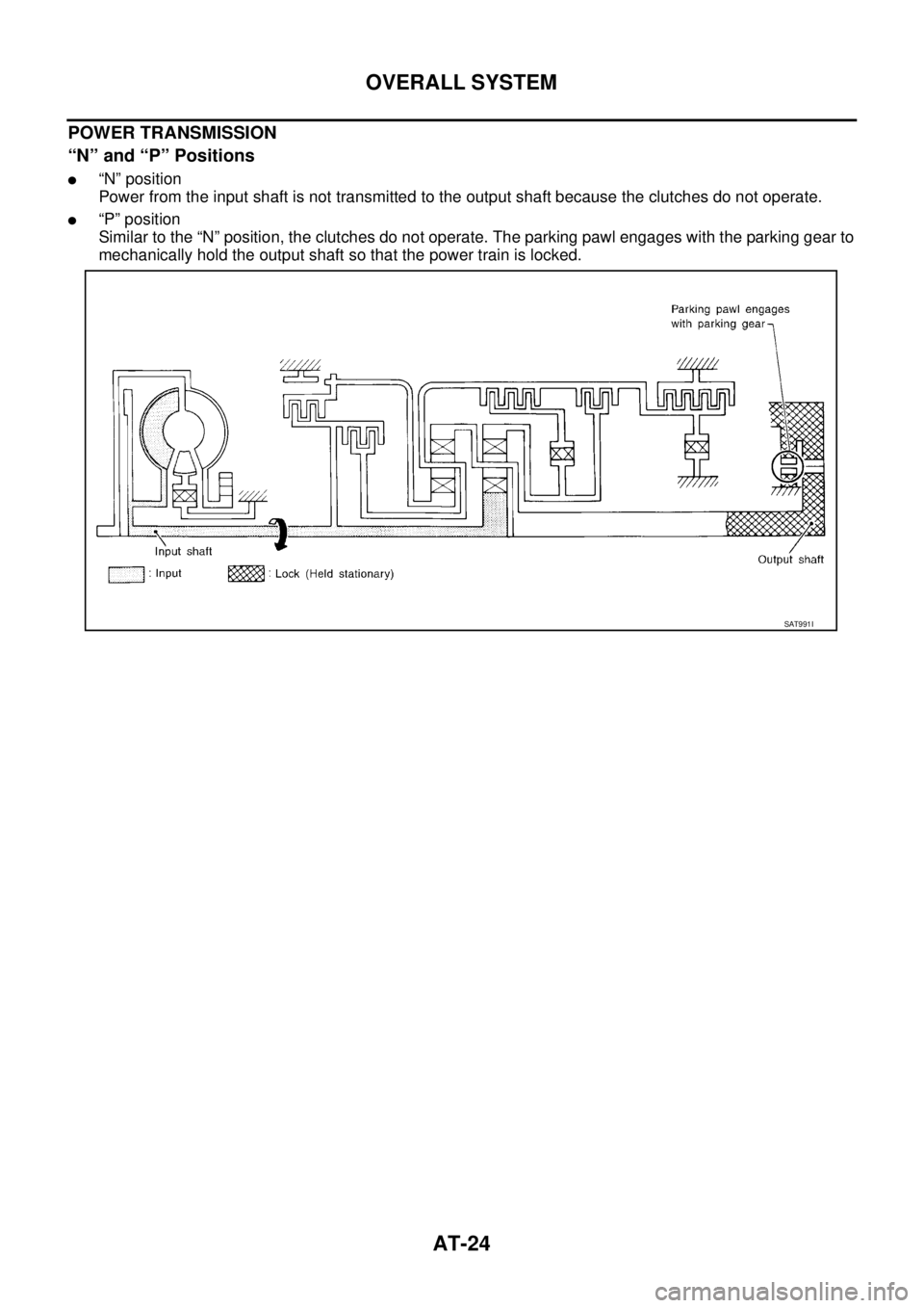
POWER TRANSMISSION
“N” and “P” Positions
�“N” position
Power from the input shaft is not transmitted to the output shaft because the clutches do not operate.
�“P” position
Similar to the “N” position, the clutches do not operate. The parking pawl engages with the parking gear to
mechanically hold the output shaft so that the power train is locked.
SAT991I
Page 2061 of 4179
OVERALL SYSTEM
AT-25
D
E
F
G
H
I
J
K
L
MA
B
AT
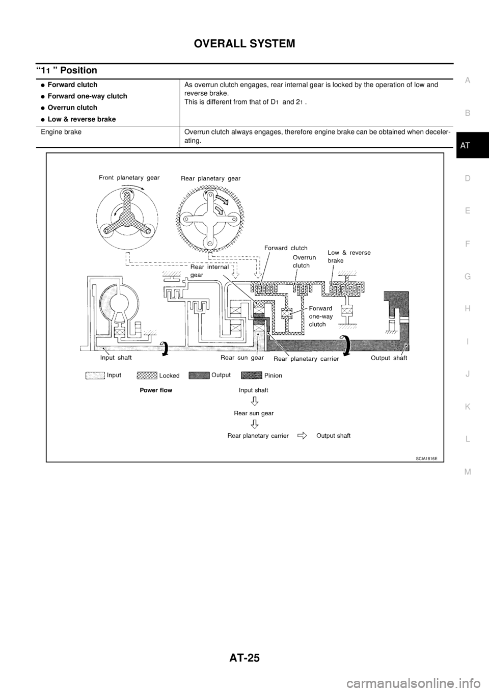
“11 ” Position
�Forward clutch
�Forward one-way clutch
�Overrun clutch
�Low & reverse brakeAs overrun clutch engages, rear internal gear is locked by the operation of low and
reverse brake.
This is different from that of D
1 and 21 .
Engine brake Overrun clutch always engages, therefore engine brake can be obtained when deceler-
ating.
SCIA1816E
Page 2062 of 4179
AT-26
OVERALL SYSTEM
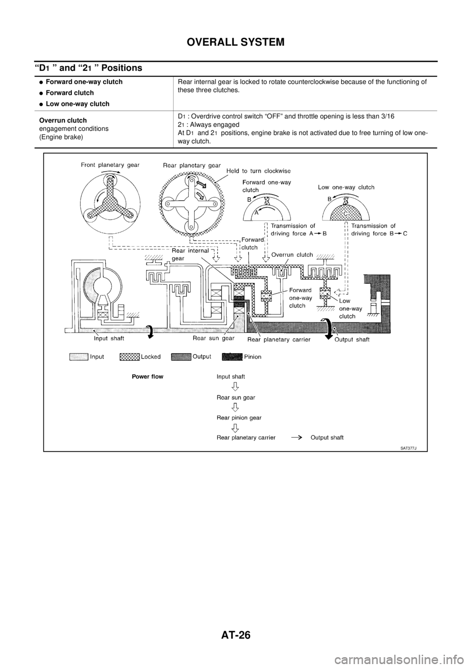
“D1 ” and “21 ” Positions
�Forward one-way clutch
�Forward clutch
�Low one-way clutchRear internal gear is locked to rotate counterclockwise because of the functioning of
these three clutches.
Overrun clutch
engagement conditions
(Engine brake)D
1 : Overdrive control switch “OFF” and throttle opening is less than 3/16
2
1 : Always engaged
At D
1 and 21 positions, engine brake is not activated due to free turning of low one-
way clutch.
SAT377J
Page 2067 of 4179

OVERALL SYSTEM
AT-31
D
E
F
G
H
I
J
K
L
MA
B
AT
TCM FunctionECS004QE
The function of the TCM is to:
�Receive input signals sent from various switches and sensors.
�Determine required line pressure, shifting point, lock-up operation, and engine brake operation.
�Send required output signals to the respective solenoids.
CONTROL SYSTEM OUTLINE
The automatic transaxle senses vehicle operating conditions through various switches and sensors. It always
controls the optimum shift position and reduces shifting and lock-up shocks.
CONTROL SYSTEM
SWITCHES & SENSORS
�TCM
�ACTUATORS
PNP switch
Accelerator pedal position (APP)
sensor
Closed throttle position signal
Wide open throttle position signal
Engine speed signal
A/T fluid temperature sensor
Revolution sensor
Vehicle speed sensor
Overdrive control switch signal
Stop lamp switch signalShift control
Line pressure control
Lock-up control
Overrun clutch control
Timing control
Fail-safe control
Self-diagnosis
CONSULT-II communication line
control
CAN systemShift solenoid valve A
Shift solenoid valve B
Overrun clutch solenoid valve
Torque converter clutch solenoid
valve
Line pressure solenoid valve
O/D OFF indicator lamp
SCIA4505E
Page 2070 of 4179

*2: Spare for accelerator pedal position signal
*3: If these input and output sign")
AT-34
OVERALL SYSTEM
Input/Output Signal of TCMECS00CTC
*1: Spare for vehicle speed sensor·A/T (revolution sensor)
*2: Spare for accelerator pedal position signal
*3: If these input and output signals are different, the TCM triggers the fail-safe function.
*4: Used as a condition for starting self-diagnostics; if self-diagnostics are not started, it is judged that there is some kind of error.
*5: Input by CAN communications.
*6: Output by CAN communications.
Line Pressure ControlECS004QF
�TCM has various line pressure control characteristics to match the driving conditions.
�An ON-OFF duty signal is sent to the line pressure solenoid valve based on TCM characteristics.
�Hydraulic pressure on the clutch and brake is electronically controlled through the line pressure solenoid
valve to accommodate engine torque. This results in smooth shift operation.
NORMAL CONTROL
The line pressure to throttle opening characteristics is set for suitable
clutch operation.
Control itemLine
pressure
controlVehicle
speed
controlShift
controlLock-up
controlEngine
brake
controlFail-safe
function
(*3)Self-diag-
nostics
function
InputAccelerator pedal position signalXXXXXXX
Vehicle speed sensor A/T
(Revolution sensor)XXXX XX
Vehicle speed sensor MTR
(*1)XXXX X
Closed throttle position signal
(*5)(*2) X (*2) X X (*4) X
Wide open throttle position signal
(*5)(*2) X (*2) X (*4) X
Engine speed signal X X
PNP switch XXXXXX(*4) X
Stop lamp switch signal
(*5)XXX(*4) X
A/T fluid temperature sensors X X X X X
TCM power supply voltage signal XX
Out-
putShift solenoid valve A/B X X X
Line pressure solenoid X X X
Torque converter clutch solenoid
valveXXX
Overrun clutch solenoid valve X X X X
O/D OFF indicator lamp
(*6)X
SAT003J
Page 2072 of 4179

AT-36
OVERALL SYSTEM
CONTROL OF SHIFT SOLENOID VALVES A AND B
The TCM activates shift solenoid valves A and B according to sig-
nals from the throttle position sensor and revolution sensor to select
the optimum gear position on the basis of the shift schedule memo-
rized in the TCM.
The shift solenoid valve performs simple ON-OFF operation. When
set to “ON”, the drain circuit closes and pilot pressure is applied to
the shift valve.
RELATION BETWEEN SHIFT SOLENOID VALVES A AND B GEAR POSITIONS
CONTROL OF SHIFT VALVES A AND B
Pilot pressure generated by the operation of shift solenoid valves A and B is applied to the end face of shift
valves A and B.
The drawing above shows the operation of shift valve B. When the shift solenoid valve is “ON”, pilot pressure
applied to the end face of the shift valve overcomes spring force, moving the valve upward.
Lock-up ControlECS00CTE
The torque converter clutch piston in the torque converter is locked to eliminate torque converter slip to
increase power transmission efficiency. The solenoid valve is controlled by an ON-OFF duty signal sent from
the TCM. The signal is converted to an oil pressure signal which controls the torque converter clutch piston.
CONDITIONS FOR LOCK-UP OPERATION
When vehicle is driven in 3rd and 4th gear position, vehicle speed and throttle opening are detected. If the
detected values fall within the lock-up zone memorized in the TCM, lock-up is performed.
SAT008J
Shift solenoid valveGear position
D1 , 21 , 11D2 , 22 , 12D3D4 (OD) N-P
A ON (Closed) OFF (Open) OFF (Open) ON (Closed) ON (Closed)
B ON (Closed) ON (Closed) OFF (Open) OFF (Open) ON (Closed)
SAT009J
Overdrive control switch ON OFF
Selector lever “D” position
Gear position D
4D3
Vehicle speed sensor More than set value
Throttle position sensor Less than set opening
Closed throttle position switch OFF
A/T fluid temperature sensor More than 40°C (104°F)