2003 NISSAN X-TRAIL timing belt
[x] Cancel search: timing beltPage 383 of 4179
EC-5
C
D
E
F
G
H
I
J
K
L
M
ECA
Diagnostic Procedure ........................................... 382
Component Inspection ......................................... 384
DTC P2122, P2123 APP SENSOR ........................ 386
Component Description ........................................ 386
CONSULT-II Reference Value in Data Monitor Mode
. 386
On Board Diagnosis Logic ................................... 386
DTC Confirmation Procedure ............................... 387
Wiring Diagram .................................................... 388
Diagnostic Procedure ........................................... 390
Component Inspection ......................................... 392
Removal and Installation ...................................... 392
DTC P2127, P2128 APP SENSOR ........................ 393
Component Description ........................................ 393
CONSULT-II Reference Value in Data Monitor Mode
. 393
On Board Diagnosis Logic ................................... 393
DTC Confirmation Procedure ............................... 393
Wiring Diagram .................................................... 395
Diagnostic Procedure ........................................... 397
Component Inspection ......................................... 400
Removal and Installation ...................................... 400
DTC P2135 TP SENSOR ........................................ 401
Component Description ........................................ 401
CONSULT-II Reference Value in Data Monitor Mode
. 401
On Board Diagnosis Logic ................................... 401
DTC Confirmation Procedure ............................... 401
Wiring Diagram .................................................... 403
Diagnostic Procedure ........................................... 405
Component Inspection ......................................... 408
Removal and Installation ...................................... 408
DTC P2138 APP SENSOR ..................................... 409
Component Description ........................................ 409
CONSULT-II Reference Value in Data Monitor Mode
. 409
On Board Diagnosis Logic ................................... 409
DTC Confirmation Procedure ............................... 410
Wiring Diagram ..................................................... 411
Diagnostic Procedure ........................................... 413
Component Inspection ......................................... 416
Removal and Installation ...................................... 416
IGNITION SIGNAL .................................................. 417
Component Description ........................................ 417
Wiring Diagram .................................................... 418
Diagnostic Procedure ........................................... 421
Component Inspection ......................................... 426
Removal and Installation ...................................... 427
INJECTOR CIRCUIT ............................................... 428
Component Description ........................................ 428
CONSULT-II Reference Value in Data Monitor Mode
. 428
Wiring Diagram .................................................... 429
Diagnostic Procedure ........................................... 430
Component Inspection ......................................... 433
Removal and Installation ...................................... 433
VIAS ........................................................................ 434
Description ........................................................... 434
CONSULT-II Reference Value in Data Monitor Mode .435
Wiring Diagram .....................................................436
Diagnostic Procedure ...........................................438
Component Inspection ..........................................441
Removal and Installation ......................................442
FUEL PUMP CIRCUIT ............................................443
Description ............................................................443
CONSULT-II Reference Value in Data Monitor Mode
.443
Wiring Diagram .....................................................444
Diagnostic Procedure ...........................................447
Component Inspection ..........................................450
Removal and Installation ......................................450
REFRIGERANT PRESSURE SENSOR ..................451
Component Description ........................................451
Wiring Diagram .....................................................452
Diagnostic Procedure ...........................................453
Removal and Installation ......................................455
ELECTRICAL LOAD SIGNAL ................................456
CONSULT-II Reference Value in Data Monitor Mode
.456
Wiring Diagram .....................................................457
Diagnostic Procedure ...........................................464
MI & DATA LINK CONNECTORS ...........................469
Wiring Diagram .....................................................469
EVAPORATIVE EMISSION SYSTEM .....................473
Description ............................................................473
Component Inspection ..........................................476
POSITIVE CRANKCASE VENTILATION ...............478
Description ............................................................478
Component Inspection ..........................................478
SERVICE DATA AND SPECIFICATIONS (SDS) ....480
Fuel Pressure .......................................................480
Idle Speed and Ignition Timing .............................480
Calculated Load Value ..........................................480
Mass Air Flow Sensor ...........................................480
Intake Air Temperature Sensor .............................480
Engine Coolant Temperature Sensor ...................480
Heated Oxygen Sensor 1 Heater .........................480
Heated Oxygen sensor 2 Heater ..........................481
Crankshaft Position Sensor (POS) .......................481
Camshaft Position Sensor (PHASE) ....................481
Throttle Control Motor ...........................................481
Injector ..................................................................481
Fuel Pump ............................................................481
QR (WITHOUT EURO-OBD)
INDEX FOR DTC .....................................................482
Alphabetical Index ................................................482
DTC No. Index ......................................................484
PRECAUTIONS ......................................................486
Precautions for Supplemental Restraint System
(SRS) “AIR BAG” and “SEAT BELT PRE-TEN-
SIONER” ...............................................................486
On Board Diagnostic (OBD) System of Engine ....486
Precaution ............................................................486
Wiring Diagrams and Trouble Diagnosis ..............489
Page 387 of 4179
EC-9
C
D
E
F
G
H
I
J
K
L
M
ECA
Wiring Diagram .................................................... 793
Diagnostic Procedure ........................................... 794
Component Inspection ......................................... 796
Removal and Installation ...................................... 797
IGNITION SIGNAL .................................................. 798
Component Description ........................................ 798
Wiring Diagram .................................................... 799
Diagnostic Procedure ........................................... 802
Component Inspection ......................................... 807
Removal and Installation ...................................... 808
EVAP CANISTER PURGE VOLUME CONTROL
SOLENOID VALVE ................................................. 809
Description ........................................................... 809
CONSULT-II Reference Value in Data Monitor Mode
. 809
Wiring Diagram .................................................... 810
Diagnostic Procedure ........................................... 812
Component Inspection ......................................... 815
Removal and Installation ...................................... 815
PNP SWITCH .......................................................... 816
Component Description ........................................ 816
CONSULT-II Reference Value in Data Monitor Mode
. 816
Wiring Diagram .................................................... 817
Diagnostic Procedure ........................................... 818
INJECTOR CIRCUIT ............................................... 820
Component Description ........................................ 820
CONSULT-II Reference Value in Data Monitor Mode
. 820
Wiring Diagram .................................................... 821
Diagnostic Procedure ........................................... 822
Component Inspection ......................................... 825
Removal and Installation ...................................... 825
VIAS ........................................................................ 826
Description ........................................................... 826
CONSULT-II Reference Value in Data Monitor Mode
. 827
Wiring Diagram .................................................... 828
Diagnostic Procedure ........................................... 830
Component Inspection ......................................... 833
Removal and Installation ...................................... 834
FUEL PUMP CIRCUIT ............................................ 835
Description ........................................................... 835
CONSULT-II Reference Value in Data Monitor Mode
. 835
Wiring Diagram .................................................... 836
Diagnostic Procedure ........................................... 839
Component Inspection ......................................... 842
Removal and Installation ...................................... 842
REFRIGERANT PRESSURE SENSOR ................. 843
Component Description ........................................ 843
Wiring Diagram .................................................... 844
Diagnostic Procedure ........................................... 845
Removal and Installation ...................................... 847
ELECTRICAL LOAD SIGNAL ................................ 848
CONSULT-II Reference Value in Data Monitor Mode
. 848
Wiring Diagram .................................................... 849
Diagnostic Procedure ........................................... 856MI & DATA LINK CONNECTORS ...........................861
Wiring Diagram .....................................................861
Wiring Diagram – ..................................................863
EVAPORATIVE EMISSION SYSTEM .....................865
Description ............................................................865
Component Inspection ..........................................868
POSITIVE CRANKCASE VENTILATION ...............870
Description ............................................................870
Component Inspection ..........................................870
SERVICE DATA AND SPECIFICATIONS (SDS) ....872
Fuel Pressure .......................................................872
Idle Speed and Ignition Timing .............................872
Mass Air Flow Sensor ...........................................872
Intake Air Temperature Sensor .............................872
Engine Coolant Temperature Sensor ...................872
Heated Oxygen Sensor 1 Heater .........................872
Heated Oxygen sensor 2 Heater ..........................872
Crankshaft Position Sensor (POS) .......................872
Camshaft Position Sensor (PHASE) ....................873
Throttle Control Motor ...........................................873
Injector ..................................................................873
Fuel Pump ............................................................873
YD (WITH EURO-OBD)
INDEX FOR DTC .....................................................874
Alphabetical Index ................................................874
DTC No. Index ......................................................876
PRECAUTIONS ......................................................878
Precautions for Supplemental Restraint System
(SRS) “AIR BAG” and “SEAT BELT PRE-TEN-
SIONER” ...............................................................878
On Board Diagnostic (OBD) System of Engine ....878
Precautions ...........................................................878
Wiring Diagrams and Trouble Diagnosis ..............881
PREPARATION .......................................................882
Special Service Tools ...........................................882
Commercial Service Tools ....................................882
ENGINE CONTROL SYSTEM ................................883
System Diagram ...................................................883
Vacuum Hose Drawing .........................................884
System Chart ........................................................885
Fuel Injection Control System ...............................885
Fuel Injection Timing Control System ...................887
Air Conditioning Cut Control .................................887
Fuel Cut Control (At No Load & High Engine Speed) .887
Crankcase Ventilation System ..............................888
CAN Communication ............................................888
BASIC SERVICE PROCEDURE .............................890
Fuel Filter ..............................................................890
Fuel Pump Learning Value Clearing .....................890
ON BOARD DIAGNOSTIC (OBD) SYSTEM ..........892
Introduction ...........................................................892
Three Trip Detection Logic and One Trip Detection
Logic .....................................................................892
Emission-related Diagnostic Information ..............892
NATS (Nissan Anti-theft System) .........................896
Malfunction Indicator (MI) .....................................896
OBD System Operation Chart ..............................898
Page 392 of 4179

EC-14 Crankshaft Position Sensor .................................1204
Camshaft Position Sensor ...................................1204
YD (WITHOUT EURO-OBD)
INDEX FOR DTC ....................................................1205
Alphabetical Index ...............................................1205
DTC No. Index .....................................................1206
PRECAUTIONS ......................................................1209
Precautions for Supplemental Restraint System
(SRS) “AIR BAG” and “SEAT BELT PRE-TEN-
SIONER” ..............................................................1209
On Board Diagnostic (OBD) System of Engine ...1209
Precautions ..........................................................1209
Wiring Diagrams and Trouble Diagnosis .............1212
PREPARATION ......................................................1213
Special Service Tools ..........................................1213
Commercial Service Tools ...................................1213
ENGINE CONTROL SYSTEM ...............................1214
System Diagram ..................................................1214
Vacuum Hose Drawing ........................................1215
System Chart .......................................................1216
Fuel Injection Control System ..............................1216
Fuel Injection Timing Control System ..................1218
Air Conditioning Cut Control ................................1218
Fuel Cut Control (At No Load & High Engine Speed) 1218
Crankcase Ventilation System .............................1219
CAN Communication ...........................................1219
BASIC SERVICE PROCEDURE ............................1221
Fuel Filter .............................................................1221
Fuel Pump Learning Value Clearing ....................1221
ON BOARD DIAGNOSTIC (OBD) SYSTEM .........1223
DTC and MI Detection Logic ...............................1223
Diagnostic Trouble Code (DTC) ..........................1223
Freeze Frame Data ..............................................1223
NATS (Nissan Anti-theft System) .........................1224
Malfunction Indicator (MI) ....................................1224
TROUBLE DIAGNOSIS .........................................1227
Trouble Diagnosis Introduction ............................1227
DTC Inspection Priority Chart ..............................1230
Basic Inspection ..................................................1231
Symptom Matrix Chart .........................................1235
Engine Control Component Parts Location .........1239
Circuit Diagram ....................................................1243
ECM Harness Connector Terminal Layout ..........1245
ECM Terminals And Reference Value .................1245
CONSULT-II Function ..........................................1251
CONSULT-II Reference Value in Data Monitor Mode
1257
Major Sensor Reference Graph in Data Monitor
Mode ....................................................................1259
TROUBLE DIAGNOSIS FOR INTERMITTENT INCI-
DENT ......................................................................1260
Description ...........................................................1260
Diagnostic Procedure ..........................................1260
MAIN POWER SUPPLY AND GROUND CIRCUIT 1261
ECM Terminals and Reference Value ..................1261
Wiring Diagram ....................................................1262
Diagnostic Procedure ..........................................1263Component Inspection .........................................1266
Ground Inspection ................................................1267
DTC U1000 CAN COMMUNICATION LINE ...........1268
Description ...........................................................1268
On Board Diagnosis Logic ...................................1268
DTC Confirmation Procedure ...............................1268
Wiring Diagram ....................................................1269
Diagnostic Procedure ...........................................1270
DTC P0016 CKP - CMP CORRELATION ..............1271
On Board Diagnosis Logic ...................................1271
DTC Confirmation Procedure ...............................1271
Diagnostic Procedure ...........................................1271
DTC P0088 FUEL SYSTEM ...................................1273
On Board Diagnosis Logic ...................................1273
DTC Confirmation Procedure ...............................1273
Diagnostic Procedure ...........................................1273
Removal and Installation ......................................1274
DTC P0089 FUEL PUMP .......................................1275
On Board Diagnosis Logic ...................................1275
DTC Confirmation Procedure ...............................1275
Diagnostic Procedure ...........................................1275
Removal and Installation ......................................1276
DTC P0093 FUEL SYSTEM ...................................1277
On Board Diagnosis Logic ...................................1277
DTC Confirmation Procedure ...............................1277
Diagnostic Procedure ...........................................1277
Component Inspection .........................................1278
Removal and Installation ......................................1279
DTC P0102, P0103 MAF SENSOR ........................1280
Component Description .......................................1280
CONSULT-II Reference Value in Data Monitor Mode
1280
ECM Terminals and Reference Value ..................1280
On Board Diagnosis Logic ...................................1280
DTC Confirmation Procedure ...............................1280
Wiring Diagram ....................................................1282
Diagnostic Procedure ...........................................1283
Component Inspection .........................................1285
Removal and Installation ......................................1285
DTC P0112, P0113 IAT SENSOR ...........................1286
Component Description .......................................1286
On Board Diagnosis Logic ...................................1286
DTC Confirmation Procedure ...............................1286
Wiring Diagram ....................................................1287
Diagnostic Procedure ...........................................1288
Component Inspection .........................................1290
Removal and Installation ......................................1290
DTC P0117, P0118 ECT SENSOR .........................1291
Description ...........................................................1291
On Board Diagnosis Logic ...................................1291
DTC Confirmation Procedure ...............................1291
Wiring Diagram ....................................................1293
Diagnostic Procedure ...........................................1294
Component Inspection .........................................1296
Removal and Installation ......................................1296
DTC P0122, P0123 APP SENSOR ........................1297
Description ...........................................................1297
CONSULT-II Reference Value in Data Monitor Mode
1297
Page 3399 of 4179
ATC-3
C
D
E
F
G
H
I
K
L
MA
B
AT C
AMBIENT SENSOR ................................................ 121
Removal and Installation ...................................... 121
REMOVAL ......................................................... 121
INSTALLATION ................................................. 121
IN-VEHICLE SENSOR ............................................ 122
Removal and Installation ...................................... 122
REMOVAL ......................................................... 122
INSTALLATION ................................................. 122
SUNLOAD SENSOR .............................................. 123
Removal and Installation ...................................... 123
REMOVAL ......................................................... 123
INSTALLATION ................................................. 123
INTAKE SENSOR ................................................... 124
Removal and Installation ...................................... 124
REMOVAL ......................................................... 124
INSTALLATION ................................................. 124
BLOWER UNIT ....................................................... 125
Removal and Installation ...................................... 125
REMOVAL ......................................................... 125
INSTALLATION ................................................. 125
Disassembly and Assembly ................................. 126
BLOWER MOTOR .................................................. 127
Removal and Installation ...................................... 127
REMOVAL ......................................................... 127
INSTALLATION ................................................. 127
INTAKE DOOR MOTOR ......................................... 128
Removal and Installation ...................................... 128
REMOVAL ......................................................... 128
INSTALLATION ................................................. 128
FAN CONTROL AMPLIFIER .................................. 129
Removal and Installation ...................................... 129
REMOVAL ......................................................... 129
INSTALLATION ................................................. 129
VENTILATION AIR FILTER .................................... 130
Removal and Installation ...................................... 130
FUNCTION ........................................................ 130
REPLACEMENT TIMING .................................. 130
REPLACEMENT PROCEDURES ..................... 130
HEATER & COOLING UNIT ASSEMBLY .............. 131
Removal and Installation ...................................... 131
REMOVAL ......................................................... 131
INSTALLATION ................................................. 132
Disassembly and Assembly ................................. 132
MODE DOOR MOTOR ........................................... 134
Removal and Installation ...................................... 134
REMOVAL ......................................................... 134
INSTALLATION ................................................. 134
AIR MIX DOOR MOTOR ......................................... 135
Removal and Installation ...................................... 135
REMOVAL ......................................................... 135
INSTALLATION ................................................. 135
HEATER CORE ...................................................... 136
Removal and Installation ...................................... 136
REMOVAL ......................................................... 136
INSTALLATION ................................................. 136
DUCTS AND GRILLES .......................................... 137
Removal and Installation ...................................... 137
REMOVAL ......................................................... 137
INSTALLATION ................................................. 140REFRIGERANT LINES ...........................................141
HFC-134a (R-134a) Service Procedure ...............141
SETTING OF SERVICE TOOLS AND EQUIP-
MENT ................................................................141
Components .........................................................143
WITH GASOLINE ENGINE ...............................143
WITH DIESEL ENGINE .....................................144
Removal and Installation of Compressor ..............144
REMOVAL .........................................................144
INSTALLATION .................................................146
Removal and Installation of Compressor Clutch ..146
REMOVAL .........................................................146
INSTALLATION .................................................150
Removal and Installation of Low-pressure Flexible
Hose .....................................................................153
REMOVAL .........................................................153
INSTALLATION .................................................154
Removal and Installation of High-pressure Flexible
Hose .....................................................................154
REMOVAL .........................................................154
INSTALLATION .................................................155
Removal and Installation of High-pressure Pipe ..155
REMOVAL .........................................................155
INSTALLATION .................................................155
Removal and Installation of Condenser ................155
REMOVAL .........................................................155
INSTALLATION .................................................156
Removal and Installation of Liquid Tank ...............156
REMOVAL .........................................................156
INSTALLATION .................................................157
Removal and Installation of Refrigerant Pressure
Sensor ..................................................................157
REMOVAL .........................................................157
INSTALLATION .................................................157
Removal and Installation of Dual-pressure Switch .158
REMOVAL .........................................................158
INSTALLATION .................................................158
Removal and Installation of Evaporator ................158
REMOVAL .........................................................158
INSTALLATION .................................................159
Removal and Installation of Expansion Valve .......159
REMOVAL .........................................................159
INSTALLATION .................................................159
Checking for Refrigerant Leaks ............................160
Checking System for Leaks Using the Fluorescent
Leak Detector .......................................................160
Dye Injection .........................................................160
Electronic Refrigerant Leak Detector ....................161
PRECAUTIONS FOR HANDLING LEAK
DETECTOR .......................................................161
CHECKING PROCEDURE ...............................161
SERVICE DATA AND SPECIFICATIONS (SDS) ....164
Compressor ..........................................................164
Lubricant ...............................................................164
Refrigerant ............................................................164
Engine Idling Speed .............................................164
Belt Tension ..........................................................164
Page 3560 of 4179
ATC-164
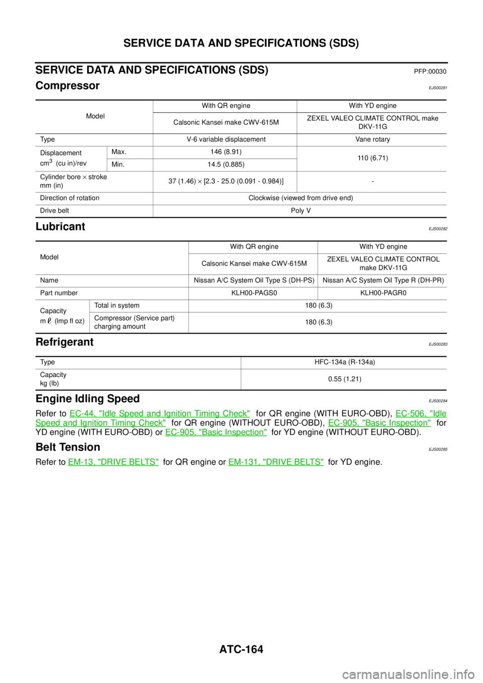
SERVICE DATA AND SPECIFICATIONS (SDS)
SERVICE DATA AND SPECIFICATIONS (SDS)PFP:00030
CompressorEJS00281
LubricantEJS00282
RefrigerantEJS00283
Engine Idling SpeedEJS00284
Refer to EC-44, "Idle Speed and Ignition Timing Check" for QR engine (WITH EURO-OBD), EC-506, "Idle
Speed and Ignition Timing Check" for QR engine (WITHOUT EURO-OBD), EC-905, "Basic Inspection" for
YD engine (WITH EURO-OBD) or EC-905, "
Basic Inspection" for YD engine (WITHOUT EURO-OBD).
Belt TensionEJS00285
Refer to EM-13, "DRIVE BELTS" for QR engine or EM-131, "DRIVE BELTS" for YD engine.
ModelWith QR engine With YD engine
Calsonic Kansei make CWV-615MZEXEL VALEO CLIMATE CONTROL make
DKV-11G
Type V-6 variable displacement Vane rotary
Displacement
cm
3 (cu in)/revMax. 146 (8.91)
110 (6.71)
Min. 14.5 (0.885)
Cylinder bore × stroke
mm (in)37 (1.46) × [2.3 - 25.0 (0.091 - 0.984)] -
Direction of rotation Clockwise (viewed from drive end)
Drive beltPoly V
ModelWith QR engine With YD engine
Calsonic Kansei make CWV-615MZEXEL VALEO CLIMATE CONTROL
make DKV-11G
Name Nissan A/C System Oil Type S (DH-PS) Nissan A/C System Oil Type R (DH-PR)
Part number KLH00-PAGS0 KLH00-PAGR0
Capacity
m (lmp fl oz)Total in system 180 (6.3)
Compressor (Service part)
charging amount180 (6.3)
Ty p eHFC-134a (R-134a)
Capacity
kg (lb)0.55 (1.21)
Page 4175 of 4179
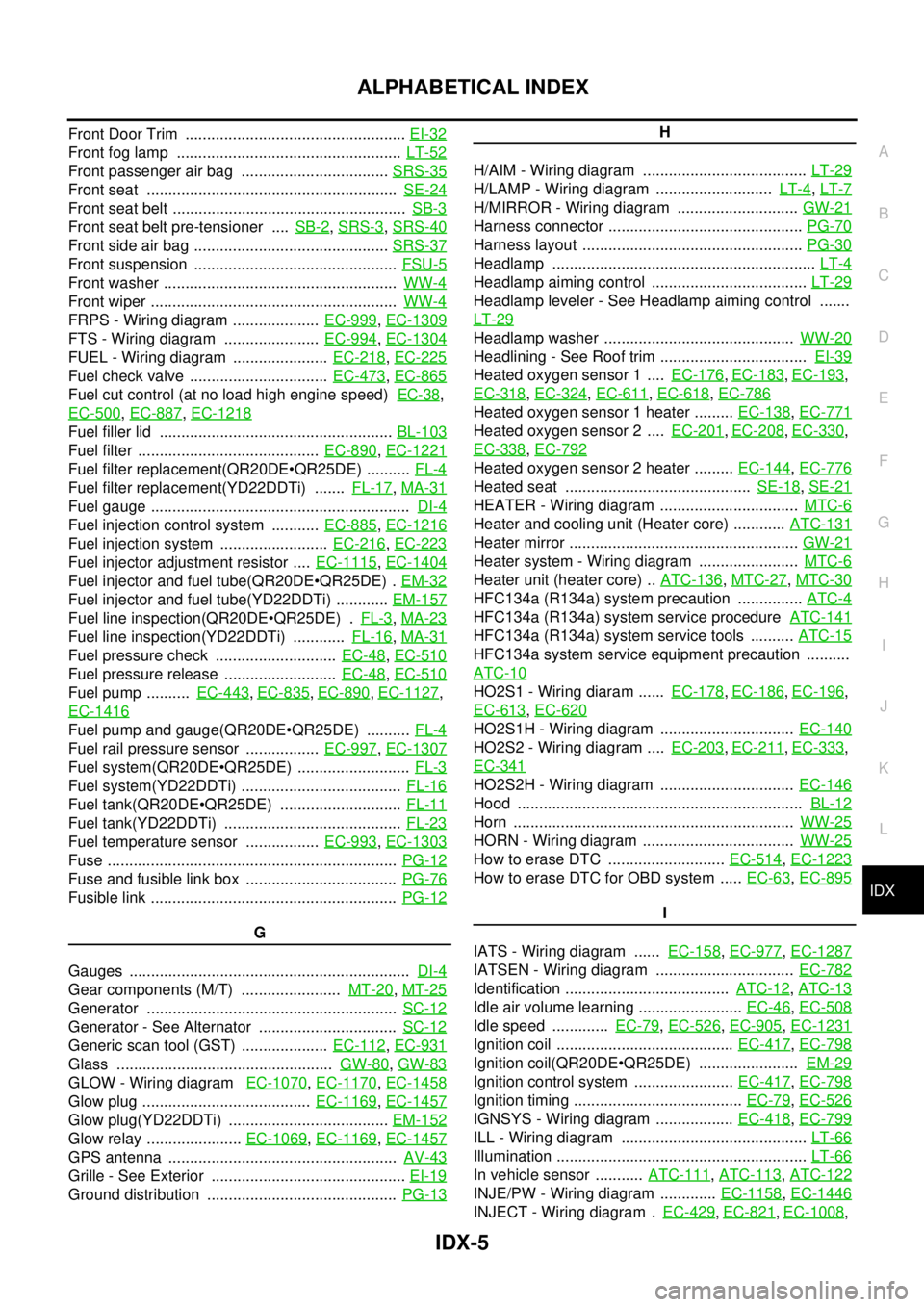
IDX-5
A
C
D
E
F
G
H
I
J
K
L B
IDX
ALPHABETICAL INDEX
Front Door Trim ................................................... EI-32
Front fog lamp .................................................... LT-52
Front passenger air bag .................................. SRS-35
Front seat .......................................................... SE-24
Front seat belt ...................................................... SB-3
Front seat belt pre-tensioner .... SB-2, SRS-3, SRS-40
Front side air bag ............................................. SRS-37
Front suspension ............................................... FSU-5
Front washer ...................................................... WW-4
Front wiper ......................................................... WW-4
FRPS - Wiring diagram .................... EC-999, EC-1309
FTS - Wiring diagram ...................... EC-994, EC-1304
FUEL - Wiring diagram ...................... EC-218, EC-225
Fuel check valve ................................ EC-473, EC-865
Fuel cut control (at no load high engine speed) EC-38,
EC-500
, EC-887, EC-1218
Fuel filler lid ...................................................... BL-103
Fuel filter .......................................... EC-890, EC-1221
Fuel filter replacement(QR20DEQR25DE) .......... FL-4
Fuel filter replacement(YD22DDTi) ....... FL-17, MA-31
Fuel gauge ............................................................ DI-4
Fuel injection control system ........... EC-885, EC-1216
Fuel injection system ......................... EC-216, EC-223
Fuel injector adjustment resistor .... EC-1115, EC-1404
Fuel injector and fuel tube(QR20DEQR25DE) . EM-32
Fuel injector and fuel tube(YD22DDTi) ............ EM-157
Fuel line inspection(QR20DEQR25DE) . FL-3, MA-23
Fuel line inspection(YD22DDTi) ............ FL-16, MA-31
Fuel pressure check ............................ EC-48, EC-510
Fuel pressure release .......................... EC-48, EC-510
Fuel pump .......... EC-443, EC-835, EC-890, EC-1127,
EC-1416
Fuel pump and gauge(QR20DEQR25DE) .......... FL-4
Fuel rail pressure sensor ................. EC-997, EC-1307
Fuel system(QR20DEQR25DE) .......................... FL-3
Fuel system(YD22DDTi) ..................................... FL-16
Fuel tank(QR20DEQR25DE) ............................ FL-11
Fuel tank(YD22DDTi) ......................................... FL-23
Fuel temperature sensor ................. EC-993, EC-1303
Fuse ................................................................... PG-12
Fuse and fusible link box ................................... PG-76
Fusible link ......................................................... PG-12
G
Gauges ................................................................. DI-4
Gear components (M/T) ....................... MT-20, MT-25
Generator .......................................................... SC-12
Generator - See Alternator ................................ SC-12
Generic scan tool (GST) .................... EC-112, EC-931
Glass .................................................. GW-80, GW-83
GLOW - Wiring diagram EC-1070, EC-1170, EC-1458
Glow plug ....................................... EC-1169, EC-1457
Glow plug(YD22DDTi) ..................................... EM-152
Glow relay ...................... EC-1069, EC-1169, EC-1457
GPS antenna ..................................................... AV-43
Grille - See Exterior ............................................. EI-19
Ground distribution ............................................ PG-13
H
H/AIM - Wiring diagram ...................................... LT-29
H/LAMP - Wiring diagram ........................... LT-4, LT-7
H/MIRROR - Wiring diagram ............................ GW-21
Harness connector ............................................. PG-70
Harness layout ................................................... PG-30
Headlamp ............................................................. LT-4
Headlamp aiming control .................................... LT-29
Headlamp leveler - See Headlamp aiming control .......
LT-29
Headlamp washer ............................................ WW-20
Headlining - See Roof trim .................................. EI-39
Heated oxygen sensor 1 .... EC-176, EC-183, EC-193,
EC-318
, EC-324, EC-611, EC-618, EC-786
Heated oxygen sensor 1 heater ......... EC-138, EC-771
Heated oxygen sensor 2 .... EC-201, EC-208, EC-330,
EC-338
, EC-792
Heated oxygen sensor 2 heater ......... EC-144, EC-776
Heated seat ........................................... SE-18, SE-21
HEATER - Wiring diagram ................................ MTC-6
Heater and cooling unit (Heater core) ............ ATC-131
Heater mirror ..................................................... GW-21
Heater system - Wiring diagram ....................... MTC-6
Heater unit (heater core) .. ATC-136, MTC-27, MTC-30
HFC134a (R134a) system precaution ............... ATC-4
HFC134a (R134a) system service procedure ATC-141
HFC134a (R134a) system service tools .......... ATC-15
HFC134a system service equipment precaution ..........
ATC-10
HO2S1 - Wiring diaram ...... EC-178, EC-186, EC-196,
EC-613
, EC-620
HO2S1H - Wiring diagram ............................... EC-140
HO2S2 - Wiring diagram .... EC-203, EC-211, EC-333,
EC-341
HO2S2H - Wiring diagram ............................... EC-146
Hood .................................................................. BL-12
Horn ................................................................. WW-25
HORN - Wiring diagram ................................... WW-25
How to erase DTC ........................... EC-514, EC-1223
How to erase DTC for OBD system ..... EC-63, EC-895
I
IATS - Wiring diagram ...... EC-158
, EC-977, EC-1287
IATSEN - Wiring diagram ................................ EC-782
Identification ...................................... ATC-12, ATC-13
Idle air volume learning ........................ EC-46, EC-508
Idle speed ............. EC-79, EC-526, EC-905, EC-1231
Ignition coil ......................................... EC-417, EC-798
Ignition coil(QR20DEQR25DE) ....................... EM-29
Ignition control system ....................... EC-417, EC-798
Ignition timing ....................................... EC-79, EC-526
IGNSYS - Wiring diagram .................. EC-418, EC-799
ILL - Wiring diagram ........................................... LT-66
Illumination .......................................................... LT-66
In vehicle sensor ........... ATC-111, ATC-113, ATC-122
INJE/PW - Wiring diagram ............. EC-1158, EC-1446
INJECT - Wiring diagram . EC-429, EC-821, EC-1008,