Page 1811 of 4179
DTC P1275 FUEL PUMP
EC-1433
[YD (WITHOUT EURO-OBD)]
C
D
E
F
G
H
I
J
K
L
MA
EC
: Average voltage for pulse signal (Actual pulse signal can be confirmed by oscilloscope.)
On Board Diagnosis LogicEBS0124I
DTC Confirmation ProcedureEBS0124J
NOTE:
If DTC Confirmation Procedure has been previously conducted, always turn ignition switch OFF and wait at
least 10 seconds before conducting the next test.
WITH CONSULT-II
1. Start engine and warm it up to normal operating temperature.
2. Select “DATA MONITOR” mode with CONSULT-II.
3. Keep engine speed more than 2,000 rpm for at least 60 sec-
onds.
4. If DTC is detected, go to EC-1435, "
Diagnostic Procedure" .
DTC No. Trouble diagnosis name DTC detecting condition Possible cause
P1275 Fuel pump exchangeFuel pressure is too much higher than the target
value.
�Harness or connectors
(The fuel pump circuit is open or
shorted.)
�Fuel pump
�Fuel rail pressure sensor
SEF817Y
Page 1813 of 4179
![NISSAN X-TRAIL 2003 Service Repair Manual DTC P1275 FUEL PUMP
EC-1435
[YD (WITHOUT EURO-OBD)]
C
D
E
F
G
H
I
J
K
L
MA
EC
Diagnostic ProcedureEBS0124L
1. CHECK ECM OUTPUT SIGNAL CIRCUIT FOR OPEN AND SHORT
1. Turn ignition switch OFF.
2. Disco](/manual-img/5/57404/w960_57404-1812.png "NISSAN X-TRAIL 2003 Service Repair Manual DTC P1275 FUEL PUMP
EC-1435
[YD (WITHOUT EURO-OBD)]
C
D
E
F
G
H
I
J
K
L
MA
EC
Diagnostic ProcedureEBS0124L
1. CHECK ECM OUTPUT SIGNAL CIRCUIT FOR OPEN AND SHORT
1. Turn ignition switch OFF.
2. Disco")
DTC P1275 FUEL PUMP
EC-1435
[YD (WITHOUT EURO-OBD)]
C
D
E
F
G
H
I
J
K
L
MA
EC
Diagnostic ProcedureEBS0124L
1. CHECK ECM OUTPUT SIGNAL CIRCUIT FOR OPEN AND SHORT
1. Turn ignition switch OFF.
2. Disconnect ECM harness connector and fuel pump harness
connectors.
3. Check harness continuity between ECM terminal 10 and fuel
pump terminal 2.
Refer to Wiring Diagram.
4. Also check harness for short to ground and short to power.
OK or NG
OK >> GO TO 2.
NG >> Repair open circuit or short to ground or short to power
in harness or connectors.
2. CHECK FUEL PUMP GROUND CIRCUIT FOR OPEN AND SHORT
1. Check harness continuity between ECM terminal 29 and fuel pump terminal 1.
Refer to Wiring Diagram.
2. Also check harness for short to ground and short to power.
OK or NG
OK >> GO TO 3.
NG >> Repair open circuit or short to ground or short to power in harness or connectors.
3. CHECK FUEL RAIL PRESSURE SENSOR
Refer to EC-1312, "
Component Inspection" .
OK or NG
OK >> GO TO 4.
NG >> Replace fuel rail.
4. CHECK FUEL PUMP
Refer to EC-1436, "
Component Inspection" .
OK or NG
OK >> GO TO 6.
NG >> GO TO 5.
5. REPLACE FUEL PUMP
1. Replace fuel pump.
2. Perform Fuel Pump Learning Valve Clearing. Refer to EC-1221, "
Fuel Pump Learning Value Clearing" .
>>INSPECTION END
6. CHECK INTERMITTENT INCIDENT
Refer to EC-1260, "
TROUBLE DIAGNOSIS FOR INTERMITTENT INCIDENT" .
>>INSPECTION END Continuity should exist.
PBIB1943E
Continuity should exist.
Page 1861 of 4179
![NISSAN X-TRAIL 2003 Service Repair Manual PSP SWITCH
EC-1483
[YD (WITHOUT EURO-OBD)]
C
D
E
F
G
H
I
J
K
L
MA
EC
PSP SWITCHPFP:49761
Component DescriptionEBS0126A
The power steering pressure switch is attached to the power steer-
ing high-pre](/manual-img/5/57404/w960_57404-1860.png "NISSAN X-TRAIL 2003 Service Repair Manual PSP SWITCH
EC-1483
[YD (WITHOUT EURO-OBD)]
C
D
E
F
G
H
I
J
K
L
MA
EC
PSP SWITCHPFP:49761
Component DescriptionEBS0126A
The power steering pressure switch is attached to the power steer-
ing high-pre")
PSP SWITCH
EC-1483
[YD (WITHOUT EURO-OBD)]
C
D
E
F
G
H
I
J
K
L
MA
EC
PSP SWITCHPFP:49761
Component DescriptionEBS0126A
The power steering pressure switch is attached to the power steer-
ing high-pressure tube and detects a power steering load.
When a power steering load is detected, it signals the ECM. The
ECM adjusts the fuel injector pulse width to increase the idle speed
and adjust for the increased load.
CONSULT-II Reference Value in Data Monitor ModeEBS0126B
Specification data are reference values.
ECM Terminals and Reference ValueEBS0126C
Specification data are reference values, and are measured between each terminal and ground.
CAUTION:
Do not use ECM ground terminals when measuring input/output voltage. Doing so may result in dam-
age to the ECM's transistor. Use a ground other than ECM terminals, such as the ground.
PBIB1904E
MONITOR ITEM CONDITION SPECIFICATION
PW/ST SIGNAL
�Engine: After warming up, idle the
engineSteering wheel is in neutral position.
(Forward direction)OFF
Steering wheel is turned. ON
TERMI-
NAL
NO.WIRE
COLORITEM CONDITIONDATA
(DC Voltage)
111 P / BPower steering pressure
switch[Engine is running]
�Steering wheel is being turnedApproximately 0V
[Engine is running]
�Steering wheel is not being turnedBATTERY VOLTAGE
(11 - 14V)
Page 1878 of 4179
![NISSAN X-TRAIL 2003 Service Repair Manual EC-1500
[YD (WITHOUT EURO-OBD)]
SERVICE DATA AND SPECIFICATIONS (SDS)
SERVICE DATA AND SPECIFICATIONS (SDS)PFP:00100
General SpecificationsEBS0126P
Mass Air Flow SensorEBS0126Q
Engine Coolant Temper](/manual-img/5/57404/w960_57404-1877.png "NISSAN X-TRAIL 2003 Service Repair Manual EC-1500
[YD (WITHOUT EURO-OBD)]
SERVICE DATA AND SPECIFICATIONS (SDS)
SERVICE DATA AND SPECIFICATIONS (SDS)PFP:00100
General SpecificationsEBS0126P
Mass Air Flow SensorEBS0126Q
Engine Coolant Temper")
EC-1500
[YD (WITHOUT EURO-OBD)]
SERVICE DATA AND SPECIFICATIONS (SDS)
SERVICE DATA AND SPECIFICATIONS (SDS)PFP:00100
General SpecificationsEBS0126P
Mass Air Flow SensorEBS0126Q
Engine Coolant Temperature SensorEBS0126R
Fuel Rail Pressure SensorEBS0126S
Glow PlugEBS0126T
EGR Volume Control ValveEBS0126U
Crankshaft Position Sensor EBS0126V
Refer to EC-1356, "Component Inspection" .
Camshaft Position Sensor EBS0126W
Refer to EC-1368, "Component Inspection" .
EngineYD22DDTi
Idle speed725 ± 25 rpm
Maximum engine speed 4,900 rpm
Supply voltageBattery voltage (11 - 14V)
Ignition switch ON (Engine stopped.) Approx. 0.4V
Idle (Engine is warmed up to normal operating temperature.) 1.5 - 2.0V
2,000 rpm (Engine is warmed up to normal operating tempera-
ture.)2.2 - 2.7V
Temperature °C (°F)Resistance kΩ
20 (68)2.1 - 2.9
50 (122)0.68 - 1.00
90 (194)0.236 - 0.260
Supply voltageApproximately 5V
Idle (Engine is warmed up to normal operating temperature.) 1.7 - 2.0V
2,000 rpm (Engine is warmed up to normal operating tempera-
ture.)2.0 - 2.3V
Resistance [at 25°C (77°F)] Ω Approximately 0.8
Resistance [at 25°C (77°F)] Ω13 - 17
Page 1881 of 4179
![NISSAN X-TRAIL 2003 Service Repair Manual FUEL SYSTEM
FL-3
[QR]
C
D
E
F
G
H
I
J
K
L
MA
FL
FUEL SYSTEMPFP:17503
Checking Fuel LinesEBS00KOS
Inspect fuel lines, filler cap and tank for improper attachment, leaks,
cracks, damage, loose connect](/manual-img/5/57404/w960_57404-1880.png "NISSAN X-TRAIL 2003 Service Repair Manual FUEL SYSTEM
FL-3
[QR]
C
D
E
F
G
H
I
J
K
L
MA
FL
FUEL SYSTEMPFP:17503
Checking Fuel LinesEBS00KOS
Inspect fuel lines, filler cap and tank for improper attachment, leaks,
cracks, damage, loose connect")
FUEL SYSTEM
FL-3
[QR]
C
D
E
F
G
H
I
J
K
L
MA
FL
FUEL SYSTEMPFP:17503
Checking Fuel LinesEBS00KOS
Inspect fuel lines, filler cap and tank for improper attachment, leaks,
cracks, damage, loose connections, chafing or deterioration.
If necessary, repair or replace damaged parts.
General PrecautionsEBS011T7
WARNING:
When replacing fuel line parts, be sure to observe the following.
�Put a “CAUTION: INFLAMMABLE” sign in the workshop.
�Be sure to work in a well ventilated area and furnish workshop with a CO2 fire extinguisher.
�Do not smoke while servicing fuel system. Keep open flames and sparks away from the work area.
CAUTION:
�Before removing fuel line parts, perform the following procedures:
–Put drained fuel in an explosion-proof container and put the lid on securely. Keep the container in
safe area.
–Release fuel pressure from the fuel lines. Refer to EC-48, "FUEL PRESSURE RELEASE" (WITH
EURO-OBD) or EC-510, "
FUEL PRESSURE RELEASE" (WITHOUT EURO-OBD).
–Disconnect negative battery terminal.
�Always replace O-rings and clamps with new ones.
�Do not kink or twist tubes when they are being installed.
�Do not tighten hose clamps excessively to avoid damaging hoses.
�After connecting fuel tube quick connectors, make sure
quick connectors are secure.
Ensure that connector and resin tube do not contact any
adjacent parts.
�After installing tubes, check if there are no fuel leaks at con-
nections in the following steps.
–Apply fuel pressure to fuel lines with turning ignition switch
“ON” (with engine stopped). Then check for fuel leaks at
connections.
–Start engine and rev it up and check for fuel leaks at con-
nections.
�For servicing “Evaporative Emission System” parts, refer to
EC-473, "
EVAPORATIVE EMISSION SYSTEM" (WITH EURO-
ODB) or EC-865, "
EVAPORATIVE EMISSION SYSTEM"
(WITHOUT EURO-OBD).
SMA803A
SBIA0504E
Page 1882 of 4179
![NISSAN X-TRAIL 2003 Service Repair Manual FL-4
[QR]
FUEL LEVEL SENSOR UNIT, FUEL FILTER AND FUEL PUMP ASSEMBLY
FUEL LEVEL SENSOR UNIT, FUEL FILTER AND FUEL PUMP ASSEMBLYPFP:17042
Removal and InstallationEBS00KOU
REMOVAL
WARNING:
Be sure to](/manual-img/5/57404/w960_57404-1881.png "NISSAN X-TRAIL 2003 Service Repair Manual FL-4
[QR]
FUEL LEVEL SENSOR UNIT, FUEL FILTER AND FUEL PUMP ASSEMBLY
FUEL LEVEL SENSOR UNIT, FUEL FILTER AND FUEL PUMP ASSEMBLYPFP:17042
Removal and InstallationEBS00KOU
REMOVAL
WARNING:
Be sure to")
FL-4
[QR]
FUEL LEVEL SENSOR UNIT, FUEL FILTER AND FUEL PUMP ASSEMBLY
FUEL LEVEL SENSOR UNIT, FUEL FILTER AND FUEL PUMP ASSEMBLYPFP:17042
Removal and InstallationEBS00KOU
REMOVAL
WARNING:
Be sure to read “General Precautions” when working on the fuel system. Refer to FL-3, "
General Pre-
cautions" .
1. Check fuel level on fuel gauge. If gauge indicates more than the
level as shown in the figure (full or almost full), drain fuel from
fuel tank until gauge indicates level as shown in the figure or
below.
NOTE:
Fuel will be spilled when removing main and sub fuel level sen-
sor units for the top of the fuel is above the main and sub fuel
level sensor units installation surface.
�As a guide, fuel level becomes the position as shown in the
figure or below when approximately 15 (13-1/4 Imp qt) of
fuel are drained from fuel tank.
�In case fuel pump does not operate, perform the following
procedure.
a. Insert fuel tube of less than 25 mm (0.98 in) in diameter into fuel filler tube through fuel filler opening to
draw fuel from fuel filler tube.
b. Disconnect fuel filler hose from fuel filler tube. Refer to FL-11, "
FUEL TANK" .
c. Insert fuel tube into fuel tank through fuel filler hose to draw fuel from fuel tank.
2. Release the fuel pressure from the fuel lines. Refer to EC-48, "
FUEL PRESSURE RELEASE" (WITH
EURO-OBD) or EC-510, "
FUEL PRESSURE RELEASE" (WITHOUT EURO-OBD).
3. Open fuel filler lid.
4. Open fuel filler cap and release the pressure inside fuel tank.
5. Lift to hold rear seat cushion up. Refer to SE-31, "
REAR SEAT" .
1. Lock ring 2.Main fuel level sensor unit, fuel filter
and fuel pump assembly3.Jet pump, fuel hose and jet pump
inlet assembly
4. Chamber 5. Seal packing 6. Sub fuel level sensor unit
PBIC2257E
FEL0403D
Page 1886 of 4179
FL-8
[QR]
FUEL LEVEL SENSOR UNIT, FUEL FILTER AND FUEL PUMP ASSEMBLY
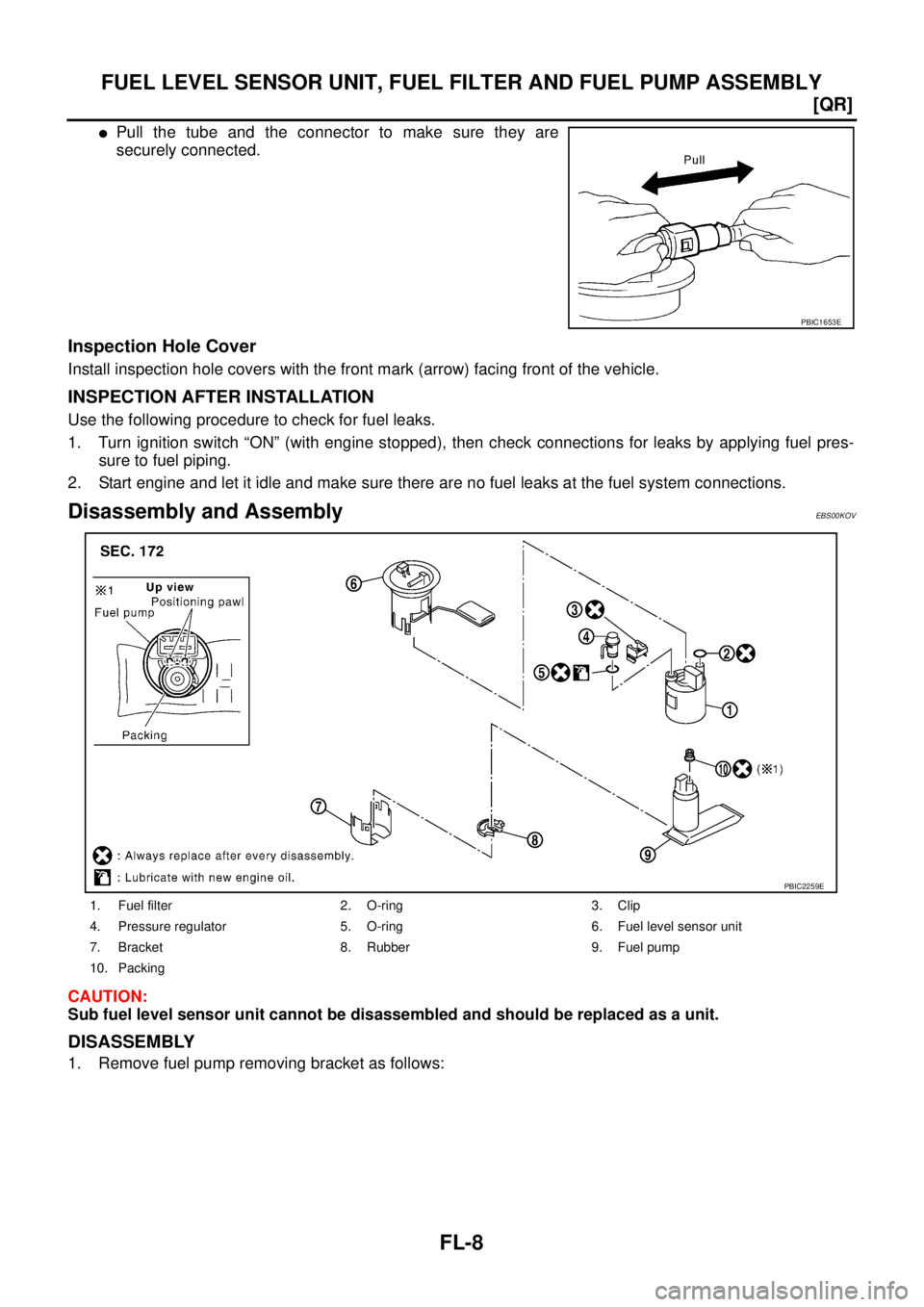
�Pull the tube and the connector to make sure they are
securely connected.
Inspection Hole Cover
Install inspection hole covers with the front mark (arrow) facing front of the vehicle.
INSPECTION AFTER INSTALLATION
Use the following procedure to check for fuel leaks.
1. Turn ignition switch “ON” (with engine stopped), then check connections for leaks by applying fuel pres-
sure to fuel piping.
2. Start engine and let it idle and make sure there are no fuel leaks at the fuel system connections.
Disassembly and AssemblyEBS00KOV
CAUTION:
Sub fuel level sensor unit cannot be disassembled and should be replaced as a unit.
DISASSEMBLY
1. Remove fuel pump removing bracket as follows:
PBIC1653E
1. Fuel filter 2. O-ring 3. Clip
4. Pressure regulator 5. O-ring 6. Fuel level sensor unit
7. Bracket 8. Rubber 9. Fuel pump
10. Packing
PBIC2259E
Page 1887 of 4179
![NISSAN X-TRAIL 2003 Service Repair Manual FUEL LEVEL SENSOR UNIT, FUEL FILTER AND FUEL PUMP ASSEMBLY
FL-9
[QR]
C
D
E
F
G
H
I
J
K
L
MA
FL
a. Using a screwdriver, separate the snap fit portion of bracket in
numerical order as shown in the fig](/manual-img/5/57404/w960_57404-1886.png "NISSAN X-TRAIL 2003 Service Repair Manual FUEL LEVEL SENSOR UNIT, FUEL FILTER AND FUEL PUMP ASSEMBLY
FL-9
[QR]
C
D
E
F
G
H
I
J
K
L
MA
FL
a. Using a screwdriver, separate the snap fit portion of bracket in
numerical order as shown in the fig")
FUEL LEVEL SENSOR UNIT, FUEL FILTER AND FUEL PUMP ASSEMBLY
FL-9
[QR]
C
D
E
F
G
H
I
J
K
L
MA
FL
a. Using a screwdriver, separate the snap fit portion of bracket in
numerical order as shown in the figure.
CAUTION:
Put cloth or similar one on the edge of screwdriver not to
damage the inserted portion.
b. Pull out fuel pump, and disconnect harness connector.
2. Separate fuel filter and fuel level sensor unit as follows:
a. Fit a used O-ring into space between fuel level sensor unit and
fuel filter to release tabs.
NOTE:
For reference when reassembling, put a mating mark on outer
edges of fuel level sensor unit and fuel filter with some means
which cannot be erased by fuel.
b. Insert screwdriver to the gap between fuel filter and fuel level
sensor unit to separate them.
CAUTION:
Put cloth or similar one on the edge of screwdriver not to
damage the inserted portion.
3. Remove pressure regulator from fuel filter as follows:
a. Open and remove the clip.
b. Pull pressure regulator straight out during removal.
CAUTION:
�Avoid impacts such as falling during removal.
�Do not disassemble or adjust.
ASSEMBLY
Note the following, and assemble in the reverse order of disassembly.
�Install fuel filter and fuel pump with the tabs aligned. Make sure a click sound of secure engagement is
heard.
�Securely connect harness connector of fuel pump.
�Install pressure regulator O-ring.
CAUTION:
�When replacing, always use new O-ring.
�Handle it with bare hands. (Do not use gloves.)
�Visually check the O-ring, mounting parts and mating parts for foreign materials and flaws.
�Before installing, apply new engine oil.
�To avid damage, do not apply an excessive force (pulling or starching).
PBIC0242E
PBIC0243E
PBIC0244E
![NISSAN X-TRAIL 2003 Service Repair Manual DTC P1275 FUEL PUMP
EC-1433
[YD (WITHOUT EURO-OBD)]
C
D
E
F
G
H
I
J
K
L
MA
EC
: Average voltage for pulse signal (Actual pulse signal can be confirmed by oscilloscope.)
On Board Diagnosis LogicEBS01](/manual-img/5/57404/w960_57404-1810.png "NISSAN X-TRAIL 2003 Service Repair Manual DTC P1275 FUEL PUMP
EC-1433
[YD (WITHOUT EURO-OBD)]
C
D
E
F
G
H
I
J
K
L
MA
EC
: Average voltage for pulse signal (Actual pulse signal can be confirmed by oscilloscope.)
On Board Diagnosis LogicEBS01")