Page 183 of 4179
![NISSAN X-TRAIL 2003 Service Repair Manual DRIVE BELTS
EM-131
[YD22DDTi]
C
D
E
F
G
H
I
J
K
L
MA
EM
DRIVE BELTSPFP:02117
Checking Drive BeltsEBS00LRA
�Before inspecting engine, make sure engine has cooled down;
wait approximately 30 minutes a](/manual-img/5/57404/w960_57404-182.png "NISSAN X-TRAIL 2003 Service Repair Manual DRIVE BELTS
EM-131
[YD22DDTi]
C
D
E
F
G
H
I
J
K
L
MA
EM
DRIVE BELTSPFP:02117
Checking Drive BeltsEBS00LRA
�Before inspecting engine, make sure engine has cooled down;
wait approximately 30 minutes a")
DRIVE BELTS
EM-131
[YD22DDTi]
C
D
E
F
G
H
I
J
K
L
MA
EM
DRIVE BELTSPFP:02117
Checking Drive BeltsEBS00LRA
�Before inspecting engine, make sure engine has cooled down;
wait approximately 30 minutes after engine has been stopped.
�Visually inspect all belts for wear, damage or cracks on contact-
ing surfaces and edge areas.
�When measuring deflection, apply 98 N (10 kg, 22 lb) at the
marked point ( ).
CAUTION:
�When checking belt deflection immediately after installa-
tion, first adjust it to the specified value. Then, after turn-
ing crankshaft two turns or more, re-adjust to the
specified value to avoid variation in deflection between
pulleys.
�Tighten idler pulley lock nut by hand and measure deflection without looseness.
Belt Deflection:
*: When engine is cold.
Tension AdjustmentEBS00LRB
�Adjust belts with the parts shown below.
CAUTION:
�When a new belt is installed as a replacement, adjust it to the specified value under “New” value
because of insufficient adaptability with pulley grooves.
�If the belt deflection of the current belt is out of the “Limit for re-adjusting”, adjust to the
“Adjusted” value.
�When checking belt deflection immediately after installation, first adjust it to the specified value.
Then, after turning crankshaft two turns or more, re-adjust it to the specified value to avoid vari-
ation in deflection between pulleys.
�Make sure the belts are fully fitted into the pulley grooves during installation.
�Handle with care to avoid smearing the belts with engine oil or engine coolant.
�Do not twist or bend the belts with strong force.
PBIC1251E
Applied beltBelt deflection with 98 N (10 kg, 22 lb) force applied* mm (in)
New Adjusted Limit for re-adjusting
A/C compressor belt 4 - 5 (0.16 - 0.20) 6 - 7 (0.24 - 0.28) 8.5 (0.335)
Alternator and water pump belt 9.0 - 10.5 (0.354 - 0.413) 11.0 - 12.5 (0.433 - 0.492) 16.5 (0.650)
Applied belt Belt adjustment method
A/C compressor belt Adjusting bolt on idler pulley
Alternator and water pump belt Adjusting bolt on alternator
Page 184 of 4179
![NISSAN X-TRAIL 2003 Service Repair Manual EM-132
[YD22DDTi]
DRIVE BELTS
A/C COMPRESSOR BELT
1. Remove RH engine undercover.
2. Loosen idler pulley lock nut (A).
3. Turn adjusting bolt (B) to adjust. Refer to EM-131, "
Checking
Drive Belts"](/manual-img/5/57404/w960_57404-183.png "NISSAN X-TRAIL 2003 Service Repair Manual EM-132
[YD22DDTi]
DRIVE BELTS
A/C COMPRESSOR BELT
1. Remove RH engine undercover.
2. Loosen idler pulley lock nut (A).
3. Turn adjusting bolt (B) to adjust. Refer to EM-131, \"
Checking
Drive Belts\"")
EM-132
[YD22DDTi]
DRIVE BELTS
A/C COMPRESSOR BELT
1. Remove RH engine undercover.
2. Loosen idler pulley lock nut (A).
3. Turn adjusting bolt (B) to adjust. Refer to EM-131, "
Checking
Drive Belts" .
4. Tighten lock nut (A).
ALTERNATOR AND WATER PUMP BELT
1. Loosen adjusting lock nut (C).
2. Loosen alternator fixing bolts (D) (each on front and rear).
3. Turn adjusting bolt (E) to adjust. Refer to EM-131, "
Tension Adjustment" .
4. Tighten nut (C) and bolt (D) in this order.
Removal and InstallationEBS00LRC
REMOVAL
1. Loosen each belt. Refer to EM-131, "Tension Adjustment" .
2. Remove A/C compressor belt. Refer to EM-132, "
A/C COMPRESSOR BELT" .
3. Remove alternator and water pump belt. Refer to EM-132, "
ALTERNATOR AND WATER PUMP BELT" .
INSTALLATION
1. Install each belt on pulley in the reverse order of removal.
2. Adjust belt tension. Refer to EM-131, "
Tension Adjustment" .
3. Tighten nuts and bolts provided for adjustment to the specified torque.
4. Make sure again that each belt tension is as specified.Nut A:
: 31 - 39 N·m (3.1 - 4.0 kg-m, 23 - 28 ft-lb)
PBIC1252E
Nut C:
: 19 - 24 N·m (1.9 - 2.5 kg-m, 14 - 18 ft-lb)
Bolt D:
: 44 - 57 N·m (4.4 - 5.9 kg-m, 32 - 42 ft-lb)
Page 188 of 4179
EM-136
[YD22DDTi]
INTAKE MANIFOLD
INTAKE MANIFOLDPFP:14003
Removal and InstallationEBS00LRF
REMOVAL
WARNING:
To avoid the danger of being scalded, do not drain engine coolant when engine is hot.
1. Drain engine coolant. Refer to CO-31, "
Changing Engine Coolant" .
2. Remove air duct. Refer to EM-133, "
Removal and Installation" .
3. Remove charge air cooler. Refer to EM-135, "
Removal and Installation" .
4. Remove air inlet pipes. Refer to EM-141, "
Removal and Installation" .
5. Remove exhaust manifold insulator. Refer to EM-141, "
EXHAUST MANIFOLD AND TURBOCHARGER" .
1. Fuel gallery 2. Water hose 3. Air relief plug
4. Copper washer 5. Gasket 6. EGR passage
7. EGR volume control valve 8. Bracket 9. Washer
10. Water pipe 11. O-ring 12. EGR cooler
13. Exhaust manifold 14. Intake manifold 15. Cylinder head
16. Heater hose 17. Spill hose
PBIC2020E
Page 189 of 4179
![NISSAN X-TRAIL 2003 Service Repair Manual INTAKE MANIFOLD
EM-137
[YD22DDTi]
C
D
E
F
G
H
I
J
K
L
MA
EM
6. Disconnect EGR volume control valve water hoses and wiring harness.
7. Disconnect heater hose.
8. Remove EGR Cooler.
9. Remove injectio](/manual-img/5/57404/w960_57404-188.png "NISSAN X-TRAIL 2003 Service Repair Manual INTAKE MANIFOLD
EM-137
[YD22DDTi]
C
D
E
F
G
H
I
J
K
L
MA
EM
6. Disconnect EGR volume control valve water hoses and wiring harness.
7. Disconnect heater hose.
8. Remove EGR Cooler.
9. Remove injectio")
INTAKE MANIFOLD
EM-137
[YD22DDTi]
C
D
E
F
G
H
I
J
K
L
MA
EM
6. Disconnect EGR volume control valve water hoses and wiring harness.
7. Disconnect heater hose.
8. Remove EGR Cooler.
9. Remove injection tube center. Refer to EM-157, "
Removal and Installation" .
CAUTION:
Be careful not to spill fuel in the engine component.
10. Remove water pipe.
11. Remove fuel hoses and fuel gallery.
�To prevent fuel from flowing out, plug the opening of the hose with plug after disconnection.
CAUTION:
Be careful not to spill fuel in the engine component.
12. Loosen bolts and nuts in reverse order of that shown in the fig-
ure, and remove intake manifold.
CAUTION:
Cover engine openings to avoid entry of foreign materials.
13. Remove EGR volume control valve from intake manifold.
INSPECTION AFTER REMOVAL
Surface Distortion
�Check distortion on the mounting surface with a straightedge
and feeler gauge.
�If it exceeds the limit, replace intake manifold.
INSTALLATION
Following instructions below, install in the reverse order of removal.
1. Install EGR volume control valve.
�Handle with care avoiding any shocks.
�Do not disassemble.
2. Install intake manifold.
�Tighten fixing bolts and nuts in numerical order as shown in the figure.
�When stud bolts come off, install with the following torque.
PBIC0676E
Limit : 0.1 mm (0.004 in)
PBIC0677E
: 10 - 11 N·m (1.0 - 1.2 kg-m, 87 - 104 in-lb)
Page 190 of 4179
EM-138
[YD22DDTi]
INTAKE MANIFOLD
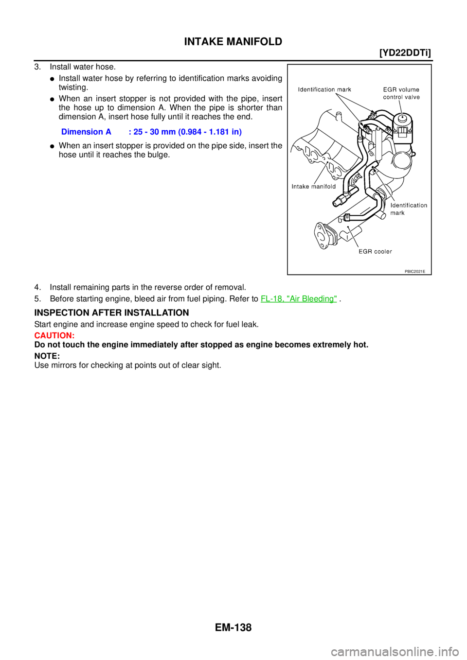
3. Install water hose.
�Install water hose by referring to identification marks avoiding
twisting.
�When an insert stopper is not provided with the pipe, insert
the hose up to dimension A. When the pipe is shorter than
dimension A, insert hose fully until it reaches the end.
�When an insert stopper is provided on the pipe side, insert the
hose until it reaches the bulge.
4. Install remaining parts in the reverse order of removal.
5. Before starting engine, bleed air from fuel piping. Refer to FL-18, "
Air Bleeding" .
INSPECTION AFTER INSTALLATION
Start engine and increase engine speed to check for fuel leak.
CAUTION:
Do not touch the engine immediately after stopped as engine becomes extremely hot.
NOTE:
Use mirrors for checking at points out of clear sight.Dimension A : 25 - 30 mm (0.984 - 1.181 in)
PBIC2021E
Page 191 of 4179
CATALYST
EM-139
[YD22DDTi]
C
D
E
F
G
H
I
J
K
L
MA
EM
CATALYSTPFP:20905
Removal and InstallationEBS00LRG
REMOVAL
1. Remove engine undercover.
2. Drain engine coolant. Refer to CO-31, "
Changing Engine Coolant" .
3. Remove radiator upper and lower hoses. Refer to CO-34, "
RADIATOR" .
4. Remove cooling fan. Refer to CO-36, "
DISASSEMBLY AND ASSEMBLY" .
5. Remove radiator mounting bracket and radiator. Refer to CO-34, "
Removal and Installation" .
6. Remove water inlet pipe. Refer to CO-44, "
THERMOSTAT AND WATER PIPING" .
7. Remove catalyst insulators.
8. Remove exhaust front tube. Refer to EX-2, "
EXHAUST SYSTEM" .
9. Remove catalyst.
CAUTION:
Do not disassemble.
NOTE:
Install two locking pins into both sides of the catalyst. Be careful not to confuse locking pins with insulator
mounting bolts.
1. Catalyst insulator 2. Gasket 3. Catalyst
4. Locking pin 5. Gusset 6. Gasket cap
7. Catalyst rear diffuser
PBIC2312E
Catalyst locking pin : Flange bolt (black)
Page 193 of 4179
![NISSAN X-TRAIL 2003 Service Repair Manual EXHAUST MANIFOLD AND TURBOCHARGER
EM-141
[YD22DDTi]
C
D
E
F
G
H
I
J
K
L
MA
EM
EXHAUST MANIFOLD AND TURBOCHARGERPFP:14004
Removal and InstallationEBS00LRH
REMOVAL
1. Drain engine coolant. Refer to CO](/manual-img/5/57404/w960_57404-192.png "NISSAN X-TRAIL 2003 Service Repair Manual EXHAUST MANIFOLD AND TURBOCHARGER
EM-141
[YD22DDTi]
C
D
E
F
G
H
I
J
K
L
MA
EM
EXHAUST MANIFOLD AND TURBOCHARGERPFP:14004
Removal and InstallationEBS00LRH
REMOVAL
1. Drain engine coolant. Refer to CO")
EXHAUST MANIFOLD AND TURBOCHARGER
EM-141
[YD22DDTi]
C
D
E
F
G
H
I
J
K
L
MA
EM
EXHAUST MANIFOLD AND TURBOCHARGERPFP:14004
Removal and InstallationEBS00LRH
REMOVAL
1. Drain engine coolant. Refer to CO-31, "Changing Engine Coolant" .
2. Remove charge air cooler. Refer to EM-135, "
Removal and Installation" .
3. Remove air duct. Refer to EM-133, "
Removal and Installation" .
4. Remove air inlet pipe.
5. Remove engine undercover.
6. Remove radiator upper and lower hoses. Refer to CO-34, "
RADIATOR" .
7. Remove cooling fan. Refer to CO-36, "
DISASSEMBLY AND ASSEMBLY" .
8. Remove radiator mounting bracket and radiator. Refer to CO-34, "
Removal and Installation" .
9. Remove water inlet pipe. Refer to CO-44, "
THERMOSTAT AND WATER PIPING" .
10. Remove catalyst. Refer to EM-139, "
Removal and Installation" .
11. Remove exhaust manifold insulator.
12. Remove turbocharger insulator.
13. Remove oil feed tube and oil return tube.
1. EGR volume control valve 2. Gasket 3. EGR cooler
4. Air inlet pipe 5.Exhaust manifold and turbocharger
assembly6. Oil feed tube and oil return tube
7. Oil return hose 8. Copper washer 9. Eye-bolt
10. Turbocharger insulator 11. Exhaust manifold insulator 12. Air inlet pipe
PBIC2022E
Page 194 of 4179
![NISSAN X-TRAIL 2003 Service Repair Manual EM-142
[YD22DDTi]
EXHAUST MANIFOLD AND TURBOCHARGER
14. Loosen exhaust manifold mounting nuts in reverse order in the
figure.
15. Rotate exhaust manifold and turbocharger assembly so that the rear s](/manual-img/5/57404/w960_57404-193.png "NISSAN X-TRAIL 2003 Service Repair Manual EM-142
[YD22DDTi]
EXHAUST MANIFOLD AND TURBOCHARGER
14. Loosen exhaust manifold mounting nuts in reverse order in the
figure.
15. Rotate exhaust manifold and turbocharger assembly so that the rear s")
EM-142
[YD22DDTi]
EXHAUST MANIFOLD AND TURBOCHARGER
14. Loosen exhaust manifold mounting nuts in reverse order in the
figure.
15. Rotate exhaust manifold and turbocharger assembly so that the rear side (EGR cooler mounting side)
faces upward. And then pull out the assembly from between the engine and the A/C piping.
CAUTION:
Be careful not to deform each turbocharger piping when pulling out the assembly.
INSTALLATION
�When a stud bolt is pulled out, tighten it to the following torque:
�Tighten the exhaust manifold mounting nuts in the following procedure:
1. Install gasket so that the alignment protrusion faces the No. 4 port. Refer to EM-141, "
Removal and Instal-
lation" .
2. Tighten the nuts in order specified in the figure.
3. Re-tighten the nuts 1 to 4.
4. Install in the reverse order of removal.
INSPECTION AFTER INSTALLATION
Start engine and raise engine speed to check no exhaust gas and engine oil leaks.
JEM266G
: 12.7 - 16.7 N·m (1.3 - 1.7 kg-m, 9 - 12 ft-lb)
JEM266G
![NISSAN X-TRAIL 2003 Service Repair Manual EM-136
[YD22DDTi]
INTAKE MANIFOLD
INTAKE MANIFOLDPFP:14003
Removal and InstallationEBS00LRF
REMOVAL
WARNING:
To avoid the danger of being scalded, do not drain engine coolant when engine is hot.
1.](/manual-img/5/57404/w960_57404-187.png "NISSAN X-TRAIL 2003 Service Repair Manual EM-136
[YD22DDTi]
INTAKE MANIFOLD
INTAKE MANIFOLDPFP:14003
Removal and InstallationEBS00LRF
REMOVAL
WARNING:
To avoid the danger of being scalded, do not drain engine coolant when engine is hot.
1.")
![NISSAN X-TRAIL 2003 Service Repair Manual CATALYST
EM-139
[YD22DDTi]
C
D
E
F
G
H
I
J
K
L
MA
EM
CATALYSTPFP:20905
Removal and InstallationEBS00LRG
REMOVAL
1. Remove engine undercover.
2. Drain engine coolant. Refer to CO-31, "
Changing Engin](/manual-img/5/57404/w960_57404-190.png "NISSAN X-TRAIL 2003 Service Repair Manual CATALYST
EM-139
[YD22DDTi]
C
D
E
F
G
H
I
J
K
L
MA
EM
CATALYSTPFP:20905
Removal and InstallationEBS00LRG
REMOVAL
1. Remove engine undercover.
2. Drain engine coolant. Refer to CO-31, \"
Changing Engin")