Page 197 of 4179
![NISSAN X-TRAIL 2003 Service Repair Manual EXHAUST MANIFOLD AND TURBOCHARGER
EM-145
[YD22DDTi]
C
D
E
F
G
H
I
J
K
L
MA
EM
TURBINE WHEEL
�Make sure that there is no engine oil adhesion.
�Make sure that there is no carbon accumulation.
�Make su](/manual-img/5/57404/w960_57404-196.png "NISSAN X-TRAIL 2003 Service Repair Manual EXHAUST MANIFOLD AND TURBOCHARGER
EM-145
[YD22DDTi]
C
D
E
F
G
H
I
J
K
L
MA
EM
TURBINE WHEEL
�Make sure that there is no engine oil adhesion.
�Make sure that there is no carbon accumulation.
�Make su")
EXHAUST MANIFOLD AND TURBOCHARGER
EM-145
[YD22DDTi]
C
D
E
F
G
H
I
J
K
L
MA
EM
TURBINE WHEEL
�Make sure that there is no engine oil adhesion.
�Make sure that there is no carbon accumulation.
�Make sure that blades of turbine wheel are not bent or broken.
�Make sure that turbine wheel does not interfere with turbine
housing.
COMPRESSOR WHEEL
�Make sure that there is no engine oil adhesion inside the air
inlet.
�Make sure that compressor wheel does not interfere with com-
pressor housing.
�Make sure that compressor wheel is not bent or broken.
TURBOCHARGER BOOST CONTROL ACTUATOR
�Connect the handy vacuum pump to the actuator, and make
sure that the rod strokes smoothly in compliance with the follow-
ing pressure.
�Pressure to be applied at actuator part to move rod end as fol-
lows:
PBIC0729E
PBIC0730E
Standard (Pressure/rod stroke amount):
:–52.0 to –54.6 kPa (–520 to –546 mbar, –390 to –410
mmHg, –15.4 to –16.1 inHg)/0.2 mm (0.0079 in)
: –32.0 to –40.0 kPa (–320 to –400 mbar, –240 to –300
mmHg, –9.45 to –11.8 inHg)/5.0 mm (0.197 in)
PBIC0941E
Page 198 of 4179
![NISSAN X-TRAIL 2003 Service Repair Manual EM-146
[YD22DDTi]
EXHAUST MANIFOLD AND TURBOCHARGER
TROUBLE DIAGNOSIS OF TURBOCHARGER
Preliminary check:
�Make sure that the engine oil level is between MIN and MAX of the oil level gauge. (When eng](/manual-img/5/57404/w960_57404-197.png "NISSAN X-TRAIL 2003 Service Repair Manual EM-146
[YD22DDTi]
EXHAUST MANIFOLD AND TURBOCHARGER
TROUBLE DIAGNOSIS OF TURBOCHARGER
Preliminary check:
�Make sure that the engine oil level is between MIN and MAX of the oil level gauge. (When eng")
EM-146
[YD22DDTi]
EXHAUST MANIFOLD AND TURBOCHARGER
TROUBLE DIAGNOSIS OF TURBOCHARGER
Preliminary check:
�Make sure that the engine oil level is between MIN and MAX of the oil level gauge. (When engine oil
amount is more than MAX, engine oil flows into the inlet duct through blow-by gas passage, and turbo-
charger is misjudged malfunction.)
�Ask the customer if he/she always runs the vehicle in idle engine speed to cool the engine oil down after
driving.
�Replace the turbocharger assembly when any malfunction is found after unit inspections specified in the
table below.
�If no malfunction is found after the unit inspections, judge that the turbocharger body has no malfunction.
Check the other parts again.
A: Large possibility
B: Medium possibility
C: Small possibilityInspection item Inspection resultSymptom
(when each inspection item meets each inspection result)
Engine oil
leakageSmoke NoiseInsufficient power/accel-
eration malfunction
Turbine wheelEngine oil leaks C A C C
Carbon is accumulated C A B B
Friction with housing C B A B
Blades are bent or broken — — A A
Compressor wheelInside the air inlet is seriously con-
taminated by engine oil.BB— —
Friction with housing C B A B
Blades are bent or broken — — A A
After checking both turbine and
compressor, inspect rotor shaft
end play.There is resistance when the rotor
shaft is rotated by your fingertips.—CC B
The rotor shaft sometimes does not
rotate by your fingertips.——— A
There is too much play in the bear-
ing.CCB C
Oil return portCarbon or sludge is accumulated in
the waste oil hole.CAC C
Page 199 of 4179
OIL PAN AND OIL STRAINER
EM-147
[YD22DDTi]
C
D
E
F
G
H
I
J
K
L
MA
EM
OIL PAN AND OIL STRAINERP F P : 1111 0
Removal and InstallationEBS00LRK
REMOVAL
WARNING:
To avoid the danger of being scalded, do not drain engine oil when engine is hot.
1. Remove engine undercover.
2. Drain engine oil. Refer to LU-21, "
Changing Engine Oil" .
3. Remove oil pan lower bolts, Loosen bolts in reverse order of that
shown in the figure.
4. Remove oil pan lower.
1. Rear plate cover 2. Oil pan upper 3. Gasket
4. Oil strainer 5. Oil pan drain plug 6. Drain plug washer
7. Oil pan lower 8. Crankshaft position sensor
PBIC2313E
SBIA0161E
Page 200 of 4179
![NISSAN X-TRAIL 2003 Service Repair Manual EM-148
[YD22DDTi]
OIL PAN AND OIL STRAINER
a. Insert the Seal cutter (special service tool) between oil pan
upper and oil pan lower.
CAUTION:
�Be careful not to damage aluminum mating surface.
�Do n](/manual-img/5/57404/w960_57404-199.png "NISSAN X-TRAIL 2003 Service Repair Manual EM-148
[YD22DDTi]
OIL PAN AND OIL STRAINER
a. Insert the Seal cutter (special service tool) between oil pan
upper and oil pan lower.
CAUTION:
�Be careful not to damage aluminum mating surface.
�Do n")
EM-148
[YD22DDTi]
OIL PAN AND OIL STRAINER
a. Insert the Seal cutter (special service tool) between oil pan
upper and oil pan lower.
CAUTION:
�Be careful not to damage aluminum mating surface.
�Do not insert screwdriver, or oil pan flange will be
deformed.
b. Slide the Seal cutter by tapping on the side of the Seal cutter
with a hammer.
c. Remove oil pan lower.
5. Remove A/C compressor belt. Refer to EM-131, "
Tension Adjustment" .
6. Remove A/C compressor and bracket. Refer to ATC-144, "
Removal and Installation of Compressor" .
7. Remove front exhaust tube and its support. Refer to EX-2, "
EXHAUST SYSTEM" .
8. Remove crankshaft position sensor from transaxle.
CAUTION:
�Avoid impacts such as a dropping.
�Do not disassemble.
�Keep it away from metal particles.
�Do not place sensor close to magnetic materials.
9. Set a suitable transmission jack under transaxle and hoist
engine with engine slinger. Refer to EM-208, "
Removal and
Installation" .
10. Remove center member. Refer to EM-208, "
ENGINE ASSEM-
BLY" .
11. Remove rear plate cover and transaxle joint bolts.
12. Remove catalyst and catalyst rear diffuser. Refer to EM-139,
"Removal and Installation" .
SEM544G
SEM545G
PBIC2277E
JEM553G
Page 202 of 4179
![NISSAN X-TRAIL 2003 Service Repair Manual EM-150
[YD22DDTi]
OIL PAN AND OIL STRAINER
�Tighten bolts in numerical order to the specified torque.
�Bolt dimensions vary depending on the installation location.
Refer to the following and use app](/manual-img/5/57404/w960_57404-201.png "NISSAN X-TRAIL 2003 Service Repair Manual EM-150
[YD22DDTi]
OIL PAN AND OIL STRAINER
�Tighten bolts in numerical order to the specified torque.
�Bolt dimensions vary depending on the installation location.
Refer to the following and use app")
EM-150
[YD22DDTi]
OIL PAN AND OIL STRAINER
�Tighten bolts in numerical order to the specified torque.
�Bolt dimensions vary depending on the installation location.
Refer to the following and use appropriate bolts.
�The shank length under the bolt neck above is the length of
the threaded part (pilot portion not included).
3. Tighten transaxle joint bolts.
4. Install rear plate cover.
5. Install center member. Refer to EM-208, "
ENGINE ASSEMBLY" .
6. Install crankshaft position sensor.
7. Install oil pan lower with the following procedure.
a. Use a scraper to remove old liquid gasket from mating surfaces.
CAUTION:
�Also remove old liquid gasket from mating surface of oil
pan upper.
�Remove old liquid gasket from bolt hole and thread.
b. Apply a continuous bead of liquid gasket with the tube presser
(special service tool: WS39930000) as shown in the figure.
Use Genuine Liquid Gasket or equivalent.
�Be sure liquid gasket is 3.5 to 4.5 mm (0.138 to 0.177 in)
wide.
�Attaching should be done within 5 minutes after coating.M6 x 30 mm (1.18 in) : Bolt No. 15, 16
M8 x 25 mm (0.98 in) : Bolt No. 3, 4, 9, 10
M8 x 60 mm (2.36 in) : Bolt No. 1, 2, 5, 6, 7, 8,
11, 12, 13, 14
SBIA0162E
PBIC2277E
SBIA0163E
SBIA0164E
Page 203 of 4179
OIL PAN AND OIL STRAINER
EM-151
[YD22DDTi]
C
D
E
F
G
H
I
J
K
L
MA
EM
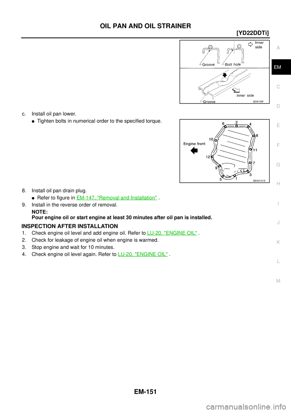
c. Install oil pan lower.
�Tighten bolts in numerical order to the specified torque.
8. Install oil pan drain plug.
�Refer to figure in EM-147, "Removal and Installation" .
9. Install in the reverse order of removal.
NOTE:
Pour engine oil or start engine at least 30 minutes after oil pan is installed.
INSPECTION AFTER INSTALLATION
1. Check engine oil level and add engine oil. Refer to LU-20, "ENGINE OIL" .
2. Check for leakage of engine oil when engine is warmed.
3. Stop engine and wait for 10 minutes.
4. Check engine oil level again. Refer to LU-20, "
ENGINE OIL" .
SEM159F
SBIA0161E
Page 205 of 4179
![NISSAN X-TRAIL 2003 Service Repair Manual VACUUM PUMP
EM-153
[YD22DDTi]
C
D
E
F
G
H
I
J
K
L
MA
EM
VACUUM PUMPPFP:41920
Removal and InstallationEBS00LRM
INSPECTION BEFORE REMOVAL
1. Disconnect vacuum hose, and connect a vacuum gauge via 3-wa](/manual-img/5/57404/w960_57404-204.png "NISSAN X-TRAIL 2003 Service Repair Manual VACUUM PUMP
EM-153
[YD22DDTi]
C
D
E
F
G
H
I
J
K
L
MA
EM
VACUUM PUMPPFP:41920
Removal and InstallationEBS00LRM
INSPECTION BEFORE REMOVAL
1. Disconnect vacuum hose, and connect a vacuum gauge via 3-wa")
VACUUM PUMP
EM-153
[YD22DDTi]
C
D
E
F
G
H
I
J
K
L
MA
EM
VACUUM PUMPPFP:41920
Removal and InstallationEBS00LRM
INSPECTION BEFORE REMOVAL
1. Disconnect vacuum hose, and connect a vacuum gauge via 3-way connector.
�Disconnect point where vacuum from vacuum pump can be measured directly and install 3-way con-
nector.
2. Start engine and measure generated vacuum at idle speed.
�If out of standard, check for air suction in vacuum route, and measure again.
�If still outside of standard, replace vacuum pump.
REMOVAL
1. Drain engine coolant. Refer to CO-31, "Changing Engine Coolant" .
2. Remove air duct and air cleaner case. Refer to EM-133, "
Removal and Installation" .
3. Remove charge air cooler. Refer to EM-135, "
Removal and Installation" .
4. Disconnect harness connector from fuel injector.
5. Remove injection tubes. Refer to EM-157, "
Removal and Installation" .
6. Remove rocker cover. Refer to EM-168, "
Removal and Installation" .
7. Remove spill tube. Refer to EM-157, "
Removal and Installation" .
8. Remove nozzle support from No. 2 cylinder and No. 2 fuel injector. Refer to EM-157, "
Removal and Instal-
lation" . (To fix the hexagonal portion of the camshaft.)
9. Remove air inlet pipes. Refer to EM-141, "
Removal and Installation" .
1.Vacuum pump and cylinder head rear cover
assembly2. O-ring 3. Cylinder head rear cover plate
4. Camshaft position sensor
PBIC2315E
Standard:
– 86.6 to – 101.3 kPa (– 866 to – 1,013 mbar, – 650 to – 760 mmHg, – 25.59 to – 29.92 inHg)
Page 207 of 4179
![NISSAN X-TRAIL 2003 Service Repair Manual VACUUM PUMP
EM-155
[YD22DDTi]
C
D
E
F
G
H
I
J
K
L
MA
EM
5. Install cylinder head rear cover plate.
�Apply a continuous bead of liquid gasket with the tube presser
(special service tool: WS39930000)](/manual-img/5/57404/w960_57404-206.png "NISSAN X-TRAIL 2003 Service Repair Manual VACUUM PUMP
EM-155
[YD22DDTi]
C
D
E
F
G
H
I
J
K
L
MA
EM
5. Install cylinder head rear cover plate.
�Apply a continuous bead of liquid gasket with the tube presser
(special service tool: WS39930000)")
VACUUM PUMP
EM-155
[YD22DDTi]
C
D
E
F
G
H
I
J
K
L
MA
EM
5. Install cylinder head rear cover plate.
�Apply a continuous bead of liquid gasket with the tube presser
(special service tool: WS39930000) to area shown in the fig-
ure.
Use Genuine Liquid Gasket or equivalent.
�Attaching should be done within 5 minutes after coating.
6. Install in reverse order of removal.
�When vacuum hose is connected, insert it securely by at least 15 mm (0.59 in).
CAUTION:
Do not start engine with vacuum circuit being open. If engine is started and vehicle is running while
vacuum pump is open (with vacuum hose disconnected), blow-by flow rate will increase and engine
may be damaged.
INSPECTION AFTER INSTALLATION
Check generated vacuum satisfies the specification at idle speed. Refer to EM-153, "INSPECTION BEFORE
REMOVAL" .
Disassembly and AssemblyEBS00LRN
DISASSEMBLY
1. Push on chain guide lightly so that clearance between drive chain and chain guide part reaches 0 mm (0
in). Then loosen chain guide mounting bolts.
2. Remove drive chain from rear camshaft sprocket and vacuum pump sprocket.
SBIA0169E
1. Rear camshaft sprocket 2. Drive chain 3. Chain guide
4. Cylinder head rear cover 5. Vacuum pump 6. O-ring
PBIC2316E
![NISSAN X-TRAIL 2003 Service Repair Manual OIL PAN AND OIL STRAINER
EM-147
[YD22DDTi]
C
D
E
F
G
H
I
J
K
L
MA
EM
OIL PAN AND OIL STRAINERP F P : 1111 0
Removal and InstallationEBS00LRK
REMOVAL
WARNING:
To avoid the danger of being scalded, do](/manual-img/5/57404/w960_57404-198.png "NISSAN X-TRAIL 2003 Service Repair Manual OIL PAN AND OIL STRAINER
EM-147
[YD22DDTi]
C
D
E
F
G
H
I
J
K
L
MA
EM
OIL PAN AND OIL STRAINERP F P : 1111 0
Removal and InstallationEBS00LRK
REMOVAL
WARNING:
To avoid the danger of being scalded, do")