Page 2088 of 3066
EM-118
[YD22DDTi]
CATALYST
CATALYST
PFP:20905
Removal and InstallationEBS00BOA
REMOVAL
1. Remove engine under cover.
2. Drain engine coolant. Refer toCO-30, "
Changing Engine Coolant".
3. Remove radiator upper hose.
4. Remove radiator fan. Refer toCO-33, "
Removal and Installation".
5. Remove radiator mount bracket and radiator.
6. Remove water inlet pipe.
7. Disconnect exhaust front tube. Refer toEX-2, "
EXHAUST SYSTEM".
8. Remove catalyst.
CAUTION:
Do not disassemble.
Install two locking pins into both sides of the catalyst. Be careful not to confuse locking pins with insulator
mounting bolts.
INSTALLATION
Install in reverse order of removal.
lPushing gussets against the oil pan and the catalyst, temporarily tighten the mounting bolt. And then
tighten it to the specified torque.
SBIA0157E
1. Insulator 2. Catalyst 3. Catalyst rear diffuser
4. Gasket
Catalyst locking pin : Flange bolt (black)
Insulator mounting bolt : Washer bolt (silver or yellow)
Page 2089 of 3066
![NISSAN X-TRAIL 2003 Electronic Repair Manual EXHAUST MANIFOLD AND TURBOCHARGER
EM-119
[YD22DDTi]
C
D
E
F
G
H
I
J
K
L
MA
EM
EXHAUST MANIFOLD AND TURBOCHARGERPFP:14004
Removal and InstallationEBS00BOB
REMOVAL
1. Drain engine coolant. Refer toCO-30 NISSAN X-TRAIL 2003 Electronic Repair Manual EXHAUST MANIFOLD AND TURBOCHARGER
EM-119
[YD22DDTi]
C
D
E
F
G
H
I
J
K
L
MA
EM
EXHAUST MANIFOLD AND TURBOCHARGERPFP:14004
Removal and InstallationEBS00BOB
REMOVAL
1. Drain engine coolant. Refer toCO-30](/manual-img/5/57402/w960_57402-2088.png)
EXHAUST MANIFOLD AND TURBOCHARGER
EM-119
[YD22DDTi]
C
D
E
F
G
H
I
J
K
L
MA
EM
EXHAUST MANIFOLD AND TURBOCHARGERPFP:14004
Removal and InstallationEBS00BOB
REMOVAL
1. Drain engine coolant. Refer toCO-30, "Changing Engine Coolant".
2. Remove charge air cooler. Refer toEM-114, "
Removal and Installation".
3. Remove air duct and air inlet pipe. Refer toEM-112, "
Removal and Installation".
4. Remove engine under cover.
5. Remove radiator upper hose.
6. Remove radiator fan. Refer toCO-34, "
Disassembly and Assembly Radiator Fan".
7. Remove radiator mount bracket and radiator. Refer toCO-33, "
Removal and Installation".
8. Remove water inlet pipe.
9. Disconnect exhaust front tube. Refer toEX-2, "
EXHAUST SYSTEM".
10. Remove catalyst. Refer toEM-118, "
Removal and Installation".
11. Remove exhaust manifold cover.
12. Remove insulator.
13. Each wiring and piping (disconnect/move)
SBIA0158E
1. Electronic EGR control valve 2. Gasket 3. EGR tube
4. Air inlet pipe 5.Exhaust manifold & turbocharger
assembly6. Oil return hose
7. Turbo insulator 8. Exhaust manifold insulator 9. Air inlet pipe
Page 2155 of 3066
![NISSAN X-TRAIL 2003 Electronic Repair Manual ENGINE ASSEMBLY
EM-185
[YD22DDTi]
C
D
E
F
G
H
I
J
K
L
MA
EM
1. Remove engine hood.
2. Drain coolant from radiator drain plug.
3. Remove the following parts.
lLH/RH under cover
lLH/RH front wheel
lBatt NISSAN X-TRAIL 2003 Electronic Repair Manual ENGINE ASSEMBLY
EM-185
[YD22DDTi]
C
D
E
F
G
H
I
J
K
L
MA
EM
1. Remove engine hood.
2. Drain coolant from radiator drain plug.
3. Remove the following parts.
lLH/RH under cover
lLH/RH front wheel
lBatt](/manual-img/5/57402/w960_57402-2154.png)
ENGINE ASSEMBLY
EM-185
[YD22DDTi]
C
D
E
F
G
H
I
J
K
L
MA
EM
1. Remove engine hood.
2. Drain coolant from radiator drain plug.
3. Remove the following parts.
lLH/RH under cover
lLH/RH front wheel
lBattery
lAuxiliary drive belt; Refer toE M - 111 , "Removal and Installation".
lAir duct and air cleaner case assembly; Refer toEM-112, "Removal and Installation".
lAlternator
lRadiator and radiator fan assembly; Refer toCO-33, "Removal and Installation".
lCharge air cooler
4. Disconnect engine room harness from the engine side and set it aside for easier work.
5. Disconnect all the body-side vacuum hoses and air hoses at engine side.
Engine room LH
6. Disconnect fuel feed and return hoses, and plug it to prevent fuel from draining.
7. Disconnect heater hose, and install plug it to prevent engine coolant from draining.
8. Remove clutch operating cylinder from transaxle, and move it aside.
9. Disconnect shift cable from transaxle.
Engine room RH
10. Remove engine coolant reservoir tank.
11. Remove air conditioner compressor with piping connected from engine. Temporarily secure it on body
with a rope to avoid putting load on it.
Vehicle underbody
12. Remove exhaust front tube.
13. Remove propeller shaft.
14. Remove steering shaft from steering gear.
15. Disconnect power steering fluid cooler piping at a point between body and engine.
16. Remove ABS sensor from brake caliper.
17. Remove brake caliper with piping connected from steering knuckle. Temporarily secure it on body with a
rope to avoid load on it.
18. Remove LH/RH suspension from steering knuckle under strut.
Removal
19. Install engine slingers into front right of cylinder head and rear
left of cylinder head.
20. Liftwithhoistandsecuretheengineinposition.Slinger bolts:
: 30 - 37 N·m (3.0 - 3.8 kg-m, 22 - 27 ft-lb)
SBIA0191E
Page 2198 of 3066

FAX-2
PRECAUTIONS
PRECAUTIONS
PFP:00001
CautionEDS0005P
Observe the following precautions when disassembling and servicing drive shaft.
lThe wheel joint cannot be disassembled. Do not attempt to disassemble it.
lPerform work in a location which is as dust-free and dirt-free as possible.
lBefore disassembling and servicing, clean the outside of parts.
lThe disassembly and service location must be clean. Care must be taken to prevent parts from becoming
dirty and to prevent the entry of foreign objects.
lDisassembled parts must be carefully reassembled in the correct order. If work is interrupted, a clean
cover must be placed over parts.
lPaper shop cloths must be used. Fabric shop cloths must not be used because of the danger of lint adher-
ing to parts.
lDisassembled parts (except for rubber parts) should be cleaned with kerosene which shall be removed by
blowing with air or wiping with paper shop cloths.
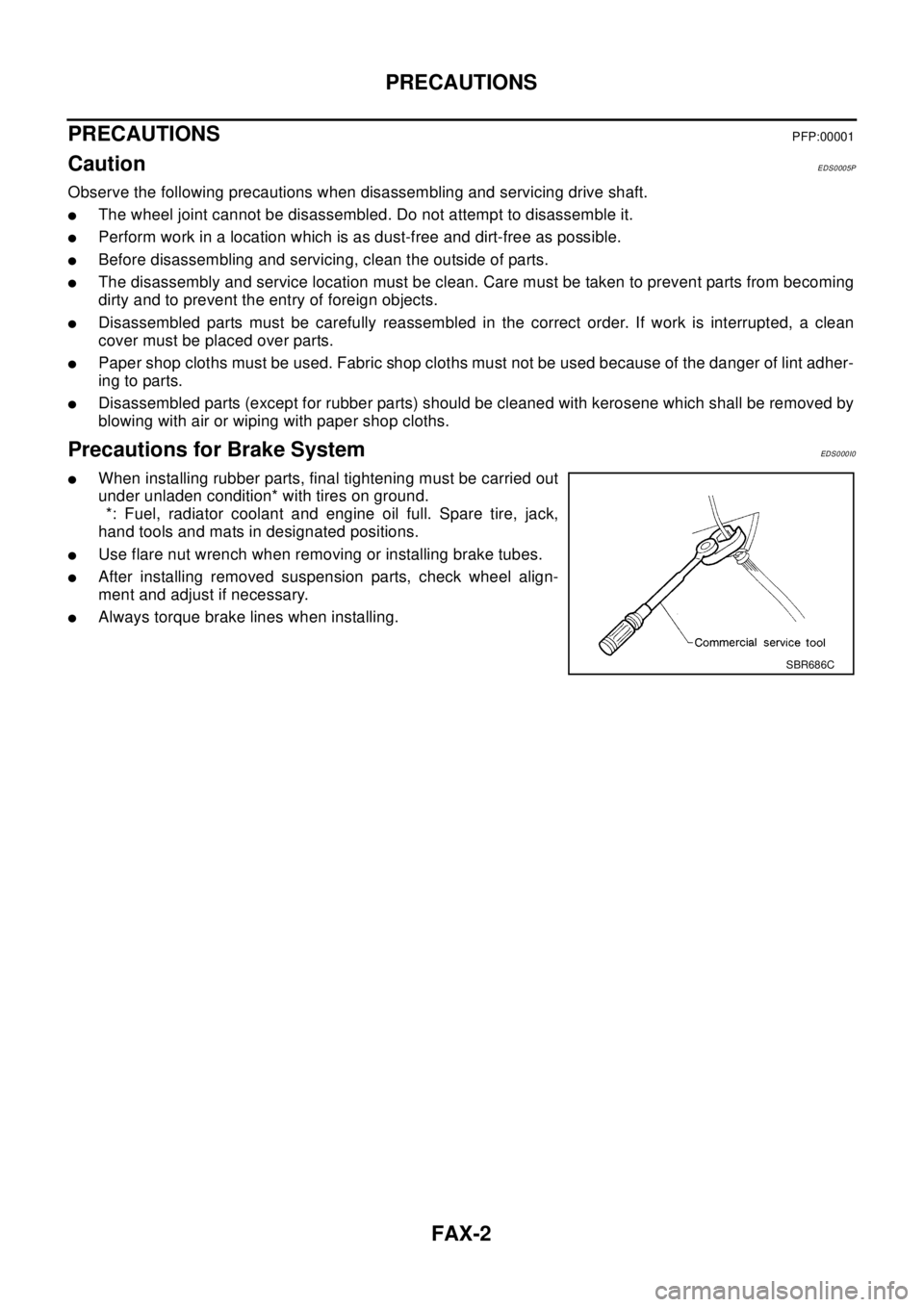
Precautions for Brake SystemEDS0 00 I0
lWhen installing rubber parts, final tightening must be carried out
under unladen condition* with tires on ground.
*: Fuel, radiator coolant and engine oil full. Spare tire, jack,
hand tools and mats in designated positions.
lUse flare nut wrench when removing or installing brake tubes.
lAfter installing removed suspension parts, check wheel align-
ment and adjust if necessary.
lAlways torque brake lines when installing.
SBR686C
Page 2241 of 3066

FSU-2
PRECAUTIONS
PRECAUTIONS
PFP:00001
CautionEES0006Z
lWhen installing rubber bushings, final tightening must be carried out under unladen conditions with tires
on flat, level ground. Oil will shorten the life of rubber bushings. Be sure to wipe off any spilled oil.
l“Unladen condition” means that fuel, coolant and lubricant are full and ready for drive. However, spare tire,
jack, and hand tools should be unloaded.
lAfter installing the removed suspension parts, always check wheel alignment and adjust if necessary.
lReplace the caulking nut with a new one. Install a new nut without wiping the oil off before tightening.
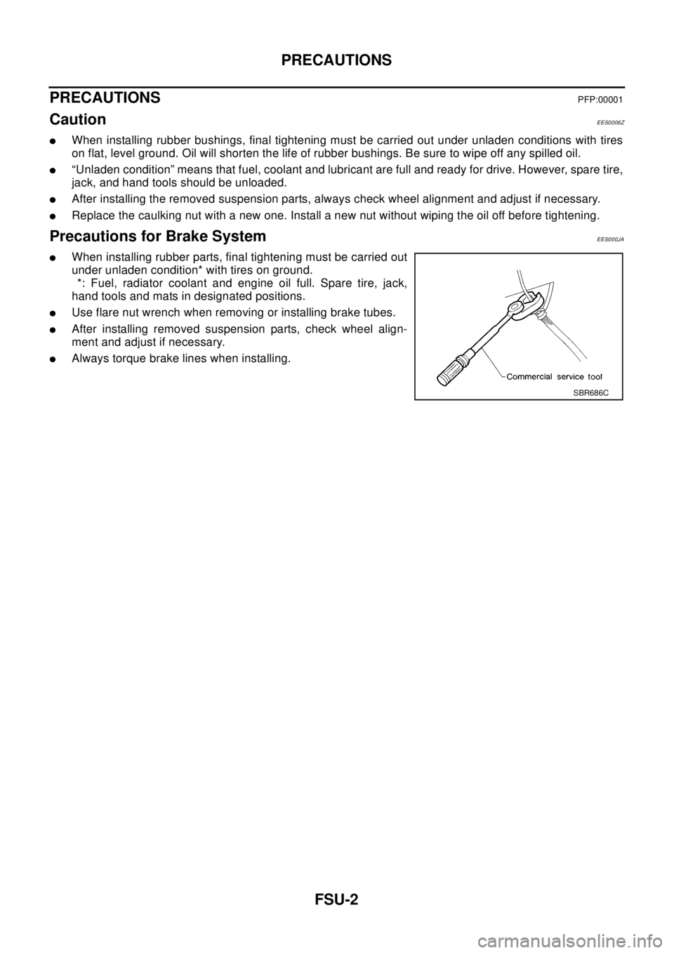
Precautions for Brake SystemEES000JA
lWhen installing rubber parts, final tightening must be carried out
under unladen condition* with tires on ground.
*: Fuel, radiator coolant and engine oil full. Spare tire, jack,
hand tools and mats in designated positions.
lUse flare nut wrench when removing or installing brake tubes.
lAfter installing removed suspension parts, check wheel align-
ment and adjust if necessary.
lAlways torque brake lines when installing.
SBR686C
Page 2252 of 3066

SERVICE DATA AND SPECIFICATIONS (SDS)
FSU-13
C
D
F
G
H
I
J
K
L
MA
B
FSU
SERVICE DATA AND SPECIFICATIONS (SDS)PFP:00030
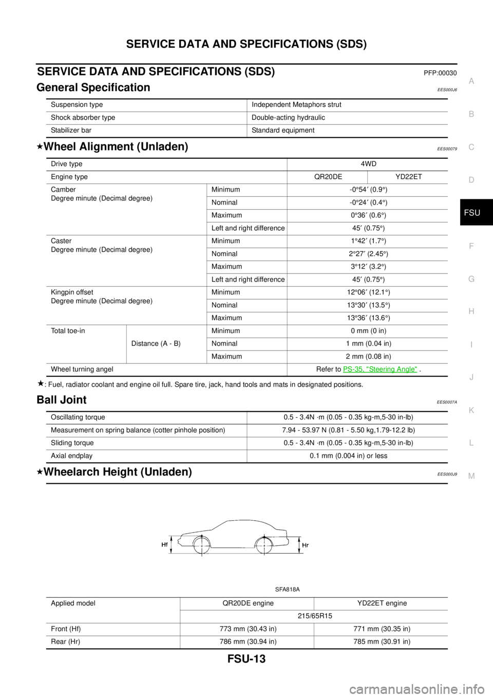
General SpecificationEES000J6
Wheel Alignment (Unladen)EES00079
: Fuel, radiator coolant and engine oil full. Spare tire, jack, hand tools and mats in designated positions.
Ball JointEES0007A
Wheelarch Height (Unladen)EES000J9
Suspension type Independent Metaphors strut
Shock absorber type Double-acting hydraulic
Stabilizer bar Standard equipment
Drive type4WD
Engine typeQR20DE YD22ET
Camber
Degree minute (Decimal degree)Minimum -0°54¢(0.9°)
Nominal -0°24¢(0.4°)
Maximum 0°36¢(0.6°)
Left and right difference 45¢(0.75°)
Caster
Degree minute (Decimal degree)Minimum 1°42¢(1.7°)
Nominal 2°27¢(2.45°)
Maximum 3°12¢(3.2°)
Left and right difference 45¢(0.75°)
Kingpin offset
Degree minute (Decimal degree)Minimum 12°06¢(12.1°)
Nominal 13°30¢(13.5°)
Maximum 13°36¢(13.6°)
To t a l t o e - i n
Distance (A - B)Minimum 0 mm (0 in)
Nominal 1 mm (0.04 in)
Maximum 2 mm (0.08 in)
Wheel turning angel Refer toPS-35, "
Steering Angle".
Oscillating torque 0.5 - 3.4N ·m (0.05 - 0.35 kg-m,5-30 in-lb)
Measurement on spring balance (cotter pinhole position) 7.94 - 53.97 N (0.81 - 5.50 kg,1.79-12.2 lb)
Sliding torque 0.5 - 3.4N ·m (0.05 - 0.35 kg-m,5-30 in-lb)
Axial endplay 0.1 mm (0.004 in) or less
Applied model QR20DE engine YD22ET engine
215/65R15
Front (Hf) 773 mm (30.43 in) 771 mm (30.35 in)
Rear (Hr) 786 mm (30.94 in) 785 mm (30.91 in)
SFA818A
Page 2253 of 3066
FSU-14
SERVICE DATA AND SPECIFICATIONS (SDS)
: Fuel, radiator coolant and engine oil full. Spare tire, jack, hand tools and mats in designated positions.
Page 2257 of 3066

GI-4
PRECAUTIONS
General Precautions
EAS000FQ
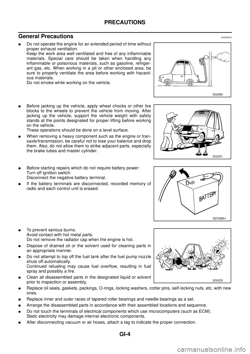
lDo not operate the engine for an extended period of time without
proper exhaust ventilation.
Keep the work area well ventilated and free of any inflammable
materials. Special care should be taken when handling any
inflammable or poisonous materials, such as gasoline, refriger-
ant gas, etc. When working in a pit or other enclosed area, be
sure to properly ventilate the area before working with hazard-
ous materials.
Do not smoke while working on the vehicle.
lBefore jacking up the vehicle, apply wheel chocks or other tire
blocks to the wheels to prevent the vehicle from moving. After
jacking up the vehicle, support the vehicle weight with safety
stands at the points designated for proper lifting before working
on the vehicle.
These operations should be done on a level surface.
lWhen removing a heavy component such as the engine or tran-
saxle/transmission, be careful not to lose your balance and drop
them. Also, do not allow them to strike adjacent parts, especially
the brake tubes and master cylinder.
lBefore starting repairs which do not require battery power:
Turn off ignition switch.
Disconnect the negative battery terminal.
lIf the battery terminals are disconnected, recorded memory of
radio and each control unit is erased.
lTo prevent serious burns:
Avoid contact with hot metal parts.
Do not remove the radiator cap when the engine is hot.
lDispose of drained oil or the solvent used for cleaning parts in
an appropriate manner.
lDo not attempt to top off the fuel tank after the fuel pump nozzle
shuts off automatically.
Continued refueling may cause fuel overflow, resulting in fuel
spray and possibly a fire.
lClean all disassembled parts in the designated liquid or solvent
prior to inspection or assembly.
lReplace oil seals, gaskets, packings, O-rings, locking washers, cotter pins, self-locking nuts, etc. with new
ones.
lReplace inner and outer races of tapered roller bearings and needle bearings as a set.
lArrange the disassembled parts in accordance with their assembled locations and sequence.
lDo not touch the terminals of electrical components which use microcomputers (such as ECM).
Static electricity may damage internal electronic components.
lAfter disconnecting vacuum or air hoses, attach a tag to indicate the proper connection.
SGI285
SGI231
SEF289H
SGI233