Page 74 of 3502
AT-66
TROUBLE DIAGNOSIS
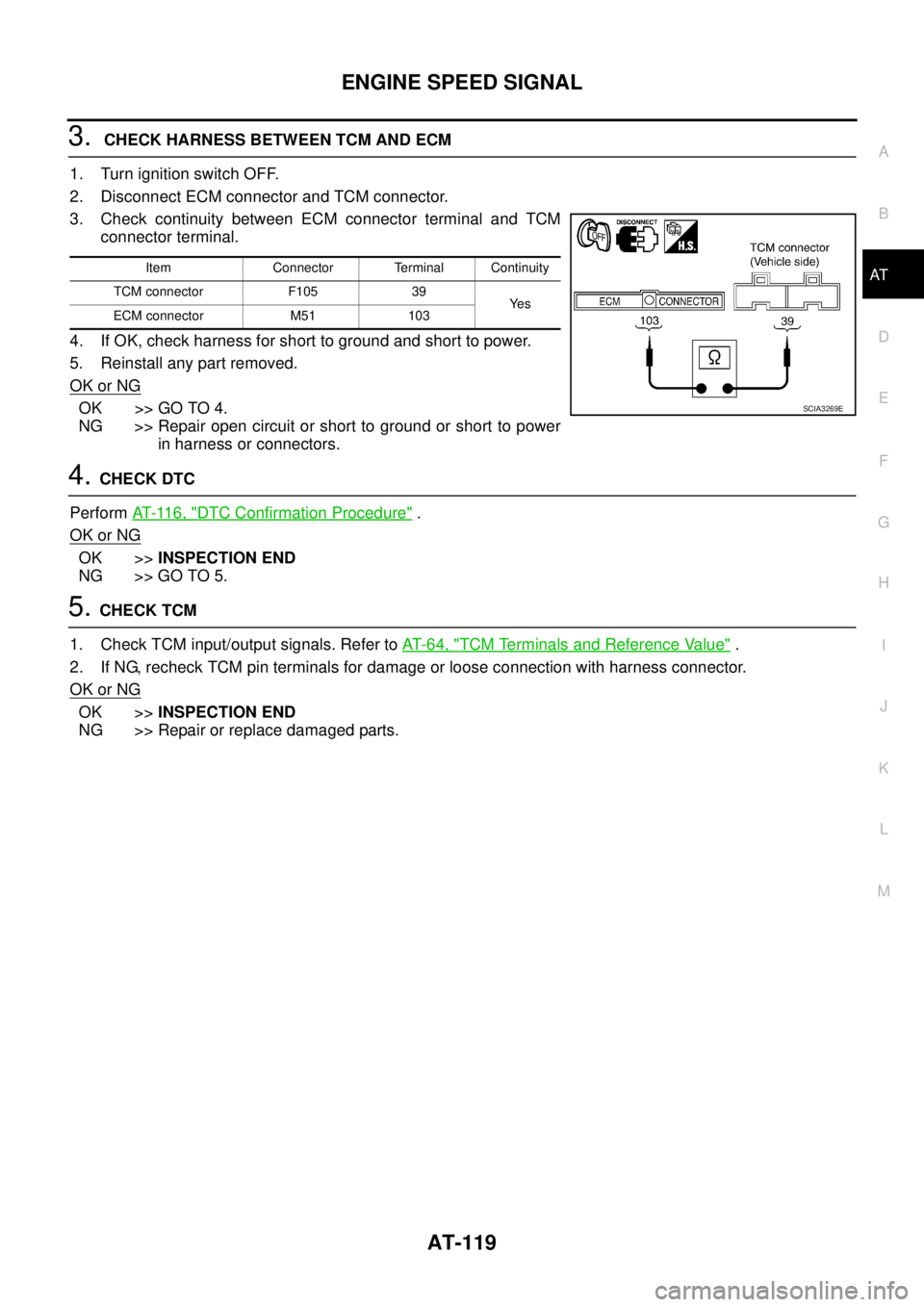
*: These terminals are connected to the ECM.
**: These terminals are connected to the data link connector.38 G/BTurbine revolution
sensor (power train
revolution sensor)When moving at 20 km/h (12 MPH) 240 Hz
39 * W/L Engine speed signal Refer to EC-72
(QR engine) or EC-415 (VQ engine)
40 L/B Vehicle speed sensorWhen moving vehicle at 2 to 3 km/h
(1 to 2 MPH) for 1 m (3 ft) or more.Voltage varies
between less
than 0 V and
more than 4.5 V
42 B Sensor ground Always 0 V
47 GA/T fluid temperature
sensor
and When ATF temperature is 20°C
(68°F).1.5 V
When ATF temperature is 80°C
(176°F).0.5 V
48 B Ground Always 0 V Terminal Wire color Item ConditionJudgement stan-
dard (Approx.)
Page 121 of 3502
BATT/FLUID TEMP SEN (A/T FLUID TEMP SENSOR CIRCUIT AND TCM POW-
ER SOURCE)
AT-113
D
E
F
G
H
I
J
K
L
MA
B
AT
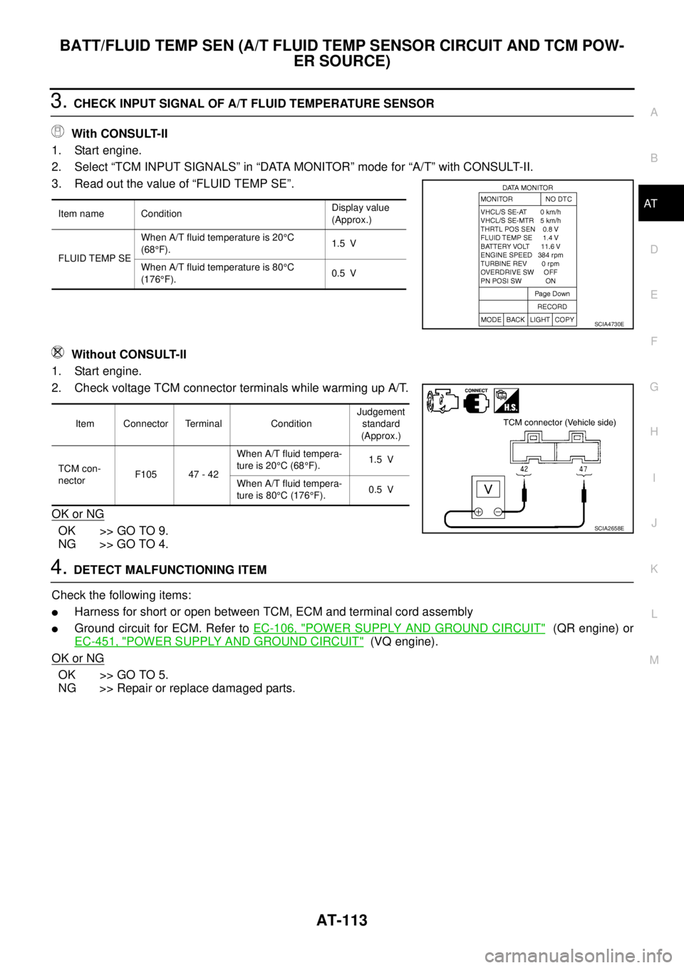
3. CHECK INPUT SIGNAL OF A/T FLUID TEMPERATURE SENSOR
With CONSULT-II
1. Start engine.
2. Select “TCM INPUT SIGNALS” in “DATA MONITOR” mode for “A/T” with CONSULT-II.
3. Read out the value of “FLUID TEMP SE”.
Without CONSULT-II
1. Start engine.
2. Check voltage TCM connector terminals while warming up A/T.
OK or NG
OK >> GO TO 9.
NG >> GO TO 4.
4. DETECT MALFUNCTIONING ITEM
Check the following items:
�Harness for short or open between TCM, ECM and terminal cord assembly
�Ground circuit for ECM. Refer to EC-106, "POWER SUPPLY AND GROUND CIRCUIT" (QR engine) or
EC-451, "
POWER SUPPLY AND GROUND CIRCUIT" (VQ engine).
OK or NG
OK >> GO TO 5.
NG >> Repair or replace damaged parts.
Item name ConditionDisplay value
(Approx.)
FLUID TEMP SEWhen A/T fluid temperature is 20°C
(68°F).1.5 V
When A/T fluid temperature is 80°C
(176°F).0.5 V
SCIA4730E
Item Connector Terminal ConditionJudgement
standard
(Approx.)
TCM con-
nectorF105 47 - 42When A/T fluid tempera-
ture is 20°C (68°F).1.5 V
When A/T fluid tempera-
ture is 80°C (176°F).0.5 V
SCIA2658E
Page 126 of 3502
AT-118
ENGINE SPEED SIGNAL
Data are reference value and are measured between each terminal and ground.
Diagnostic ProcedureBCS0012A
1. CHECK DTC WITH ECM
Check DTC with CONSULT-II “ENGINE”.
Turn ignition switch ON and select “SELF-DIAGNOSTIC RESULTS” mode for “ENGINE” with CONSULT-II.
Refer to EC-425, "
CONSULT-II Function (ENGINE)" .
OK or NG
OK >> GO TO 2.
NG >> Check ignition signal circuit for engine control. Refer to EC-735
.
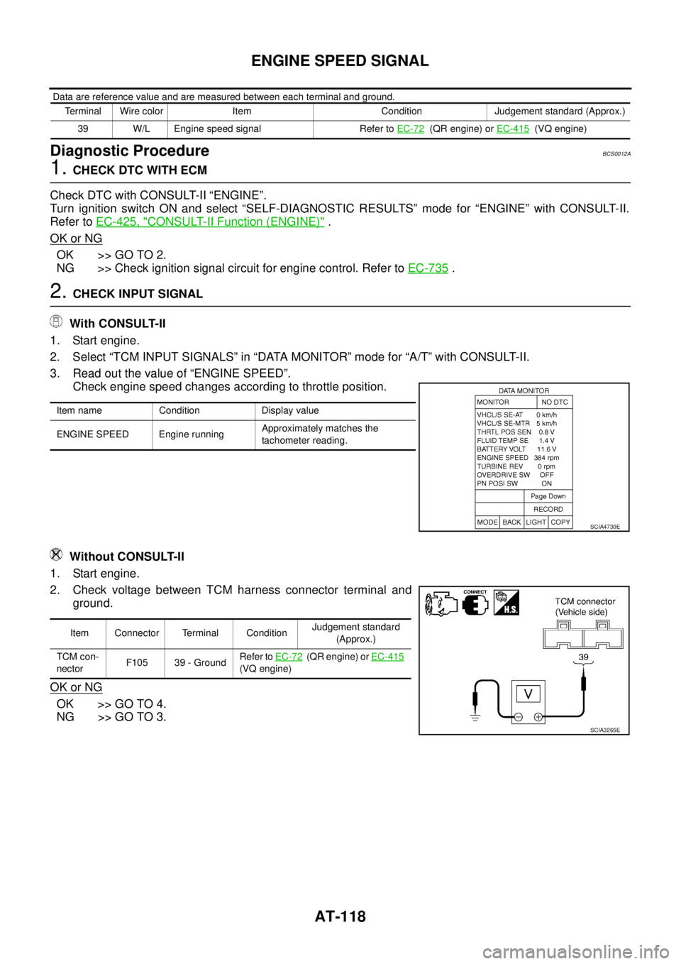
2. CHECK INPUT SIGNAL
With CONSULT-II
1. Start engine.
2. Select “TCM INPUT SIGNALS” in “DATA MONITOR” mode for “A/T” with CONSULT-II.
3. Read out the value of “ENGINE SPEED”.
Check engine speed changes according to throttle position.
Without CONSULT-II
1. Start engine.
2. Check voltage between TCM harness connector terminal and
ground.
OK or NG
OK >> GO TO 4.
NG >> GO TO 3.
Terminal Wire color Item Condition Judgement standard (Approx.)
39 W/L Engine speed signal Refer to EC-72
(QR engine) or EC-415 (VQ engine)
Item name Condition Display value
ENGINE SPEED Engine runningApproximately matches the
tachometer reading.
SCIA4730E
Item Connector Terminal ConditionJudgement standard
(Approx.)
TCM con-
nectorF105 39 - GroundRefer to EC-72
(QR engine) or EC-415
(VQ engine)
SCIA3265E
Page 127 of 3502
ENGINE SPEED SIGNAL
AT-119
D
E
F
G
H
I
J
K
L
MA
B
AT
3. CHECK HARNESS BETWEEN TCM AND ECM
1. Turn ignition switch OFF.
2. Disconnect ECM connector and TCM connector.
3. Check continuity between ECM connector terminal and TCM
connector terminal.
4. If OK, check harness for short to ground and short to power.
5. Reinstall any part removed.
OK or NG
OK >> GO TO 4.
NG >> Repair open circuit or short to ground or short to power
in harness or connectors.
4. CHECK DTC
Perform AT- 11 6 , "
DTC Confirmation Procedure" .
OK or NG
OK >>INSPECTION END
NG >> GO TO 5.
5. CHECK TCM
1. Check TCM input/output signals. Refer to AT- 6 4 , "
TCM Terminals and Reference Value" .
2. If NG, recheck TCM pin terminals for damage or loose connection with harness connector.
OK or NG
OK >>INSPECTION END
NG >> Repair or replace damaged parts.
Item Connector Terminal Continuity
TCM connector F105 39
Ye s
ECM connector M51 103
SCIA3269E
Page 185 of 3502
TROUBLE DIAGNOSIS FOR SYMPTOMS
AT-177
D
E
F
G
H
I
J
K
L
MA
B
AT
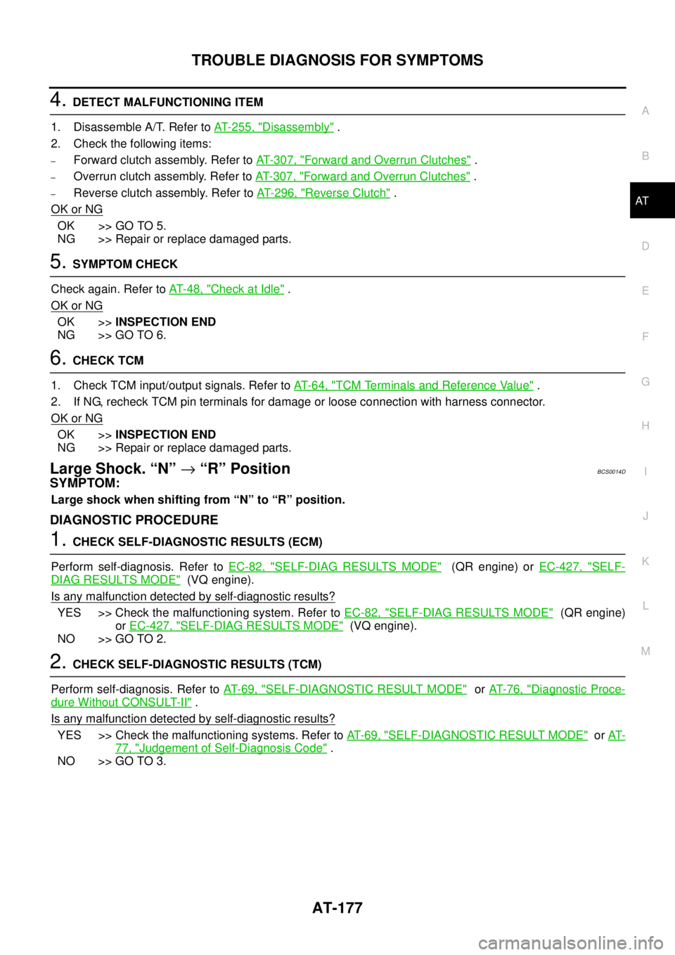
4. DETECT MALFUNCTIONING ITEM
1. Disassemble A/T. Refer to AT- 2 5 5 , "
Disassembly" .
2. Check the following items:
–Forward clutch assembly. Refer to AT- 3 0 7 , "Forward and Overrun Clutches" .
–Overrun clutch assembly. Refer to AT- 3 0 7 , "Forward and Overrun Clutches" .
–Reverse clutch assembly. Refer to AT- 2 9 6 , "Reverse Clutch" .
OK or NG
OK >> GO TO 5.
NG >> Repair or replace damaged parts.
5. SYMPTOM CHECK
Check again. Refer to AT- 4 8 , "
Check at Idle" .
OK or NG
OK >>INSPECTION END
NG >> GO TO 6.
6. CHECK TCM
1. Check TCM input/output signals. Refer to AT- 6 4 , "
TCM Terminals and Reference Value" .
2. If NG, recheck TCM pin terminals for damage or loose connection with harness connector.
OK or NG
OK >>INSPECTION END
NG >> Repair or replace damaged parts.
Large Shock. “N” → “R” PositionBCS0014D
SYMPTOM:
Large shock when shifting from “N” to “R” position.
DIAGNOSTIC PROCEDURE
1. CHECK SELF-DIAGNOSTIC RESULTS (ECM)
Perform self-diagnosis. Refer to EC-82, "
SELF-DIAG RESULTS MODE" (QR engine) or EC-427, "SELF-
DIAG RESULTS MODE" (VQ engine).
Is any malfunction detected by self-diagnostic results?
YES >> Check the malfunctioning system. Refer to EC-82, "SELF-DIAG RESULTS MODE" (QR engine)
or EC-427, "
SELF-DIAG RESULTS MODE" (VQ engine).
NO >> GO TO 2.
2. CHECK SELF-DIAGNOSTIC RESULTS (TCM)
Perform self-diagnosis. Refer to AT- 6 9 , "
SELF-DIAGNOSTIC RESULT MODE" or AT- 7 6 , "Diagnostic Proce-
dure Without CONSULT-II" .
Is any malfunction detected by self-diagnostic results?
YES >> Check the malfunctioning systems. Refer to AT- 6 9 , "SELF-DIAGNOSTIC RESULT MODE" or AT-
77, "Judgement of Self-Diagnosis Code" .
NO >> GO TO 3.
Page 218 of 3502

AT-210
TROUBLE DIAGNOSIS FOR SYMPTOMS
6. DETECT MALFUNCTIONING ITEM
1. Remove control valve assembly. Refer to AT- 2 2 5 , "
Control Valve Assembly and Accumulators" .
2. Check the following items:
–Shift valve A
–Overrun clutch solenoid valve
3. Disassemble A/T. Refer to AT- 2 5 5 , "
Disassembly" .
4. Check the following items:
–Overrun clutch assembly. Refer to AT- 3 0 7 , "Forward and Overrun Clutches" .
–Low & reverse brake assembly. Refer to AT- 3 1 5 , "Low & Reverse Brake" .
OK or NG
OK >> GO TO 7.
NG >> Repair or replace damaged parts.
7. SYMPTOM CHECK
Check again. Refer to AT- 5 2 , "
Cruise Test — Part 3" .
OK or NG
OK >>INSPECTION END
NG >> GO TO 8.
8. CHECK TCM
1. Check TCM input/output signals. Refer to AT- 6 4 , "
TCM Terminals and Reference Value" .
2. If NG, recheck TCM pin terminals for damage or loose connection with harness connector.
OK or NG
OK >> INSPECTION END
NG >> Repair or replace damaged parts.
TCM Self-diagnosis Does Not ActivateBCS0014V
SYMPTOM:
A/T CHECK indicator lamp does not come on in TCM self-diagnostic procedure even if the lamp circuit
is good.
DESCRIPTION
�PNP switch
PNP switch includes a transmission range switch. The transmission range switch detects the selector
lever position and sends a signal to the TCM.
�3rd position switch
3rd position switch detects the 3rd position and sends a signal via CAN communication to the TCM.
�Closed throttle position signal and wide-open throttle position signal.
ECM judges throttle opening based on a signal from accelerator pedal position (APP) sensor, and sends
the signal via CAN communication to TCM.
�Stop lamp switch
Stop lamp switch detects the switch position (ON or OFF) and sends a signal via CAN communication to
the TCM.
DIAGNOSTIC PROCEDURE
NOTE:
The diagnostic procedure includes inspection for the park/neutral position (PNP) stitch, 3rd position switch,
stop lamp switch, closed throttle position signal and wide open throttle position signal circuit. Refer to AT- 1 6 1 ,
"PNP, 3RD POSITION SWITCH AND CLOSED THROTTLE, WIDE OPEN THROTTLE POSITION SIGNAL"
and AT- 1 6 7 , "BRAKE SIGNAL CIRCUIT" .
Page 219 of 3502
TRANSMISSION CONTROL MODULE
AT-211
D
E
F
G
H
I
J
K
L
MA
B
AT
TRANSMISSION CONTROL MODULEPFP:31036
Removal and InstallationBCS001PR
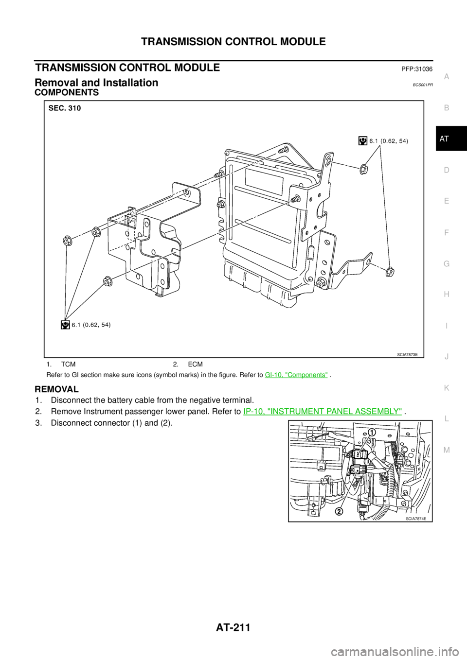
COMPONENTS
REMOVAL
1. Disconnect the battery cable from the negative terminal.
2. Remove Instrument passenger lower panel. Refer to IP-10, "
INSTRUMENT PANEL ASSEMBLY" .
3. Disconnect connector (1) and (2).
1. TCM 2. ECM
Refer to GI section make sure icons (symbol marks) in the figure. Refer to GI-10, "
Components" .
SCIA7873E
SCIA7874E
Page 457 of 3502

TROUBLE DIAGNOSIS
ATC-79
C
D
E
F
G
H
I
K
L
MA
B
AT C
SYSTEM DESCRIPTION
Unified meter and A/C amp. controls compressor operation by intake air temperature and signal from ECM.
Low Temperature Protection Control
Unified meter and A/C amp. will turn the compressor ON or OFF as determined by a signal detected by intake
sensor.
When intake air temperature is higher than 4°C (39°F), the compres-
sor turns ON. The compressor turns OFF when intake air tempera-
ture is lower than 2.5°C (37°F).
DIAGNOSIS PROCEDURE FOR MAGNET CLUTCH
SYMPTOM: Magnet clutch does not engage when A/C switch is ON.
1. CHECK INTAKE SENSOR CIRCUIT
Check intake sensor. Refer to AT C - 4 7 , "
FUNCTION CONFIRMATION PROCEDURE" , see No. 11.
OK or NG
OK >> GO TO 2.
NG >> Malfunctioning intake sensor: Refer to ATC-105, "
Intake Sensor Circuit" .
2. PERFORM AUTO ACTIVE TEST
Refer to PG-21, "
Auto Active Test" .
Does the magnet clutch operate?
YES >>�WITH CONSULT-II: GO TO 5.
�WITHOUT CONSULT-II: GO TO 6.
NO >> Check 10 A fuse (No. 79, located in IPDM E/R). Refer to PG-25, "
IPDM E/R Terminal Arrange-
ment" , and GO TO 3.
RHA094GD
PJIA0011E