Page 2393 of 3502
BDS0007N
COMPONENT
REMOVAL
1. Remove tires from vehicle.
2. Remove wheel sensor from steering knuckle. Refer to BRC-")
FRONT DRIVE SHAFT
FAX-11
C
E
F
G
H
I
J
K
L
MA
B
FA X
Removal and Installation (LH)BDS0007N
COMPONENT
REMOVAL
1. Remove tires from vehicle.
2. Remove wheel sensor from steering knuckle. Refer to BRC-33, "
WHEEL SENSORS" .
CAUTION:
Do not pull on wheel sensor harness.
3. Remove torque member fixing bolts. Hang torque member in a place where it will not interfere with work.
Refer to BR-26, "
FRONT DISC BRAKE" .
NOTE:
Do not depress brake pedal while brake caliper is removed.
4. Remove disc rotor. Refer to FAX-5, "
Removal and Installation" .
5. Remove cotter pin, then loosen hub lock nut.
6. Separate wheel hub and bearing assembly from drive shaft by
lightly tapping the end with hammer (suitable tool) and a wood
block, and then remove lock nut.
CAUTION:
�Do not place drive shaft joint at an extreme angle. Also be
careful not to overextend slide joint.
�Do not allow drive shaft to hang down without support for
housing (or joint sub-assembly), shaft and the other
parts.
NOTE:
Use a puller (suitable tool) if wheel hub and bearing assembly
and drive shaft cannot be separated even after performing the
above procedure.
7. Remove fixing nuts and bolts, and then remove steering knuckle
from strut assembly. Refer to FSU-7, "
Components" .
8. Remove drive shaft from wheel hub and bearing assembly.
1. Drive shaft 2. Cotter pin
SDIA1761E
SDIA1821E
SEIA0411J
Page 2395 of 3502
BDS0007O
COMPONENT
REMOVAL
1. Remove tires from vehicle.
2. Remove wheel sensor from steering knuckle. Refer to BRC-")
FRONT DRIVE SHAFT
FAX-13
C
E
F
G
H
I
J
K
L
MA
B
FA X
Removal and Installation (RH)BDS0007O
COMPONENT
REMOVAL
1. Remove tires from vehicle.
2. Remove wheel sensor from steering knuckle. Refer to BRC-33, "
WHEEL SENSORS" .
CAUTION:
Do not pull on wheel sensor harness.
3. Remove torque member fixing bolts. Hang torque member in a place where it will not interfere with work.
Refer to BR-26, "
FRONT DISC BRAKE" .
NOTE:
Do not depress brake pedal while brake caliper is removed.
4. Remove disc rotor. Refer to FAX-5, "
Removal and Installation" .
5. Remove cotter pin, then loosen hub lock nut.
6. Separate wheel hub and bearing assembly from drive shaft by
lightly tapping the end with hummer (suitable tool) and a wood
block, and then remove hub lock nut.
CAUTION:
�Do not place drive shaft joint at an extreme angle. Also be
careful not to overextend slide joint.
�Do not allow drive shaft to hang down without support for
housing (or joint sub-assembly), shaft and the other
parts.
NOTE:
Use a puller (suitable tool) if wheel hub and bearing assembly
and drive shaft cannot be separated even after performing the
above procedure.
7. Remove fixing nuts and bolts, and then remove steering knuckle
from strut assembly. Refer to FSU-7, "
Components" .
8. Remove drive shaft from wheel hub and bearing assembly.
1. Cotter pin 2. Drive shaft 3. Support bearing bracket
4. Dynamic damper (Except for
VQ35DE models)
SDIA2597E
SDIA1821E
SEIA0411J
Page 2417 of 3502

FL-1
FUEL SYSTEM
B ENGINE
CONTENTS
C
D
E
F
G
H
I
J
K
L
M
SECTION FL
A
FL
FUEL SYSTEM
PREPARATION ........................................................... 2
Commercial Service Tools ........................................ 2
FUEL SYSTEM ........................................................... 3
Checking Fuel Lines ................................................. 3
General Precautions ................................................ 3
FUEL LEVEL SENSOR UNIT, FUEL FILTER AND
FUEL PUMP ASSEMBLY ........................................... 4
Removal and Installation .......................................... 4
REMOVAL ............................................................. 4
INSTALLATION ..................................................... 7
INSPECTION AFTER INSTALLATION ................. 7FUEL TANK ................................................................ 8
Removal and Installation .......................................... 8
REMOVAL ............................................................. 8
INSTALLATION ..................................................... 9
INSPECTION AFTER INSTALLATION .................. 9
SERVICE DATA AND SPECIFICATIONS (SDS) ...... 11
Standard and Limit .................................................. 11
Page 2420 of 3502

FL-4
FUEL LEVEL SENSOR UNIT, FUEL FILTER AND FUEL PUMP ASSEMBLY
FUEL LEVEL SENSOR UNIT, FUEL FILTER AND FUEL PUMP ASSEMBLYPFP:17042
Removal and InstallationBBS005AG
REMOVAL
WARNING:
Be sure to read “General Precautions” before working on the fuel system. Refer to FL-3, "
General Pre-
cautions" .
1. Check fuel level on fuel gauge. If fuel gauge indicates more than
the level as shown in the figure (full or almost full), drain fuel
from fuel tank until fuel gauge indicates level as shown in the fig-
ure or below.
NOTE:
Because fuel will be spilled when removing fuel level sensor unit
for the top of fuel is above the fuel level sensor unit installation
surface.
�As a guide, fuel level becomes the position as shown in the
figure or below when approximately 10 (2-1/4 Imp gal) of
fuel are drained from fuel tank.
�In a case that fuel pump does not operate, perform the follow-
ing procedure.
a. Insert hose of less than 25 mm (0.98 in) in diameter into fuel filler tube through fuel filler opening to draw
fuel from fuel filler tube.
b. Disconnect fuel filler hose from fuel filler tube. Refer to FL-8, "
FUEL TANK" .
c. Insert hose into fuel tank through fuel filler hose to draw fuel from fuel tank.
2. Release the fuel pressure from the fuel lines. Refer to EC-49, "
FUEL PRESSURE RELEASE" (QR20DE
), or EC-392, "
FUEL PRESSURE RELEASE" (VQ23DE and VQ35DE).
3. Open fuel filler lid.
4. Open fuel filler cap and release the pressure inside fuel tank.
5. Remove rear seat cushion. Refer to SE-112, "
REAR SEAT" .
1. Lock ring 2.Fuel level sensor unit, fuel filter and
fuel pump assembly3. Seal packing
PBIC2519E
KBIA1942J
Page 2421 of 3502
FUEL LEVEL SENSOR UNIT, FUEL FILTER AND FUEL PUMP ASSEMBLY
FL-5
C
D
E
F
G
H
I
J
K
L
MA
FL
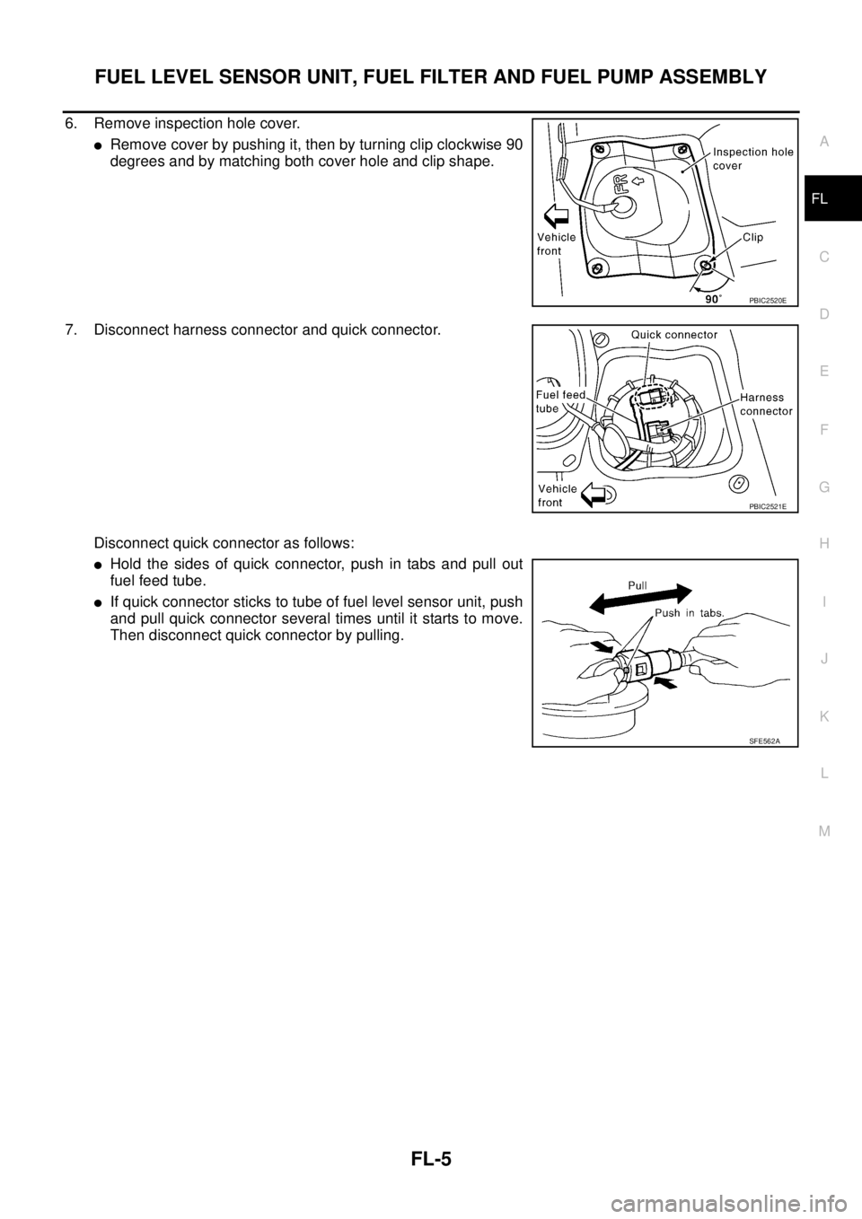
6. Remove inspection hole cover.
�Remove cover by pushing it, then by turning clip clockwise 90
degrees and by matching both cover hole and clip shape.
7. Disconnect harness connector and quick connector.
Disconnect quick connector as follows:
�Hold the sides of quick connector, push in tabs and pull out
fuel feed tube.
�If quick connector sticks to tube of fuel level sensor unit, push
and pull quick connector several times until it starts to move.
Then disconnect quick connector by pulling.
PBIC2520E
PBIC2521E
SFE562A
Page 2422 of 3502

FL-6
FUEL LEVEL SENSOR UNIT, FUEL FILTER AND FUEL PUMP ASSEMBLY
CAUTION:
�Quick connector can be disconnected when the tabs
are completely depressed. Do not twist it more than
necessary.
�Do not use any tools to disconnected quick connector.
�Keep resin tube away from heat. Be especially careful
when welding near the resin tube.
�Prevent acid liquid such as battery electrolyte, etc.
from getting on resin tube.
�Do not bend or twist resin tube during installation and
disconnection.
�Do not remove the remaining retainer on hard tube (or
the equivalent) except when resin tube or retainer is
replaced.
�When resin tube or hard tube (or the equivalent) is
replaced, also replace retainer with new one.
�Replace same color retainer as before replacing.
�To keep the connecting portion clean and to avoid
damage and foreign materials, cover them completely
with plastic bags or something similar.
8. Using fuel tank lock ring wrench (commercial service tool),
remove lock ring.
9. Remove fuel level sensor unit, fuel filter and fuel pump assem-
bly.
CAUTION:
�Do not bend float arm during removal.
�Avoid polluting the inside by residue fuel. Draw out with
avoiding inclination by supporting with a cloth.
�Avoid impacts such as falling when handling compo-
nents.Retainer color: White
SBIA0504E
PBIC0163E
PBIC0240E
PBIC2522E
Page 2423 of 3502

FUEL LEVEL SENSOR UNIT, FUEL FILTER AND FUEL PUMP ASSEMBLY
FL-7
C
D
E
F
G
H
I
J
K
L
MA
FL
INSTALLATION
Note the following, and install in the reverse order of removal.
Fuel Level Sensor Unit, Fuel Filter and Fuel Pump Assembly
1. Install seal packing to fuel tank without any twist.
2. Align “B” with “A” as shown in the figure. Install fuel level sensor
unit, fuel filter and fuel pump assembly to fuel tank.
CAUTION:
Do not bend float arm during installing.
3. Tighten lock ring with lock ring wrench (commercial service tool).
CAUTION:
Install lock ring horizontally.
Quick Connector
Connect quick connector of fuel feed hose as follows:
1. Check the connection for damage or any foreign materials.
2. Align the connector with the tube, then insert the connector straight into the tube until a click sound is
heard.
3. After connecting, make sure that the connection is secure by following method.
�Visually confirm that the two tabs are connected to the connector.
�Pull the tube and the connector to make sure they are
securely connected.
Inspection Hole Cover
1. Install inspection hole cover with front mark (arrow) facing front of vehicle.
2. Lock clips by turning counter-clockwise.
INSPECTION AFTER INSTALLATION
Use the following procedure to check for fuel leaks.
1. Turn ignition switch “ON” (with engine stopped), then check connections for leaks by applying fuel pres-
sure to fuel piping.
2. Start engine and rev it up and make sure there are no fuel leaks at the fuel system connections.
A : Arrow mark (Fuel tank side)
B : Positioning mark
C : Fuel tank
: Vehicle front
PBIC4584J
PBIC1653E
Page 2424 of 3502

FL-8
FUEL TANK
FUEL TANKPFP:17202
Removal and InstallationBBS005AI
REMOVAL
WARNING:
Be sure to read “General Precautions” before working on the fuel system. Refer to FL-3, "
General Pre-
cautions" .
�Drain fuel from fuel tank if necessary. Refer to FL-4, "REMOVAL" .
CAUTION:
For the safety work and to maintain fuel tank gravity at center, drain fuel to the level where fuel
tank weight at left and right becomes equal.
�Perform work on level place.
1. Perform steps 2 to 7 of “REMOVAL” in “FUEL LEVEL SENSOR UNIT, FUEL FILTER AND FUEL PUMP
ASSEMBLY”. Refer to FL-4, "
REMOVAL" .
2. Remove center muffler. Refer to EX-2, "
EXHAUST SYSTEM" .
3. Remove center muffler mounting rubber. Refer to EX-2, "
EXHAUST SYSTEM" .
4. Move parking brake rear right and left cables from the lower part of fuel tank. Refer to PB-3, "
PA R K I N G
BRAKE CONTROL" .
5. Support bottom of rear suspension member with transmission jack, and descend rear suspension assem-
bly. Refer to RSU-5, "
REAR SUSPENSION ASSEMBLY" .
6. Remove fuel tank protector.
1. Fuel filler tube 2. Vent hose 3. Fuel tank
4. Fuel tank mounting band 5. Clip 6. Fuel tank protector
7. Fuel tank mounting band 8. Fuel filler hose 9. Grommet
10. Fuel filler cap 11. EVAP hose
PBIC2527E