Page 2283 of 3502
![NISSAN TEANA 2003 Service Manual TIMING CHAIN
EM-175
[VQ]
C
D
E
F
G
H
I
J
K
L
MA
EM
12. Obtain No. 1 cylinder at TDC of its compression stroke as follows:
a. Rotate crankshaft pulley clockwise to align timing mark (grooved
line wit](/manual-img/5/57392/w960_57392-2282.png "NISSAN TEANA 2003 Service Manual TIMING CHAIN
EM-175
[VQ]
C
D
E
F
G
H
I
J
K
L
MA
EM
12. Obtain No. 1 cylinder at TDC of its compression stroke as follows:
a. Rotate crankshaft pulley clockwise to align timing mark (grooved
line wit")
TIMING CHAIN
EM-175
[VQ]
C
D
E
F
G
H
I
J
K
L
MA
EM
12. Obtain No. 1 cylinder at TDC of its compression stroke as follows:
a. Rotate crankshaft pulley clockwise to align timing mark (grooved
line without color) with timing indicator.
b. Make sure that intake and exhaust cam noses on No. 1 cylinder
(engine front side of right bank) are located as shown in the fig-
ure.
�If not, turn crankshaft one revolution (360 degrees) and align
as shown in the figure.
13. Remove crankshaft pulley as follows:
a. Fix crankshaft with pulley holder (SST).
b. Loosen crankshaft pulley bolt and locate bolt seating surface at
10 mm (0.39 in) from its original position.
CAUTION:
Do not remove crankshaft pulley bolt as it will be used as a
supporting point for suitable puller.
c. Place suitable puller tab on holes of crankshaft pulley, and pull
crankshaft pulley through.
CAUTION:
Do not put suitable puller tab on crankshaft pulley periph-
ery, as this will damage internal damper.
14. Remove front timing chain case as follows:
SEM918G
SEM418G
PBIC2475E
SEM915E
Page 2287 of 3502
TIMING CHAIN
EM-179
[VQ]
C
D
E
F
G
H
I
J
K
L
MA
EM
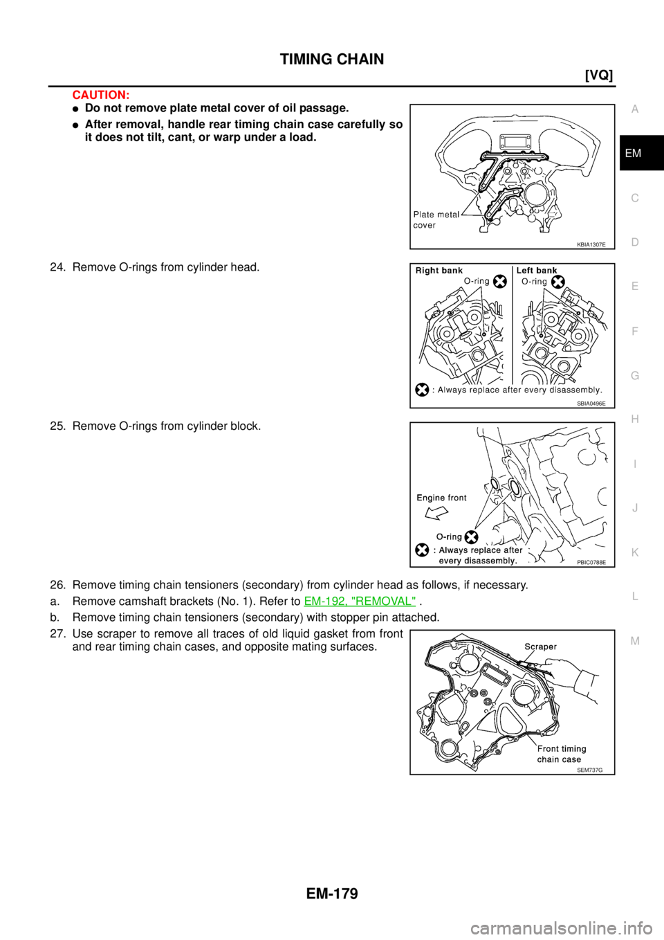
CAUTION:
�Do not remove plate metal cover of oil passage.
�After removal, handle rear timing chain case carefully so
it does not tilt, cant, or warp under a load.
24. Remove O-rings from cylinder head.
25. Remove O-rings from cylinder block.
26. Remove timing chain tensioners (secondary) from cylinder head as follows, if necessary.
a. Remove camshaft brackets (No. 1). Refer to EM-192, "
REMOVAL" .
b. Remove timing chain tensioners (secondary) with stopper pin attached.
27. Use scraper to remove all traces of old liquid gasket from front
and rear timing chain cases, and opposite mating surfaces.
KBIA1307E
SBIA0496E
PBIC0788E
SEM737G
Page 2289 of 3502
TIMING CHAIN
EM-181
[VQ]
C
D
E
F
G
H
I
J
K
L
MA
EM
INSTALLATION
NOTE:
The below figure shows the relationship between the mating mark on each timing chain and that on the corre-
sponding sprocket, with the components installed.
1. Install timing chain tensioners (secondary) to cylinder head as follows if removed. Refer to EM-197,
"INSTALLATION" .
a. Install timing chain tensioners (secondary) with stopper pin attached and new O-ring.
b. Install camshaft brackets (No. 1). Refer to EM-197, "
INSTALLATION" .
2. Install rear timing chain case as follows:
a. Install new O-rings onto cylinder block.
PBIC3590E
PBIC0788E
Page 2290 of 3502
EM-182
[VQ]
TIMING CHAIN
b. Install new O-rings to cylinder head.
c. Apply liquid gasket with tube presser [SST: WS39930000] to rear timing chain case back side as shown in
the figure.
Use Genuine Liquid Gasket or equivalent.
CAUTION:
�For “A” in the figure, completely wipe out liquid gasket extended on a portion touching at
engine coolant.
�Apply liquid gasket on installation position of water pump and cylinder head very completely.
d. Align rear timing chain case and water pump assembly with dowel pins (right and left) on cylinder block
and install rear timing chain case.
�Make sure O-rings stay in place during installation to cylinder block and cylinder head.
SBIA0496E
PBIC2616E
Page 2291 of 3502
![NISSAN TEANA 2003 Service Manual TIMING CHAIN
EM-183
[VQ]
C
D
E
F
G
H
I
J
K
L
MA
EM
e. Tighten mounting bolts in numerical order as shown in the fig-
ure.
�There are two types of mounting bolt. Refer to the following
for locating b](/manual-img/5/57392/w960_57392-2290.png "NISSAN TEANA 2003 Service Manual TIMING CHAIN
EM-183
[VQ]
C
D
E
F
G
H
I
J
K
L
MA
EM
e. Tighten mounting bolts in numerical order as shown in the fig-
ure.
�There are two types of mounting bolt. Refer to the following
for locating b")
TIMING CHAIN
EM-183
[VQ]
C
D
E
F
G
H
I
J
K
L
MA
EM
e. Tighten mounting bolts in numerical order as shown in the fig-
ure.
�There are two types of mounting bolt. Refer to the following
for locating bolts.
f. After all bolts tightening, retighten them to the specified in
numerical order as shown in the figure.
�If liquid gasket protrudes, wipe it off immediately.
g. After installing rear timing chain case, check surface height dif-
ference between the following parts on the oil pan (upper)
mounting surface.
�If not within standard, repeat the installation procedure.
3. Install water pump with new O-rings. Refer to CO-46, "
WATER PUMP" .
4. Make sure that dowel pin hole, dowel pin and crankshaft key are
located as shown in the figure. (No. 1 cylinder at compression
TDC)
NOTE:
Though camshaft does not stop at the position as shown in the
figure, for the placement of cam nose, it is generally accepted
camshaft is placed for the same direction of the figure.
CAUTION:
Hole on small dia. side must be used for intake side dowel pin hole. Do not misidentify (ignore big
dia. side).
5. Install timing chain (secondary) and camshaft sprockets (INT and EXH) as follows:
CAUTION:
Mating marks between timing chain and sprockets slip easily. Confirm all mating mark positions
repeatedly during the installation process.Bolt length: Bolt position
20 mm (0.79 in) : 1, 2, 3, 6, 7, 8, 9, 10
16 mm (0.63 in) : Except the above
: 12.7 N·m (1.3 kg-m, 9 ft-lb)
SEM735G
Standard
Rear timing chain case to cylinder block:
−0.24 to 0.14 mm (−0.009 to 0.006 in)
SEM943G
Camshaft dowel pin hole (intake side)
: At cylinder head upper face side in each bank
Camshaft dowel pin (exhaust side)
: At cylinder head upper face side in each bank
Crankshaft key
: At cylinder head side of right bank
KBIA1073E
Page 2299 of 3502
![NISSAN TEANA 2003 Service Manual TIMING CHAIN
EM-191
[VQ]
C
D
E
F
G
H
I
J
K
L
MA
EM
e. Rotate crankshaft pulley in normal direction (clockwise when viewed from engine front) to confirm it turns
smoothly.
17. For the following opera](/manual-img/5/57392/w960_57392-2298.png "NISSAN TEANA 2003 Service Manual TIMING CHAIN
EM-191
[VQ]
C
D
E
F
G
H
I
J
K
L
MA
EM
e. Rotate crankshaft pulley in normal direction (clockwise when viewed from engine front) to confirm it turns
smoothly.
17. For the following opera")
TIMING CHAIN
EM-191
[VQ]
C
D
E
F
G
H
I
J
K
L
MA
EM
e. Rotate crankshaft pulley in normal direction (clockwise when viewed from engine front) to confirm it turns
smoothly.
17. For the following operations, perform steps in the reverse order of removal.
INSPECTION AFTER INSTALLATION
Inspection for Leaks
The following are procedures for checking fluids leak, lubricates leak and exhaust gases leak.
�Before starting engine, check oil/fluid levels including engine coolant and engine oil. If less than required
quantity, fill to the specified level. Refer to MA-14, "
RECOMMENDED FLUIDS AND LUBRICANTS" .
�Use procedure below to check for fuel leakage.
–Turn ignition switch “ON” (with engine stopped). With fuel pressure applied to fuel piping, check for fuel
leakage at connection points.
–Start engine. With engine speed increased, check again for fuel leakage at connection points.
�Run engine to check for unusual noise and vibration.
NOTE:
If hydraulic pressure inside timing chain tensioner drops after removal/installation, slack in the guide may
generate a pounding noise during and just after engine start. However, this is normal. Noise will stop after
hydraulic pressure rises.
�Warm up engine thoroughly to make sure there is no leakage of fuel, exhaust gases, or any oil/fluids
including engine oil and engine coolant.
�Bleed air from lines and hoses of applicable lines, such as in cooling system.
�After cooling down engine, again check oil/fluid levels including engine oil and engine coolant. Refill to the
specified level, if necessary.
Summary of the inspection items:
* Transmission/transaxle/CVT fluid. power steering fluid, brake fluid, etc.Item Before starting engine Engine running After engine stopped
Engine coolant Level Leakage Level
Engine oil Level Leakage Level
Other oils and fluid* Level Leakage Level
Fuel Leakage Leakage Leakage
Exhaust gases — Leakage —
Page 2301 of 3502
![NISSAN TEANA 2003 Service Manual CAMSHAFT
EM-193
[VQ]
C
D
E
F
G
H
I
J
K
L
MA
EM
2. Install engine sub-attachment with engine stand shaft [SST: KV10117001 and KV10106500] to right side
of cylinder block, then lift engine, and mount](/manual-img/5/57392/w960_57392-2300.png "NISSAN TEANA 2003 Service Manual CAMSHAFT
EM-193
[VQ]
C
D
E
F
G
H
I
J
K
L
MA
EM
2. Install engine sub-attachment with engine stand shaft [SST: KV10117001 and KV10106500] to right side
of cylinder block, then lift engine, and mount")
CAMSHAFT
EM-193
[VQ]
C
D
E
F
G
H
I
J
K
L
MA
EM
2. Install engine sub-attachment with engine stand shaft [SST: KV10117001 and KV10106500] to right side
of cylinder block, then lift engine, and mount it onto engine stand [SST: ST0501S000]. Refer to EM-228,
"CYLINDER BLOCK" .
3. Remove front timing chain case, camshaft sprocket, timing chain and rear timing chain case. Refer to EM-
173, "TIMING CHAIN" .
4. Remove camshaft position sensors (PHASE) (right and left
banks) from cylinder head back side.
CAUTION:
�Handle carefully to avoid dropping and shocks.
�Do not disassemble.
�Do not allow metal powder to adhere to magnetic part at
sensor tip.
�Do not place sensors in a location where they are
exposed to magnetism.
5. Remove intake valve timing control solenoid valves.
�Discard intake valve timing control solenoid valve gaskets and
use new gaskets for installation.
6. Remove camshaft brackets.
�Mark camshafts, camshaft brackets and bolts so they are placed in the same position and direction for
installation.
�Equally loosen camshaft bracket bolts in several steps in the
reverse order as shown in the figure.
7. Remove camshafts.
8. Remove valve lifters.
KBIA1046E
SEM443GA
PBIC2050E
Page 2302 of 3502
![NISSAN TEANA 2003 Service Manual EM-194
[VQ]
CAMSHAFT
�Identify installation positions, and store them without mixing them up.
9. Remove chain tensioners (secondary) from both cylinder heads
(right and left banks).
�Remove timing c](/manual-img/5/57392/w960_57392-2301.png "NISSAN TEANA 2003 Service Manual EM-194
[VQ]
CAMSHAFT
�Identify installation positions, and store them without mixing them up.
9. Remove chain tensioners (secondary) from both cylinder heads
(right and left banks).
�Remove timing c")
EM-194
[VQ]
CAMSHAFT
�Identify installation positions, and store them without mixing them up.
9. Remove chain tensioners (secondary) from both cylinder heads
(right and left banks).
�Remove timing chain tensioner (secondary) with its stopper
pin attached.
NOTE:
Stopper pin was attached when timing chain (secondary) was
removed.
INSPECTION AFTER REMOVAL
Camshaft Runout
1. Put V-block on precise flat table, and support No. 2 and 4 journal
of camshaft.
CAUTION:
Do not support journal No. 1 (on the side of camshaft
sprocket) because it has a different diameter from the other
three locations.
2. Set dial indicator vertically to No. 3 journal.
3. Turn camshaft to one direction with hands, and measure cam-
shaft runout on dial indicator. (Total indicator reading)
4. If it exceeds the limit, replace camshaft.
Camshaft Cam Height
1. Measure camshaft cam height with micrometer.
2. If wear is beyond the limit, replace camshaft.
PBIC2111E
Standard : 0.02 mm (0.0010 in)
Limit : 0.05 mm (0.0020 in)PBIC0929E
Standard cam height
Intake
VQ23DE : 44.265 - 44.455 mm (1.7427 - 1.7502 in)
VQ35DE : 44.865 - 45.055 mm (1.7663 - 1.7738 in)
Exhaust
VQ23DE : 43.405 - 43.595 mm (1.7089 - 1.7163 in)
VQ35DE : 44.865 - 45.055 mm (1.7663 - 1.7738 in)
Cam wear limit
: 0.2 mm (0.008 in)
EMQ0072D
![NISSAN TEANA 2003 Service Manual TIMING CHAIN
EM-181
[VQ]
C
D
E
F
G
H
I
J
K
L
MA
EM
INSTALLATION
NOTE:
The below figure shows the relationship between the mating mark on each timing chain and that on the corre-
sponding sprocket, w](/manual-img/5/57392/w960_57392-2288.png "NISSAN TEANA 2003 Service Manual TIMING CHAIN
EM-181
[VQ]
C
D
E
F
G
H
I
J
K
L
MA
EM
INSTALLATION
NOTE:
The below figure shows the relationship between the mating mark on each timing chain and that on the corre-
sponding sprocket, w")
![NISSAN TEANA 2003 Service Manual EM-182
[VQ]
TIMING CHAIN
b. Install new O-rings to cylinder head.
c. Apply liquid gasket with tube presser [SST: WS39930000] to rear timing chain case back side as shown in
the figure.
Use Genuine L](/manual-img/5/57392/w960_57392-2289.png "NISSAN TEANA 2003 Service Manual EM-182
[VQ]
TIMING CHAIN
b. Install new O-rings to cylinder head.
c. Apply liquid gasket with tube presser [SST: WS39930000] to rear timing chain case back side as shown in
the figure.
Use Genuine L")