Page 1150 of 3502
CVT-144
DTC P1723 CVT SPEED SENSOR FUNCTION
Diagnostic ProcedureBCS001L9
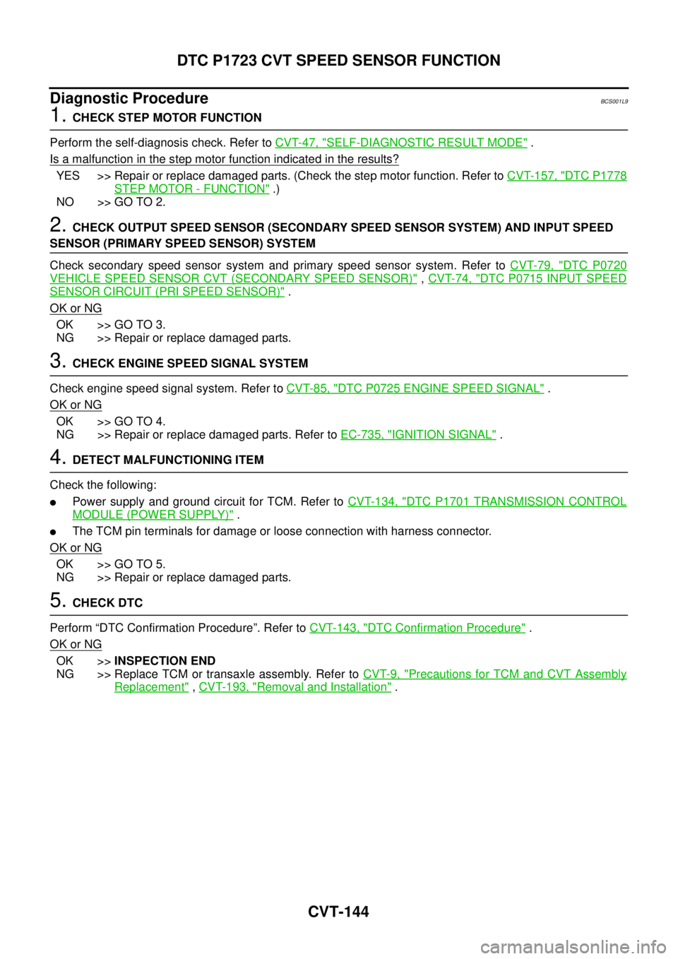
1. CHECK STEP MOTOR FUNCTION
Perform the self-diagnosis check. Refer to CVT-47, "
SELF-DIAGNOSTIC RESULT MODE" .
Is a malfunction in the step motor function indicated in the results?
YES >> Repair or replace damaged parts. (Check the step motor function. Refer to CVT-157, "DTC P1778
STEP MOTOR - FUNCTION" .)
NO >> GO TO 2.
2. CHECK OUTPUT SPEED SENSOR (SECONDARY SPEED SENSOR SYSTEM) AND INPUT SPEED
SENSOR (PRIMARY SPEED SENSOR) SYSTEM
Check secondary speed sensor system and primary speed sensor system. Refer to CVT-79, "
DTC P0720
VEHICLE SPEED SENSOR CVT (SECONDARY SPEED SENSOR)" , CVT-74, "DTC P0715 INPUT SPEED
SENSOR CIRCUIT (PRI SPEED SENSOR)" .
OK or NG
OK >> GO TO 3.
NG >> Repair or replace damaged parts.
3. CHECK ENGINE SPEED SIGNAL SYSTEM
Check engine speed signal system. Refer to CVT-85, "
DTC P0725 ENGINE SPEED SIGNAL" .
OK or NG
OK >> GO TO 4.
NG >> Repair or replace damaged parts. Refer to EC-735, "
IGNITION SIGNAL" .
4. DETECT MALFUNCTIONING ITEM
Check the following:
�Power supply and ground circuit for TCM. Refer to CVT-134, "DTC P1701 TRANSMISSION CONTROL
MODULE (POWER SUPPLY)" .
�The TCM pin terminals for damage or loose connection with harness connector.
OK or NG
OK >> GO TO 5.
NG >> Repair or replace damaged parts.
5. CHECK DTC
Perform “DTC Confirmation Procedure”. Refer to CVT-143, "
DTC Confirmation Procedure" .
OK or NG
OK >>INSPECTION END
NG >> Replace TCM or transaxle assembly. Refer to CVT-9, "
Precautions for TCM and CVT Assembly
Replacement" , CVT-193, "Removal and Installation" .
Page 1151 of 3502
DTC P1726 ELECTRIC THROTTLE CONTROL SYSTEM
CVT-145
D
E
F
G
H
I
J
K
L
MA
B
CVT
DTC P1726 ELECTRIC THROTTLE CONTROL SYSTEMPFP:23710
DescriptionBCS001LA
Electric throttle control actuator consists of throttle control motor, accelerator pedal position sensor, throttle
position sensor etc. The actuator sends a signal to the ECM, and ECM sends the signal to TCM with CAN
communication.
On Board Diagnosis LogicBCS001LB
Diagnostic trouble code “P1726 ELEC TH CONTROL” with CONSULT-II is detected when the electronically
controlled throttle for ECM is malfunctioning.
Possible CauseBCS001LC
Harness or connectors
(Sensor circuit is open or shorted.)
DTC Confirmation ProcedureBCS001LD
NOTE:
If “DTC Confirmation Procedure” has been previously performed, always turn ignition switch OFF and
wait at least 10 seconds before performing the next test.
After the repair, touch “ERASE” on “SELF-DIAG RESULTS” and then perform the following procedure to con-
firm the malfunction is eliminated.
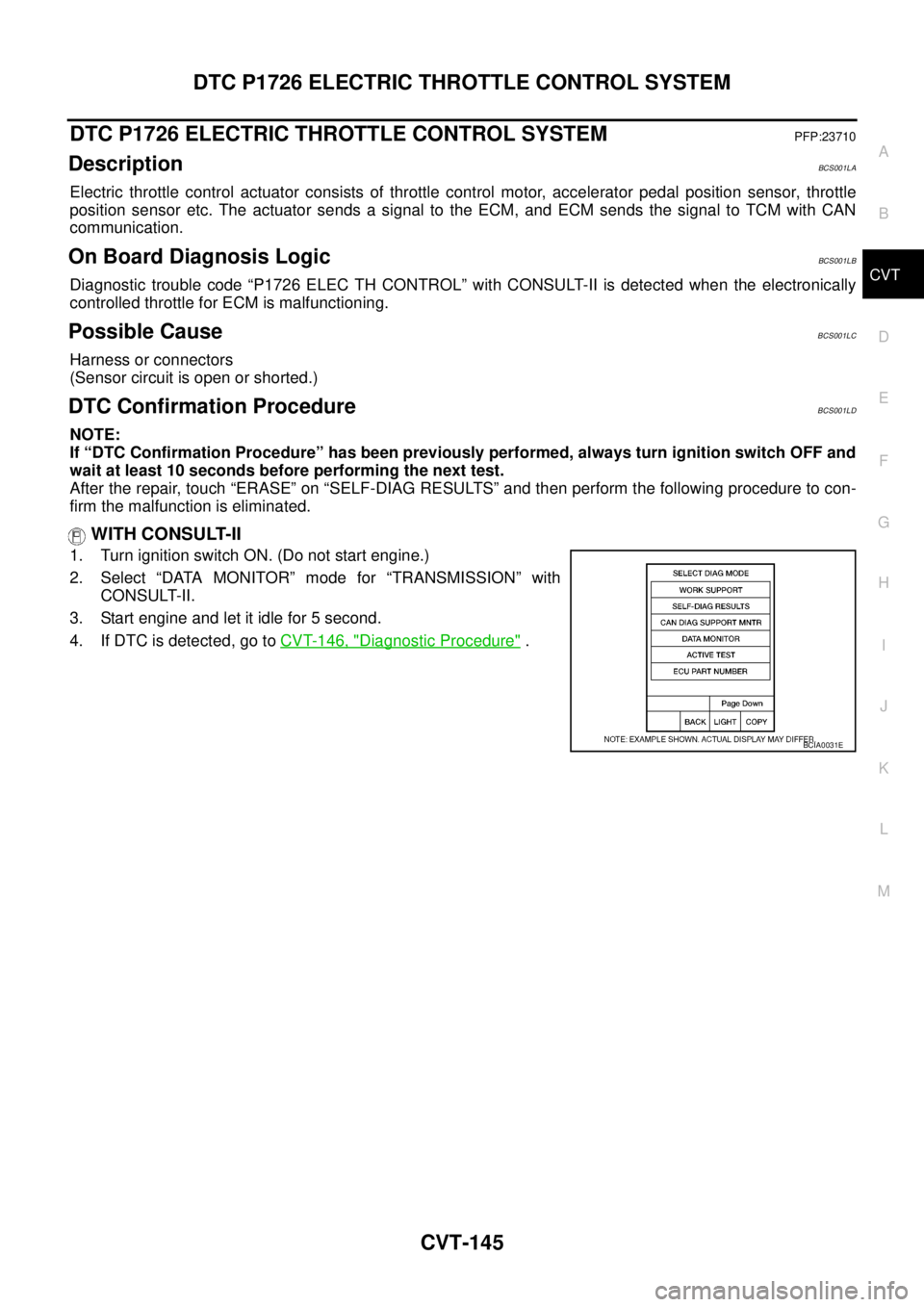
WITH CONSULT-II
1. Turn ignition switch ON. (Do not start engine.)
2. Select “DATA MONITOR” mode for “TRANSMISSION” with
CONSULT-II.
3. Start engine and let it idle for 5 second.
4. If DTC is detected, go to CVT-146, "
Diagnostic Procedure" .
BCIA0031E
Page 1158 of 3502
CVT-152
DTC P1745 LINE PRESSURE CONTROL
DTC P1745 LINE PRESSURE CONTROLPFP:31036
DescriptionBCS001LN
The pressure control solenoid valve A (line pressure solenoid valve) regulates the oil pump discharge pres-
sure to suit the driving condition in response to a signal sent from the TCM.
On Board Diagnosis LogicBCS001LO
Diagnostic trouble code “P1745 L/PRESS CONTROL” with CONSULT-II is detected when TCM detects the
unexpected line pressure.
Possible CauseBCS001LP
TCM
DTC Confirmation ProcedureBCS001LQ
NOTE:
If “DTC Confirmation Procedure” has been previously performed, always turn ignition switch OFF and
wait at least 10 seconds before performing the next test.
After the repair, touch “ERASE” on “SELF-DIAG RESULTS” and then perform the following procedure to con-
firm the malfunction is eliminated.
WITH CONSULT-II
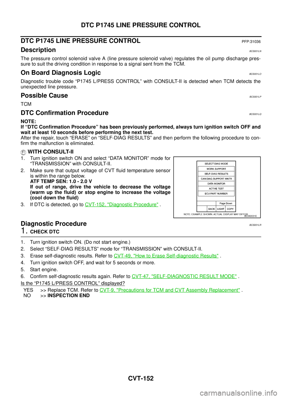
1. Turn ignition switch ON and select “DATA MONITOR” mode for
“TRANSMISSION” with CONSULT-II.
2. Make sure that output voltage of CVT fluid temperature sensor
is within the range below.
ATF TEMP SEN: 1.0 - 2.0 V
If out of range, drive the vehicle to decrease the voltage
(warm up the fluid) or stop engine to increase the voltage
(cool down the fluid)
3. If DTC is detected, go to CVT-152, "
Diagnostic Procedure" .
Diagnostic ProcedureBCS001LR
1. CHECK DTC
1. Turn ignition switch ON. (Do not start engine.)
2. Select “SELF-DIAG RESULTS” mode for “TRANSMISSION” with CONSULT-II.
3. Erase self-diagnostic results. Refer to CVT-49, "
How to Erase Self-diagnostic Results" .
4. Turn ignition switch OFF, and wait for 5 seconds or more.
5. Start engine.
6. Confirm self-diagnostic results again. Refer to CVT-47, "
SELF-DIAGNOSTIC RESULT MODE" .
Is the
“P1745 L/PRESS CONTROL” displayed?
YES >> Replace TCM. Refer to CVT-9, "Precautions for TCM and CVT Assembly Replacement" .
NO >>INSPECTION END
BCIA0031E
Page 1163 of 3502
DTC P1778 STEP MOTOR - FUNCTION
CVT-157
D
E
F
G
H
I
J
K
L
MA
B
CVT
DTC P1778 STEP MOTOR - FUNCTIONPFP:31947
DescriptionBCS001M0
�The step motor's 4 aspects of ON/OFF change according to the signal from TCM. As a result, the flow of
line pressure to primary pulley is changed and pulley ratio is controlled.
�This diagnosis item is detected when electrical system is OK, but mechanical system is NG.
�This diagnosis item is detected when the state of the changing the speed mechanism in unit does not
operate normally.
CONSULT-II Reference ValueBCS001M1
Remarks: Specification data are reference values.
On Board Diagnosis LogicBCS001M2
Diagnostic trouble code “P1778 STEP MOTR/FNC” with CONSULT-II is detected under the following condi-
tions.
�When not changing the pulley ratio according to the instruction of TCM.
Possible CauseBCS001M3
Ste p mo to r
DTC Confirmation ProcedureBCS001M4
CAUTION:
�Always drive vehicle at a safe speed.
�Before starting “DTC Confirmation Procedure”, confirm “Hi” or “Mid” or “Low” fixation by “PRI
SPEED” and “VEHICLE SPEED” on “DATA MONITOR MODE”.
�If hi-geared fixation occurred, go to CVT-158, "Diagnostic Procedure" .
NOTE:
If “DTC Confirmation Procedure” has been previously performed, always turn ignition switch OFF and
wait at least 10 seconds before performing the next test.
After the repair, touch “ERASE” on “SELF-DIAG RESULTS” and then perform the following procedure to con-
firm the malfunction is eliminated.
WITH CONSULT-II
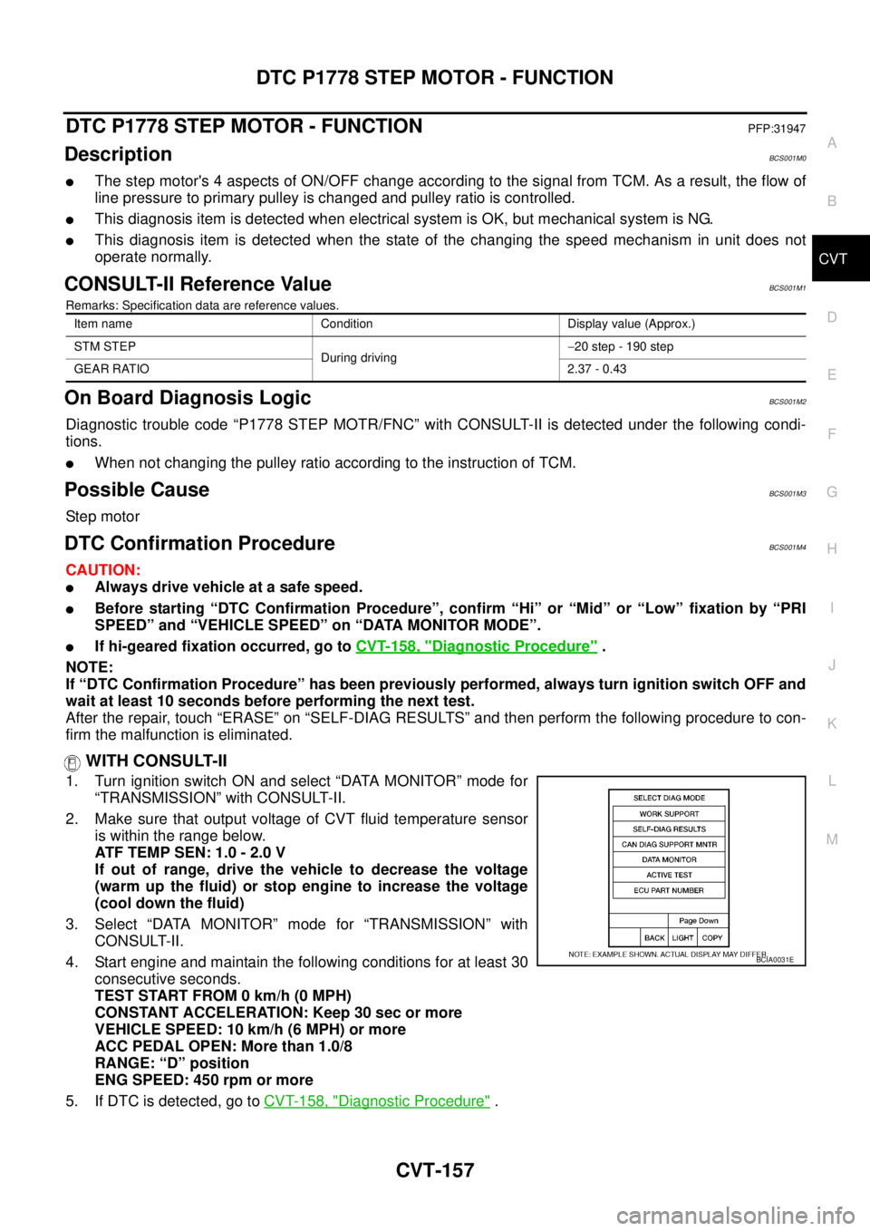
1. Turn ignition switch ON and select “DATA MONITOR” mode for
“TRANSMISSION” with CONSULT-II.
2. Make sure that output voltage of CVT fluid temperature sensor
is within the range below.
ATF TEMP SEN: 1.0 - 2.0 V
If out of range, drive the vehicle to decrease the voltage
(warm up the fluid) or stop engine to increase the voltage
(cool down the fluid)
3. Select “DATA MONITOR” mode for “TRANSMISSION” with
CONSULT-II.
4. Start engine and maintain the following conditions for at least 30
consecutive seconds.
TEST START FROM 0 km/h (0 MPH)
CONSTANT ACCELERATION: Keep 30 sec or more
VEHICLE SPEED: 10 km/h (6 MPH) or more
ACC PEDAL OPEN: More than 1.0/8
RANGE: “D” position
ENG SPEED: 450 rpm or more
5. If DTC is detected, go to CVT-158, "
Diagnostic Procedure" .
Item name Condition Display value (Approx.)
STM STEP
During driving−20 step - 190 step
GEAR RATIO2.37 - 0.43
BCIA0031E
Page 1169 of 3502
TROUBLE DIAGNOSIS FOR SYMPTOMS
CVT-163
D
E
F
G
H
I
J
K
L
MA
B
CVT
TCM terminal data are reference values, measured between each terminal and ground.
TerminalWire
colorItem Condition Data (Approx.)
5 L CAN-H — —
6 P CAN-L — —
8GBack-up lamp
relaySelector lever in “R” position. 0 V
Selector lever in other positions. Battery voltage
13 G/W ROM assembly — —
14 L/R ROM assembly — —
15 BR/R ROM assembly — —
31 O K-LINE — —
42 W/R Sensor ground Always 0 V
46 L/O Sensor power— 5.0 V
—0 V
Page 1196 of 3502
CVT-190
CVT FLUID COOLER SYSTEM
REMOVAL
WARNING:
Never remove the radiator cap when the engine is hot. Serious burns could occur from high pressure
engine coolant escaping from the radiator.
1. Remove engine undercover.
2. Drain engine coolant. Refer to CO-34, "
Changing Engine Coolant" .
CAUTION:
Perform when the engine is cold.
3. Remove air duct (inlet). Refer to EM-131, "
Removal and Installation" .
4. Remove battery. Refer to SC-13, "
Removal and Installation" .
5. Remove air cleaner case (upper and lower), resonator, mass air flow sensor and air duct assembly. Refer
to EM-131, "
Removal and Installation" .
6. Remove fuse and fusible link block from battery bracket.
7. Remove battery bracket.
8. Remove battery bracket mounting.
SCIA2749E
SCIA2750E
SCIA2751E
Page 1201 of 3502
TRANSAXLE ASSEMBLY
CVT-195
D
E
F
G
H
I
J
K
L
MA
B
CVT
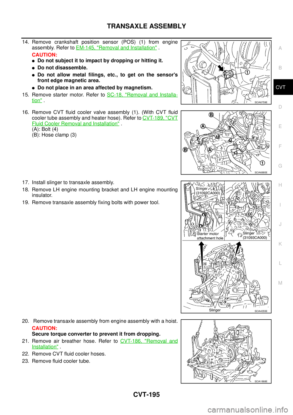
14. Remove crankshaft position sensor (POS) (1) from engine
assembly. Refer to EM-145, "
Removal and Installation" .
CAUTION:
�Do not subject it to impact by dropping or hitting it.
�Do not disassemble.
�Do not allow metal filings, etc., to get on the sensor's
front edge magnetic area.
�Do not place in an area affected by magnetism.
15. Remove starter motor. Refer to SC-18, "
Removal and Installa-
tion" .
16. Remove CVT fluid cooler valve assembly (1). (With CVT fluid
cooler tube assembly and heater hose). Refer to CVT-189, "
CVT
Fluid Cooler Removal and Installation" .
(A): Bolt (4)
(B): Hose clamp (3)
17. Install slinger to transaxle assembly.
18. Remove LH engine mounting bracket and LH engine mounting
insulator.
19. Remove transaxle assembly fixing bolts with power tool.
20. Remove transaxle assembly from engine assembly with a hoist.
CAUTION:
Secure torque converter to prevent it from dropping.
21. Remove air breather hose. Refer to CVT-186, "
Removal and
Installation" .
22. Remove CVT fluid cooler hoses.
23. Remove fluid cooler tube.
SCIA6759E
SCIA6880E
SCIA4355E
SCIA1868E
Page 1203 of 3502
TRANSAXLE ASSEMBLY
CVT-197
D
E
F
G
H
I
J
K
L
MA
B
CVT
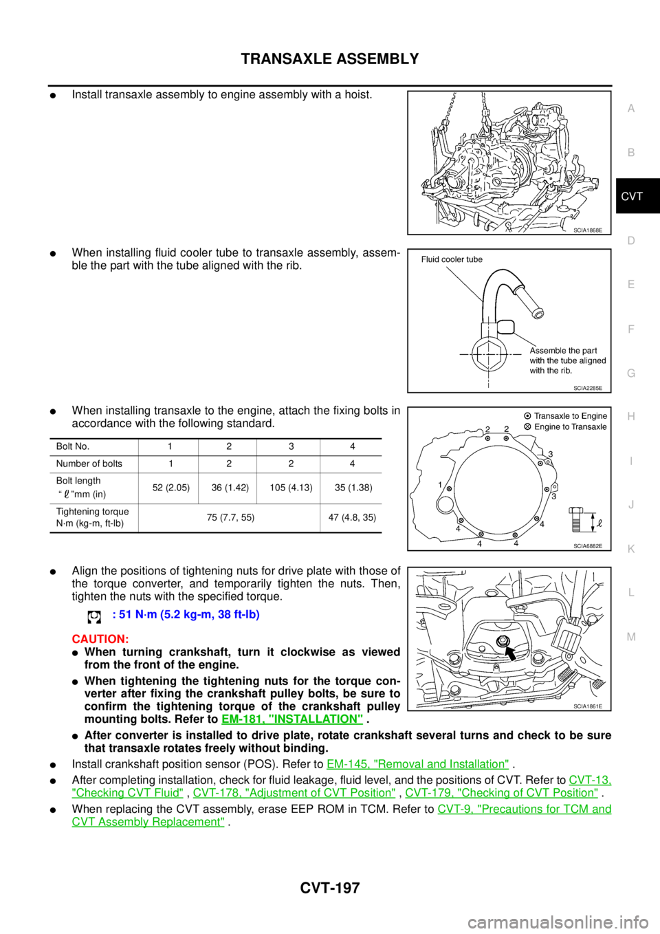
�Install transaxle assembly to engine assembly with a hoist.
�When installing fluid cooler tube to transaxle assembly, assem-
ble the part with the tube aligned with the rib.
�When installing transaxle to the engine, attach the fixing bolts in
accordance with the following standard.
�Align the positions of tightening nuts for drive plate with those of
the torque converter, and temporarily tighten the nuts. Then,
tighten the nuts with the specified torque.
CAUTION:
�When turning crankshaft, turn it clockwise as viewed
from the front of the engine.
�When tightening the tightening nuts for the torque con-
verter after fixing the crankshaft pulley bolts, be sure to
confirm the tightening torque of the crankshaft pulley
mounting bolts. Refer to EM-181, "
INSTALLATION" .
�After converter is installed to drive plate, rotate crankshaft several turns and check to be sure
that transaxle rotates freely without binding.
�Install crankshaft position sensor (POS). Refer to EM-145, "Removal and Installation" .
�After completing installation, check for fluid leakage, fluid level, and the positions of CVT. Refer to CVT-13,
"Checking CVT Fluid" , CVT-178, "Adjustment of CVT Position" , CVT-179, "Checking of CVT Position" .
�When replacing the CVT assembly, erase EEP ROM in TCM. Refer to CVT-9, "Precautions for TCM and
CVT Assembly Replacement" .
SCIA1868E
SCIA2285E
Bolt No. 1 2 3 4
Number of bolts 1 2 2 4
Bolt length
“ ”mm (in) 52 (2.05) 36 (1.42) 105 (4.13) 35 (1.38)
Tightening torque
N·m (kg-m, ft-lb)75 (7.7, 55) 47 (4.8, 35)
SCIA6882E
: 51 N·m (5.2 kg-m, 38 ft-lb)
SCIA1861E