Page 1685 of 3502
![NISSAN TEANA 2003 Service Manual TROUBLE DIAGNOSIS
EC-403
[VQ]
C
D
E
F
G
H
I
J
K
L
MA
EC
1 - 6: The numbers refer to the order of inspection.
(continued on next page)
SYSTEM — ENGINE MECHANICAL & OTHER
Intake valve timing control](/manual-img/5/57392/w960_57392-1684.png "NISSAN TEANA 2003 Service Manual TROUBLE DIAGNOSIS
EC-403
[VQ]
C
D
E
F
G
H
I
J
K
L
MA
EC
1 - 6: The numbers refer to the order of inspection.
(continued on next page)
SYSTEM — ENGINE MECHANICAL & OTHER
Intake valve timing control")
TROUBLE DIAGNOSIS
EC-403
[VQ]
C
D
E
F
G
H
I
J
K
L
MA
EC
1 - 6: The numbers refer to the order of inspection.
(continued on next page)
SYSTEM — ENGINE MECHANICAL & OTHER
Intake valve timing control solenoid valve cir-
cuit32 13223 3EC-545
PNP switch circuit 3 3 3 3 3EC-614
VIAS control solenoid valve circuit 1EC-753
Refrigerant pressure sensor circuit 2 3 3 4EC-748
Electrical load signal circuit 3EC-670
Air conditioner circuit 223333333 3 2AT C - 3 4
ABS actuator and electric unit (control unit) 4BRC-8 or
BRC-44
SYMPTOM
Refer-
ence page
HARD/NO START/RESTART (EXCP. HA)
ENGINE STALL
HESITATION/SURGING/FLAT SPOT
SPARK KNOCK/DETONATION
LACK OF POWER/POOR ACCELERATION
HIGH IDLE/LOW IDLE
ROUGH IDLE/HUNTING
IDLING VIBRATION
SLOW/NO RETURN TO IDLE
OVERHEATS/WATER TEMPERATURE HIGH
EXCESSIVE FUEL CONSUMPTION
EXCESSIVE OIL CONSUMPTION
BATTERY DEAD (UNDER CHARGE)
Warranty symptom code AA AB AC AD AE AF AG AH AJ AK AL AM HA
SYMPTOM
Reference
page
HARD/NO START/RESTART (EXCP. HA)
ENGINE STALL
HESITATION/SURGING/FLAT SPOT
SPARK KNOCK/DETONATION
LACK OF POWER/POOR ACCELERATION
HIGH IDLE/LOW IDLE
ROUGH IDLE/HUNTING
IDLING VIBRATION
SLOW/NO RETURN TO IDLE
OVERHEATS/WATER TEMPERATURE HIGH
EXCESSIVE FUEL CONSUMPTION
EXCESSIVE OIL CONSUMPTION
BATTERY DEAD (UNDER CHARGE)
Warranty symptom code AA AB AC AD AE AF AG AH AJ AK AL AM HA
Fuel Fuel tank
5
5FL-8
Fuel piping 5 5 5 5 5 5FL-3
Vapor lock—
Valve deposit
5 555 55 5—
Poor fuel (Heavy weight gaso-
line, Low octane)—
Page 2191 of 3502
![NISSAN TEANA 2003 Service Manual CYLINDER BLOCK
EM-83
[QR]
C
D
E
F
G
H
I
J
K
L
MA
EM
�A widely use engine stand can be used.
CAUTION:
Use engine stand that has a load capacity [approximately
150 kg (331 lb) or more] large enough fo](/manual-img/5/57392/w960_57392-2190.png "NISSAN TEANA 2003 Service Manual CYLINDER BLOCK
EM-83
[QR]
C
D
E
F
G
H
I
J
K
L
MA
EM
�A widely use engine stand can be used.
CAUTION:
Use engine stand that has a load capacity [approximately
150 kg (331 lb) or more] large enough fo")
CYLINDER BLOCK
EM-83
[QR]
C
D
E
F
G
H
I
J
K
L
MA
EM
�A widely use engine stand can be used.
CAUTION:
Use engine stand that has a load capacity [approximately
150 kg (331 lb) or more] large enough for supporting the
engine weight.
NOTE:
This example is an engine stand for holding at transaxle
mounting side with drive plate removed.
3. Drain engine oil. Refer to LU-9, "
Changing Engine Oil" .
4. Drain engine coolant by removing water drain plug from inside of
engine.
5. Remove cylinder head. Refer to EM-65, "
CYLINDER HEAD" .
6. Remove knock sensor.
CAUTION:
Carefully handle knock sensor avoiding shocks.
7. Remove crankshaft position sensor (POS).
CAUTION:
�Avoid impacts such as a dropping.
�Do not disassemble.
�Keep it away from metal particles.
�Do not place sensor in a location where it is exposed to
magnetism.
8. Remove drive plate.
�Secure drive plate with stopper plate, and remove mounting
bolts.
NOTE:
Use TORX socket (size E20).
CAUTION:
Be careful not to damage or scratch drive plate.
PBIC0085E
PBIC2443E
PBIC2191E
PBIC2352E
Page 2338 of 3502
![NISSAN TEANA 2003 Service Manual EM-230
[VQ]
CYLINDER BLOCK
�A widely use engine stand can be used.
CAUTION:
Use engine stand that has a load capacity [approximately
220 kg (441 lb) or more] large enough for supporting the
engine w](/manual-img/5/57392/w960_57392-2337.png "NISSAN TEANA 2003 Service Manual EM-230
[VQ]
CYLINDER BLOCK
�A widely use engine stand can be used.
CAUTION:
Use engine stand that has a load capacity [approximately
220 kg (441 lb) or more] large enough for supporting the
engine w")
EM-230
[VQ]
CYLINDER BLOCK
�A widely use engine stand can be used.
CAUTION:
Use engine stand that has a load capacity [approximately
220 kg (441 lb) or more] large enough for supporting the
engine weight.
NOTE:
This example is engine stand for holding at transaxle mount-
ing side with drive plate removed.
5. Drain engine oil. Refer to LU-21, "
Changing Engine Oil" .
6. Drain engine coolant by removing water drain plugs from cylin-
der block both sides at “A” and “D” and cylinder block front side
at “B” as shown in the figure.
NOTE:
Water drain plug at the right bank side for VQ35DE is also used
as a connector of water pipe for oil cooler. Refer to LU-23, "
OIL
COOLER (VQ35DE)" .
7. Remove drive plate. Fix crankshaft pulley with pulley holder [SST: KV10109300], and remove mounting
bolts.
�Loosen mounting bolts in diagonal order.
CAUTION:
�Do not disassemble drive plate.
�Do not place drive plate with signal plate facing down.
�When handling signal plate, take care not to damage or
scratch it.
�Handle signal plate in a manner that prevents it from
becoming magnetized.
8. Remove cylinder head. Refer to EM-210, "
CYLINDER HEAD" .
9. Remove knock sensor.
CAUTION:
Carefully handle sensor avoiding shocks.
PBIC0085E
PBIC2487E
SEM760G
Page 2424 of 3502

FL-8
FUEL TANK
FUEL TANKPFP:17202
Removal and InstallationBBS005AI
REMOVAL
WARNING:
Be sure to read “General Precautions” before working on the fuel system. Refer to FL-3, "
General Pre-
cautions" .
�Drain fuel from fuel tank if necessary. Refer to FL-4, "REMOVAL" .
CAUTION:
For the safety work and to maintain fuel tank gravity at center, drain fuel to the level where fuel
tank weight at left and right becomes equal.
�Perform work on level place.
1. Perform steps 2 to 7 of “REMOVAL” in “FUEL LEVEL SENSOR UNIT, FUEL FILTER AND FUEL PUMP
ASSEMBLY”. Refer to FL-4, "
REMOVAL" .
2. Remove center muffler. Refer to EX-2, "
EXHAUST SYSTEM" .
3. Remove center muffler mounting rubber. Refer to EX-2, "
EXHAUST SYSTEM" .
4. Move parking brake rear right and left cables from the lower part of fuel tank. Refer to PB-3, "
PA R K I N G
BRAKE CONTROL" .
5. Support bottom of rear suspension member with transmission jack, and descend rear suspension assem-
bly. Refer to RSU-5, "
REAR SUSPENSION ASSEMBLY" .
6. Remove fuel tank protector.
1. Fuel filler tube 2. Vent hose 3. Fuel tank
4. Fuel tank mounting band 5. Clip 6. Fuel tank protector
7. Fuel tank mounting band 8. Fuel filler hose 9. Grommet
10. Fuel filler cap 11. EVAP hose
PBIC2527E
Page 2450 of 3502

GI-4
PRECAUTIONS
Precautions Necessary for Steering Wheel Rotation After Battery DisconnectBAS00072
NOTE:
�This Procedure is applied only to models with Intelligent Key system and NATS (NISSAN ANTI-THEFT
SYSTEM).
�Remove and install all control units after disconnecting both battery cables with the ignition knob in the
″LOCK″ position.
�Always use CONSULT-II to perform self-diagnosis as a part of each function inspection after finishing
work. If DTC is detected, perform trouble diagnosis according to self-diagnostic results.
For models equipped with the Intelligent Key system and NATS, an electrically controlled steering lock mech-
anism is adopted on the key cylinder.
For this reason, if the battery is disconnected or if the battery is discharged, the steering wheel will lock and
steering wheel rotation will become impossible.
If steering wheel rotation is required when battery power is interrupted, follow the procedure below before
starting the repair operation.
OPERATION PROCEDURE
1. Connect both battery cables.
NOTE:
Supply power using jumper cables if battery is discharged.
2. Use the Intelligent Key or mechanical key to turn the ignition switch to the ″ACC″ position. At this time, the
steering lock will be released.
3. Disconnect both battery cables. The steering lock will remain released and the steering wheel can be
rotated.
4. Perform the necessary repair operation.
5. When the repair work is completed, return the ignition switch to the ″LOCK″ position before connecting
the battery cables. (At this time, the steering lock mechanism will engage.)
6. Perform a self-diagnosis check of all control units using CONSULT-II.
General PrecautionsBAS00073
�Do not operate the engine for an extended period of time without
proper exhaust ventilation.
Keep the work area well ventilated and free of any flammable
materials. Special care should be taken when handling any flam-
mable or poisonous materials, such as gasoline, refrigerant gas,
etc. When working in a pit or other enclosed area, be sure to
properly ventilate the area before working with hazardous mate-
rials.
Do not smoke while working on the vehicle.
�Before jacking up the vehicle, apply wheel chocks or other tire
blocks to the wheels to prevent the vehicle from moving. After
jacking up the vehicle, support the vehicle weight with safety
stands at the points designated for proper lifting before working
on the vehicle.
These operations should be done on a level surface.
�When removing a heavy component such as the engine or tran-
saxle/transmission, be careful not to lose your balance and drop
them. Also, do not allow them to strike adjacent parts, especially
the brake tubes and master cylinder.
SGI285
SGI231
Page 2466 of 3502
GI-20
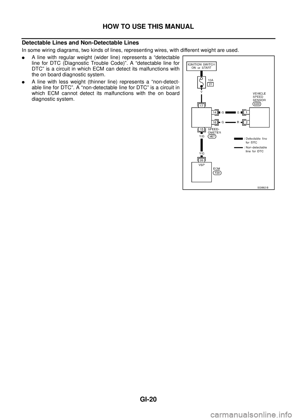
HOW TO USE THIS MANUAL
Detectable Lines and Non-Detectable Lines
In some wiring diagrams, two kinds of lines, representing wires, with different weight are used.
�A line with regular weight (wider line) represents a “detectable
line for DTC (Diagnostic Trouble Code)”. A “detectable line for
DTC” is a circuit in which ECM can detect its malfunctions with
the on board diagnostic system.
�A line with less weight (thinner line) represents a “non-detect-
able line for DTC”. A “non-detectable line for DTC” is a circuit in
which ECM cannot detect its malfunctions with the on board
diagnostic system.
SGI862-B
Page 2721 of 3502
HEADLAMP - XENON TYPE -
LT-33
C
D
E
F
G
H
I
J
L
MA
B
LT
Aiming AdjustmentBKS001NF
PREPARATION BEFORE ADJUSTING
For Details, Refer To the Regulations In Your Own Country.
Before performing aiming adjustment, check the following.
1. Keep all tires inflated to correct pressures.
2. Place vehicle on level ground.
3. Set that there is no-load in vehicle other than the driver (or equivalent weight placed in driver's position).
Coolant, engine oil filled up to correct level and full fuel tank.
LOW BEAM AND HIGH BEAM
1. Turn headlamp low beam ON.
2. Use adjustment screws to perform aiming adjustment.
PKIC9406E
Page 2748 of 3502
LT-60
HEADLAMP - HALOGEN TYPE -
Aiming AdjustmentBKS001O1
PREPARATION BEFORE ADJUSTING
For Details, Refer To the Regulations In Your Own Country.
Before performing aiming adjustment, check the following.
1. Keep all tires inflated to correct pressures.
2. Place vehicle on level ground.
3. Set that there is no-load in vehicle other then the driver (or equivalent weight placed in driver’s position).
Coolant, engine oil filled up to correct level and full fuel tank.
LOW BEAM AND HIGH BEAM
1. Turn headlamp low beam ON.
CAUTION:
Be sure aiming switch is set to “0” when performing aiming adjustment.
2. Use adjustment screws to perform aiming adjustment.
PKIC9406E