Page 396 of 3502
ATC-18
PREPARATION
Commercial Service ToolsBJS000FE
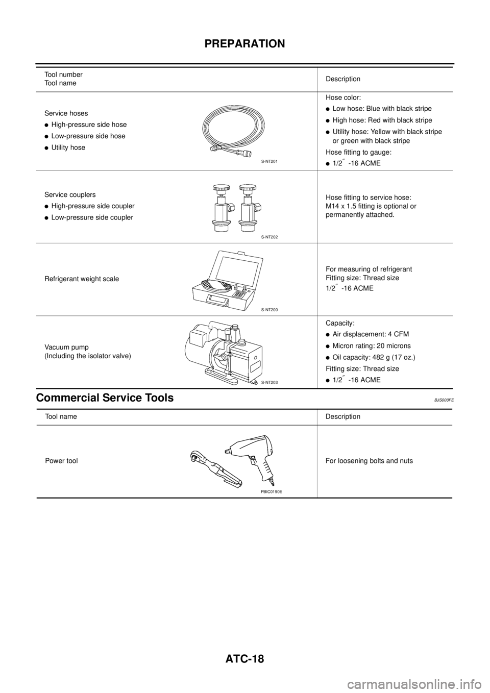
Service hoses
�High-pressure side hose
�Low-pressure side hose
�Utility hoseHose color:
�Low hose: Blue with black stripe
�High hose: Red with black stripe
�Utility hose: Yellow with black stripe
or green with black stripe
Hose fitting to gauge:
�1/2″ -16 ACME
Service couplers
�High-pressure side coupler
�Low-pressure side couplerHose fitting to service hose:
M14 x 1.5 fitting is optional or
permanently attached.
Refrigerant weight scaleFor measuring of refrigerant
Fitting size: Thread size
1/2
″ -16 ACME
Vacuum pump
(Including the isolator valve)Capacity:
�Air displacement: 4 CFM
�Micron rating: 20 microns
�Oil capacity: 482 g (17 oz.)
Fitting size: Thread size
�1/2″ -16 ACME Tool number
Tool nameDescription
S-NT201
S-NT202
S-NT200
S-NT203
Tool nameDescription
Power toolFor loosening bolts and nuts
PBIC0190E
Page 672 of 3502

BL-14
HOOD
SURFACE HEIGHT ADJUSTMENT
1. Remove hood lock, and adjust the surface height difference of hood, fender and headlamp according to
the fitting standard dimension, by rotating RH and LH bumper rubbers.
2. Install hood lock temporarily, and move hood lock laterally until the centers of striker and lock become ver-
tical when viewed from the front.
3. Check that the hood lock secondary latch is properly engaged
with the secondary striker with hood's own weight.
4. Check that the hood lock primary latch is securely engaged with
the hood striker with hood's own weight by dropping hood from
approx. 200 mm (7.87) height.
CAUTION:
Do not drop hood from a height of 300 mm (11.81 in) or
more.
5. Move hood lockup and down until striker smoothly engages the
lock when the hood is closed.
6. When pulling the hood opener lever gently, make sure that front
end of the hood rises by approximately 20 mm (0.79) and that hood striker and hood lock primary latch is
disengaged. Also make sure that hood opener returns to the original position.
7. After adjustment, tighten lock bolts to the specified torque.
Removal and InstallationBIS000VQ
Hood (B) - Headlamp (B) : 0.75 ± 1.8 mm (0.030 ± 0.071 in)
Hood (C) - fender (C) : 0 ± 1.0 mm (0 ± 0.039 in)
PIIB0259E
1. Hood assembly 2. Hood stay 3. Hood hinge
4. Hood lock 5. Washer hose 6. Hood insulator
7. Radiator core seal rubber
PIIB0260E
Page 673 of 3502
HOOD
BL-15
C
D
E
F
G
H
J
K
L
MA
B
BL
REMOVAL
Hood Assembly
1. Support the hood striker with a proper material to prevent it from
falling.
WARNING:
Body injury may occur if no supporting rod is holding the
hood open when removing the hood stay.
2. Disconnect washer hose at the connecting point.
3. Remove the hood stays from the stud balls on the body side.
4. Remove hinge nuts on hood and remove hood assembly.
CAUTION:
Operate with two workers, because of its heavy weight.
INSTALLATION
�Install in the reverse order of removal.
�Apply Anti-Corrosion or equivalent to the attaching portion of hood hinge, hood ledge, and hood assembly.
�After installing, perform hood fitting adjustment. Refer to BL-13, "Fitting Adjustment" .
PIIB0261E
: 12.7 N·m (1.3 kg-m, 9 ft-lb)
PIIB0262E
Page 675 of 3502

HOOD
BL-17
C
D
E
F
G
H
J
K
L
MA
B
BL
4. Install cable securely to the lock.
5. After installing, check hood lock adjustment and hood opener
operation.
6. After installing, perform hood fitting adjustment. Refer to BL-13,
"Fitting Adjustment" .
Hood Lock Control InspectionBIS000VS
CAUTION:
If the hood lock cable is bent or deformed, replace it.
1. Make sure that the hood lock secondary latch is properly
engaged with the secondary striker with hood's own weight.
2. Make sure that the hood lock primary latch is securely engaged
with the hood striker with hood's own weight by dropping it from
approx. 200 mm (7.87 in) height.
CAUTION:
Do not drop hood from a height of 300 mm (11.81) or more.
3. When pulling hood opener lever gently, make sure that front end of the hood rises by approximately 20
mm (0.79in) and that hood striker and hood lock primary latch are disengaged. Also make sure that hood
opener returns to the original position.
4. Confirm hood lock is properly lubricated. If necessary, apply
grease at the point shown in the figure.
PIIB1755E
PIIB0259E
PIIB1334E
Page 778 of 3502

BL-120
DOOR
STRIKER ADJUSTMENT
Adjust the striker so that it becomes parallel with the lock insertion
direction.
Removal and Installation of Front DoorBIS000XS
CAUTION:
�When removing and installing the front door assembly, support the door with a jack and cloth to
protect the door and body.
�When removing and installing front door assembly, be sure to perform the fitting adjustment Refer
to BL-119, "
Fitting Adjustment" .
�Operate with two workers, because of its heavy weight.
�Check the hinge rotating part for poor lubrication. If necessary, apply “body grease”.
�After installing, check operation.
REMOVAL
1. Disconnect the front door harness connector.
2. Remove the mounting bolts of the check link on the vehicle.
3. Remove the door-side hinge mounting nuts, and remove the
door assembly.
INSTALLATION
Install in the reverse order of removal.
Removal and Installation of Rear DoorBIS000XT
CAUTION:
�When removing and installing the rear door assembly, support the door with a jack and cloth to
protect the door and body.
�When removing and installing rear door assembly, be sure to perform the fitting adjustment Refer
to BL-119, "
Fitting Adjustment" . : 16.7 N·m (1.7 kg-m, 12 ft-lb)
PIIB1226E
: 14.7 N·m (1.5 kg-m, 11 ft-lb)
PIIB1227E
: 24.5 N·m (2.5 kg-m, 18 ft-lb)
PIIB0279E
Page 779 of 3502
DOOR
BL-121
C
D
E
F
G
H
J
K
L
MA
B
BL
�Operate with two workers, because of its heavy weight.
�Check the hinge rotating part for poor lubrication. If necessary, apply “body grease”.
�After installing, check operation.
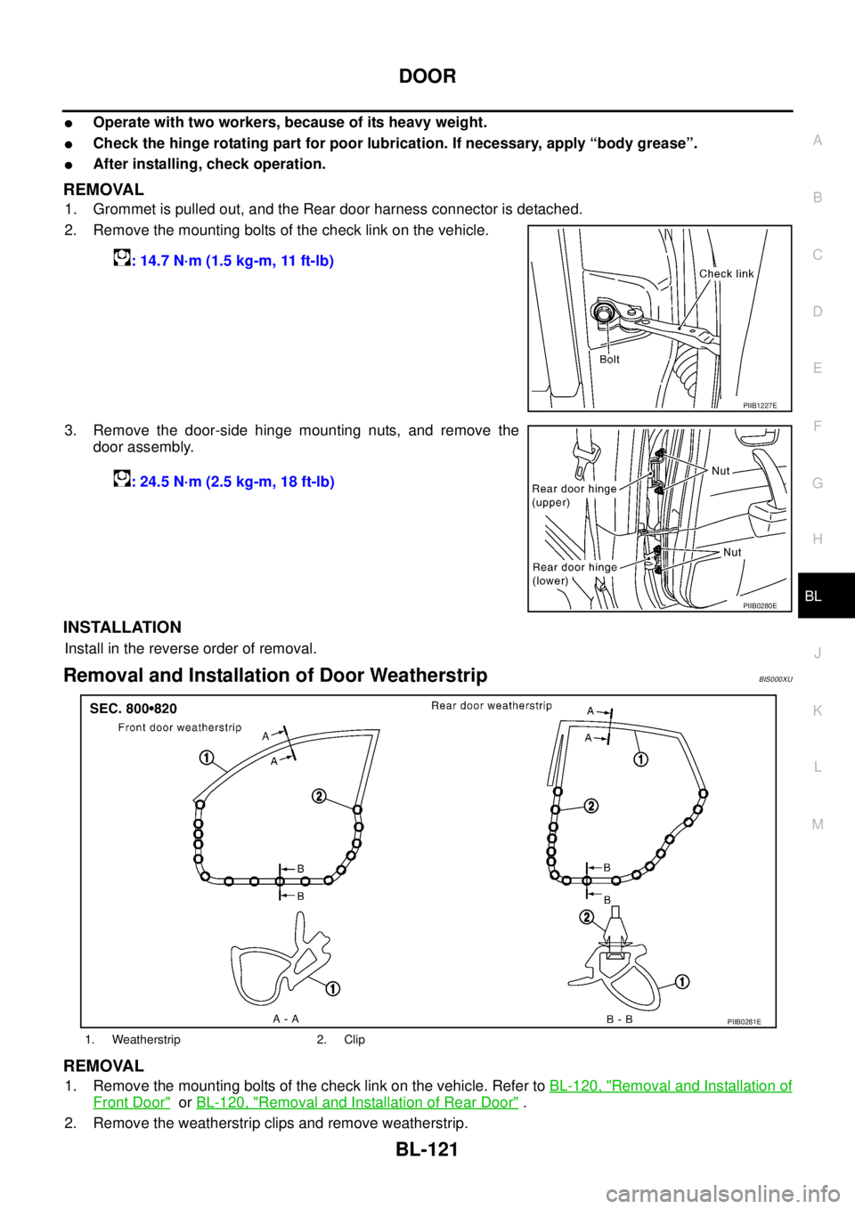
REMOVAL
1. Grommet is pulled out, and the Rear door harness connector is detached.
2. Remove the mounting bolts of the check link on the vehicle.
3. Remove the door-side hinge mounting nuts, and remove the
door assembly.
INSTALLATION
Install in the reverse order of removal.
Removal and Installation of Door WeatherstripBIS000XU
REMOVAL
1. Remove the mounting bolts of the check link on the vehicle. Refer to BL-120, "Removal and Installation of
Front Door" or BL-120, "Removal and Installation of Rear Door" .
2. Remove the weatherstrip clips and remove weatherstrip.: 14.7 N·m (1.5 kg-m, 11 ft-lb)
PIIB1227E
: 24.5 N·m (2.5 kg-m, 18 ft-lb)
PIIB0280E
1. Weatherstrip 2. Clip
PIIB0281E
Page 791 of 3502

TRUNK LID
BL-133
C
D
E
F
G
H
J
K
L
MA
B
BL
3. Remove trunk lid stay.
WARNING:
Body injury may occur if no supporting rod is holding the
trunk lid open when removing the damper stay.
4. Remove the trunk lid hinge mounting bolts, and remove the
trunk lid assembly.
CAUTION:
Operate with two workers, because of its heavy weight.
INSTALLATION
Install in the reverse order of removal.
CAUTION:
�After installing, apply touch-up paint (the body color) onto the head of the hinge mounting bolts.
�After installing, check the trunk lid adjustment. Refer to BL-131, "Fitting Adjustment" .
Trunk Lid Stay Removal and InstallationBIS000Y2
REMOVAL
1. Insert flat-bladed screwdriver into the gap and remove holder.
2. Remove trunk lid stay on the trunk lid.
3. Remove the stud bolts, and trunk lid stay.
WARNING:
Body injury may occur if no supporting rod is holding the trunk
lid open when removing the damper stay.
INSTALLATION
1. Install in the reverse order of removal.
2. After installing, check the operation.
PIIB0290E
SIIA1561E
PIIB0290E
Page 1344 of 3502
![NISSAN TEANA 2003 Service Manual EC-62
[QR]
TROUBLE DIAGNOSIS
SYSTEM — ENGINE MECHANICAL & OTHER
SYMPTOM
Reference
page
HARD/NO START/RESTART (EXCP. HA)
ENGINE STALL
HESITATION/SURGING/FLAT SPOT
SPARK KNOCK/DETONATION
LACK OF PO](/manual-img/5/57392/w960_57392-1343.png "NISSAN TEANA 2003 Service Manual EC-62
[QR]
TROUBLE DIAGNOSIS
SYSTEM — ENGINE MECHANICAL & OTHER
SYMPTOM
Reference
page
HARD/NO START/RESTART (EXCP. HA)
ENGINE STALL
HESITATION/SURGING/FLAT SPOT
SPARK KNOCK/DETONATION
LACK OF PO")
EC-62
[QR]
TROUBLE DIAGNOSIS
SYSTEM — ENGINE MECHANICAL & OTHER
SYMPTOM
Reference
page
HARD/NO START/RESTART (EXCP. HA)
ENGINE STALL
HESITATION/SURGING/FLAT SPOT
SPARK KNOCK/DETONATION
LACK OF POWER/POOR ACCELERATION
HIGH IDLE/LOW IDLE
ROUGH IDLE/HUNTING
IDLING VIBRATION
SLOW/NO RETURN TO IDLE
OVERHEATS/WATER TEMPERATURE HIGH
EXCESSIVE FUEL CONSUMPTION
EXCESSIVE OIL CONSUMPTION
BATTERY DEAD (UNDER CHARGE)
Warranty symptom code AA AB AC AD AE AF AG AH AJ AK AL AM HA
Fuel Fuel tank
5
5FL-8
Fuel piping 5 5 5 5 5 5EM-34
Vapor lock—
Valve deposit
5 555 55 5—
Poor fuel (Heavy weight gaso-
line, Low octane)—
Air Air duct
55555 5EM-17
Air cleaner
Air leakage from air duct
(Mass air flow sensor —electric
throttle control actuator)
5555
Electric throttle control actuator
EM-19
Air leakage from intake manifold/
Collector/Gasket
Cranking Battery
111111 11SC-4
Alternator circuitSC-27
Starter circuit 3SC-14
Signal plate/Flywheel/Drive plate 6EM-81
PNP switch 4AT- 1 6 1
Engine Cylinder head
55555 55 5EM-65
Cylinder head gasket 4 3
Cylinder block
66666 66 64
EM-81
Piston
Piston ring
Connecting rod
Bearing
Crankshaft
Va l v e
mecha-
nismTiming chain
55555 55 5EM-53
CamshaftEM-41
Intake valve timing controlEM-53
Intake valve
3EM-65
Exhaust valve