Page 3141 of 3502
![NISSAN TEANA 2003 Service Manual POWER STEERING GEAR AND LINKAGE
PS-27
C
D
E
F
H
I
J
K
L
MA
B
PS
16. Measure pinion rotating torque using the preload adapter [SST]
and preload gauge [SST] to make sure that the measured value
is wit](/manual-img/5/57392/w960_57392-3140.png "NISSAN TEANA 2003 Service Manual POWER STEERING GEAR AND LINKAGE
PS-27
C
D
E
F
H
I
J
K
L
MA
B
PS
16. Measure pinion rotating torque using the preload adapter [SST]
and preload gauge [SST] to make sure that the measured value
is wit")
POWER STEERING GEAR AND LINKAGE
PS-27
C
D
E
F
H
I
J
K
L
MA
B
PS
16. Measure pinion rotating torque using the preload adapter [SST]
and preload gauge [SST] to make sure that the measured value
is within the standard. Readjust if the value is outside the stan-
dard. Replace steering gear assembly if the value is outside the
standard after readjusting or adjusting screw rotating torque is 5
N·m (0.51 kg-m, 44 in-lb) or less.
17. Apply recommended Liquid Gasket to inner socket and turn pin-
ion fully to left with inner socket installed to gear housing assembly.
18. Set dial indicator as shown in the figure. Measure vertical move-
ment of rack assembly when pinion is turned clockwise with
torque of 19.6 N·m (2.0 kg-m, 14 in-lb). Readjust adjusting
screw angle if the measured value is outside the standard.
Replace gear assembly if the measured value is still outside the
standard or adjusting screw rotating torque is 5 N·m (0.51 kg-m,
44 in-lb) or less.
19. Install large end of boot to gear housing assembly.
20. Install small end of boot to inner socket boot mounting groove.
21. Install boot clamp to boot small end.
22. Install large side of boot clamp.
�Tighten large side of boot with boot clamp (stainless wire).
�Wrap clamp around boot groove for two turns. Insert a flat-
bladed screwdriver in loops on both ends of wire. Twist 4 to
4.5 turns while pulling them with force of approximately 98 N
(10 kg, 22 lb).
Pinion rotating torque standard
Around neutral position
(Within ±100°) Average A0.8 - 2.0 N·m
(0.09 - 0.20 kg-m, 7 - 17 in-lb)
Maximum variation B 2.3 N·m (0.23 kg-m, 20 in-lb)
SGIA0936E
SGIA1147E
Measuring pointRack axial direction 5 mm (0.20 in) from housing end surface
Rack radial direction Axial direction of the adjusting screw
Vertical movement of rack 0.265 mm (0.0104 in)
SGIA1325E
Wire length L : 390 mm (15.35 in)
SGIA0163E
Page 3142 of 3502
PS-28
POWER STEERING GEAR AND LINKAGE
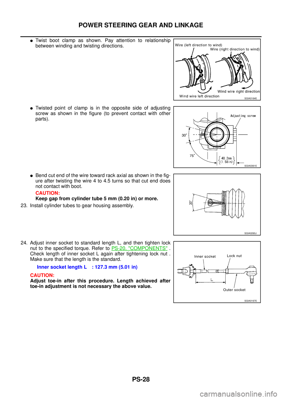
�Twist boot clamp as shown. Pay attention to relationship
between winding and twisting directions.
�Twisted point of clamp is in the opposite side of adjusting
screw as shown in the figure (to prevent contact with other
parts).
�Bend cut end of the wire toward rack axial as shown in the fig-
ure after twisting the wire 4 to 4.5 turns so that cut end does
not contact with boot.
CAUTION:
Keep gap from cylinder tube 5 mm (0.20 in) or more.
23. Install cylinder tubes to gear housing assembly.
24. Adjust inner socket to standard length L, and then tighten lock
nut to the specified torque. Refer to PS-20, "
COMPONENTS" .
Check length of inner socket L again after tightening lock nut .
Make sure that the length is the standard.
CAUTION:
Adjust toe-in after this procedure. Length achieved after
toe-in adjustment is not necessary the above value.
SGIA0164E
SGIA0361E
SGIA0260J
Inner socket length L : 127.3 mm (5.01 in)
SGIA0167E
Page 3144 of 3502

PS-30
POWER STEERING OIL PUMP
Removal and InstallationBGS0003Z
REMOVAL
1. Drain power steering fluid from reservoir tank.
2. Remove tyres from vehicle.
3. Remove side splash guard.
4. Remove heat insulator from vehicle. (Except for QR20DE mod-
els).
5. Loosen drive belt. Refer to EM-14, "
DRIVE BELTS" (QR20DE
models), EM-128, "
DRIVE BELTS" (Except for QR20DE mod-
els).
6. Remove drive belt from oil pump pulley.
7. Disconnect the pressure sensor electrical connector.
8. Remove piping of high pressure and low pressure (drain fluid
from their pipings). Refer to PS-39, "
HYDRAULIC LINE" .
9. Remove power steering oil pump mounting bolts, and then
remove power steering oil pump. Refer to PS-39, "
HYDRAULIC
LINE" .
INSTALLATION
�Installation is the reverse order of removal. For tightening torque, refer to PS-39, "HYDRAULIC LINE" .
�Perform the following procedure after installing.
–Adjust belt tension (Except for QR20DE models). Refer to EM-128, "DRIVE BELTS" .
–About the installation of QR20DE drive belt, refer to EM-14, "DRIVE BELTS" .
–Bleed air. Refer to PS-7, "Air Bleeding Hydraulic System" .
SGIA0502E
Page 3148 of 3502
PS-34
POWER STEERING OIL PUMP
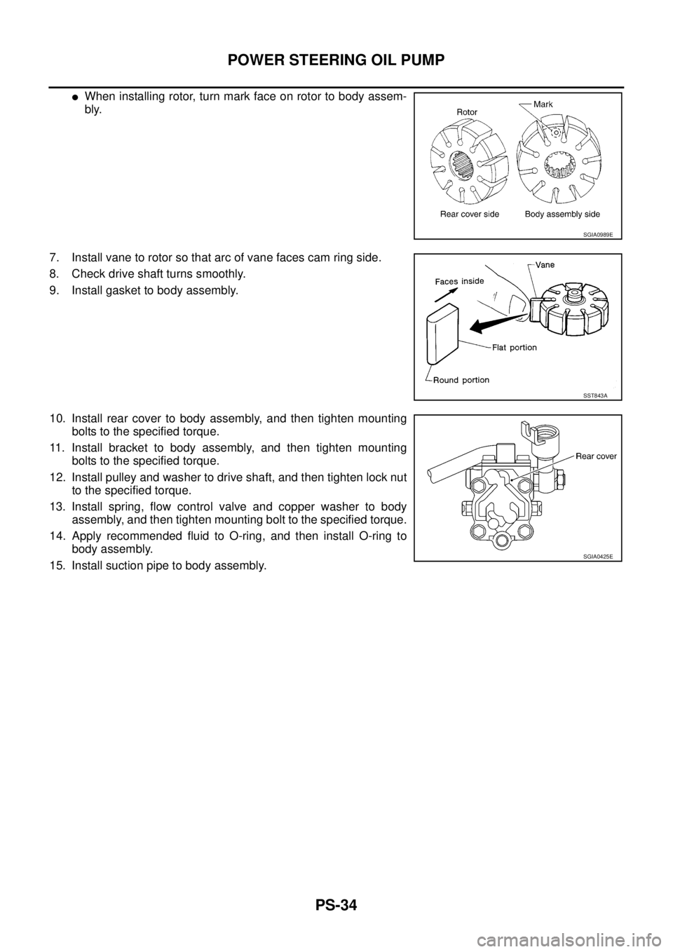
�When installing rotor, turn mark face on rotor to body assem-
bly.
7. Install vane to rotor so that arc of vane faces cam ring side.
8. Check drive shaft turns smoothly.
9. Install gasket to body assembly.
10. Install rear cover to body assembly, and then tighten mounting
bolts to the specified torque.
11. Install bracket to body assembly, and then tighten mounting
bolts to the specified torque.
12. Install pulley and washer to drive shaft, and then tighten lock nut
to the specified torque.
13. Install spring, flow control valve and copper washer to body
assembly, and then tighten mounting bolt to the specified torque.
14. Apply recommended fluid to O-ring, and then install O-ring to
body assembly.
15. Install suction pipe to body assembly.
SGIA0989E
SST843A
SGIA0425E
Page 3152 of 3502

PS-38
POWER STEERING OIL PUMP
7. Install rotor so that mark faces body assembly side, and then
install it to pulley shaft.
8. Install vane to rotor so that arc of vane faces cam ring side.
9. Install rotor snap ring to slit of pulley shaft using a hammer and a
10 mm (0.39 in) socket.
CAUTION:
�Do not damage rotor and pulley shaft.
�Power steering oil pump must be replaced if rotor is dam-
aged.
10. Install rear side plate with dowel pin A on flow control valve A
side as shown in the figure aligning with rear side plate cutout B
to cartridge.
11. Apply recommended fluid to O-ring, and then Install O-ring to
body assembly.
12. Apply recommended fluid to O-ring, and then install O-ring to
rear side plate.
13. Apply recommended fluid to Teflon ring, and then install Teflon
ring to rear side plate.
14. Install rear cover to body assembly, and then tighten mounting
bolts to the specified torque.
15. Apply recommended fluid to O-ring, and then install O-ring to body assembly.
16. Install suction pipe to body assembly.
17. Install rear bracket to rear cover, and then tighten mounting bolts to the specified torque.
18. Install front bracket to body assembly, and then tighten mounting bolts to the specified torque.
SGIA0874E
SGIA0613E
SGIA0063E
SGIA0530E
Page 3155 of 3502
HYDRAULIC LINE
PS-41
C
D
E
F
H
I
J
K
L
MA
B
PS
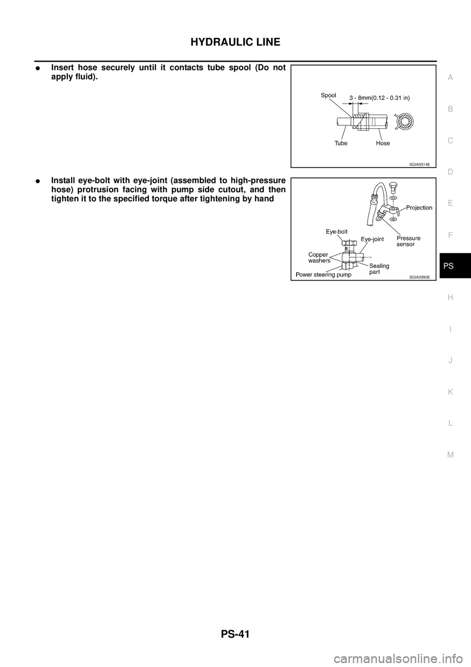
�Insert hose securely until it contacts tube spool (Do not
apply fluid).
�Install eye-bolt with eye-joint (assembled to high-pressure
hose) protrusion facing with pump side cutout, and then
tighten it to the specified torque after tightening by hand
SGIA0514E
SGIA0990E
Page 3157 of 3502

PS-43
C
D
E
F
H
I
J
K
L
MA
B
PS
Steering GearBGS00046
STEERING OUTER SOCKET AND INNER SOCKET
RACK STROKE
RACK SLIDING FORCE
Oil PumpBGS00048
Steering FluidBGS00")
SERVICE DATA AND SPECIFICATIONS (SDS)
PS-43
C
D
E
F
H
I
J
K
L
MA
B
PS
Steering GearBGS00046
STEERING OUTER SOCKET AND INNER SOCKET
RACK STROKE
RACK SLIDING FORCE
Oil PumpBGS00048
Steering FluidBGS00049
Steering gear typePR26AM
Outer socketSwinging torque 0.3 – 2.9 N·m (0.03 – 0.29 kg-m, 3 – 25 in-lb)
Measurement on spring balance
�Measuring point at cotter pin hole of stud4.84 – 46.7 N (0.5 – 4.8 kg, 1 – 10 lb)
Rotating torque 0.3 – 2.9 N·m (0.03 – 0.29 kg-m, 3 – 25 in-lb)
Axial end play 0.5 mm (0.020 in) or less
Inner socketSwinging torque 1.0 – 7.8 N·m (0.11 – 0.79 kg-m, 9 – 69 in-lb)
Measurement on spring balance
�Measuring point at *mark shown in the figure12.1 – 93.7 N (1.2 – 9.6 kg, 3 – 21 lb)
Axial end play 0.2 mm (0.008 in) or less
Inner socket length L127.3 mm (5.01 in)
SGIA0950E
Steering gear typePR26AM
Tire size 205/65R16 215/55R17
Rack stroke neutral position, dimension L (rack stroke) 73.5 mm (2.894 in) 68.5 mm (2.697 in)
SGIA0629J
Rack sliding force 210.6 – 269.4 N (21.5 – 27.5 kg, 47 – 61 lb)
Oil pump relief hydraulic pressureExcept for QR20DE models8,000 – 8,800 kPa
(80 – 88 bar, 81.6 – 89.8 kg/cm
2 , 1,160 – 1,276 psi)
QR20DE models9,000 – 9,800 kPa
(90 – 98 bar, 91.8 – 100 kg/cm
2 , 1,305 – 1,421 psi)
Fluid capacity
Approx. 1.0 (7/8 Imp qt)
Page 3161 of 3502
 of each components and the component condi-")
WHEEL HUB
RAX-3
C
E
F
G
H
I
J
K
L
MA
B
RAX
WHEEL HUBPFP:43202
On-Vehicle Inspection BDS0007Y
Make sure that the mounting conditions (looseness, backlash) of each components and the component condi-
tions (wear, damage) are normal.
WHEEL BEARING INSPECTION
�Move wheel hub and bearing assembly in the axial direction by hand make sure there is no looseness of
wheel bearing.
�Rotate wheel hub and make sure that is no unusual noise or other irregular conditions. If there is any of
irregular conditions, replace wheel hub and bearing assembly.
Removal and InstallationBDS0007Z
COMPONENT
REMOVAL
Wheel Hub and Bearing Assembly
1. Remove tires from vehicle.
2. Remove wheel sensor from axle housing. Refer to BRC-33, "
WHEEL SENSORS" .
CAUTION:
Do not pull on wheel sensor harness.
3. Remove torque member fixing bolts. Hang torque member in a place where it will not interfere with work.
Refer to BR-33, "
REAR DISC BRAKE" .
NOTE:
Do not depress brake pedal while brake caliper is removed.Axial end play : 0.05 mm (0.0020 in) or less
1. Disc rotor 2. Wheel hub and bearing assembly 3. Anchor block
4. Back plate 5. Bushing 6. Hub cap
7. Ball seat 8. Axle housing 9. Cotter pin
SDIA1716E