Page 774 of 3502
 and g")
BL-116
INTELLIGENT KEY SYSTEM
3. CHECK STEERING LOCK COMMUNICATION CIRCUIT
1. Connect steering lock unit connector.
2. Check voltage between Intelligent Key unit connector M31 terminal 1 (L/Y) and ground.
3. Immediately after pushing ignition knob, use an oscilloscope to check voltage waveform between Intelli-
gent Key unit connector M31 terminal 32 (L/R) and ground.
OK or NG
OK >> GO TO 4.
NG >> Replace Intelligent Key unit.
4. CHECK STEERING LOCK UNIT COMMUNICATION CIRCUIT
1. Disconnect Intelligent Key unit and steering lock unit connectors.
2. Check continuity between Intelligent Key unit connector M31 terminals 1, 31, 32 and steering lock unit
connector M21 terminals 2, 3, 4.
3. Check continuity between steering lock unit connector M26 ter-
minals 2, 3, 4 and ground.
OK or NG
OK >> Replace steering lock unit.
�After replacing steering lock unit, perform registration procedure. Refer to “CONSULT-II Opera-
tion Manual NATS”.
NG >> Repair or replace harness between steering lock unit and Intelligent Key unit.1 (L/Y) - Ground : Approx. 5V
MIIB0385E
ConnectorTerminal
(Wire color)Signal (V)
(Approx.)
(+) (–)
M31 32 (L/R) Ground
MIIB0386EPIIB8449J
1 (L/Y) - 2 (L/Y) : Continuity should exist.
31 (G/Y) - 4 (G/Y) : Continuity should exist.
32 (L/R) - 3 (L/R) : Continuity should exist.
2 (L/Y) - Ground : Continuity should not exist.
3 (L/R) - Ground : Continuity should not exist.
4 (G/Y) - Ground : Continuity should not exist.
PIIA6799E
Page 775 of 3502

INTELLIGENT KEY SYSTEM
BL-117
C
D
E
F
G
H
J
K
L
MA
B
BL
Check Headlamp FunctionBIS000XO
First perform the “SELF-DIAG RESULTS” in “BCM” with CONSULT-II, then perform the trouble diagnosis of
malfunction system indicated “SELF-DIAG RESULTS” of “BCM”. Refer to BCS-14, "
CAN Communication
Inspection Using CONSULT-II (Self-Diagnosis)" .
1. CHECK HEADLAMP OPERATION
Does headlamp come on when turning lighting switch “ON”?
YES or NO
YES >> Headlamp operation circuit is OK.
NO >> Check headlamp system. Refer to LT- 6 , "
HEADLAMP - XENON TYPE -" .
Removal and Installation of Intelligent Key UnitBIS001TH
REMOVAL
1. Remove the instrument driver lower panel. Refer to IP-10, "Component Parts Location" .
2. Disconnect Intelligent Key unit connector, remove screw and
Intelligent Key unit.
INSTALLATION
Install in the reverse order of removal.
Intelligent Key Battery ReplacementBIS001TI
DISASSEMBLY AND ASSEMBLY OF INTELLIGENT KEY
1. Release the lock knob at the back of the Intelligent Key and remove the mechanical key.
2. Insert a flat-blade screwdriver (A) wrapped with a close into the
slit of the corner and twist it to separate the upper part from the
lower part.
CAUTION:
�Be careful not to touch the circuit board or battery termi-
nal.
�The key fob is water-resistant. However, if it does get wet,
immediately wipe it dry.
3. Replace the battery with new one.
4. Align the tips of the upper and lower parts, and then push them
together until it is securely closed.
CAUTION:
�When replacing battery, be sure to keep dirt, grease, and
other foreign materials off the electrode contact area.
�After replacing the battery, check to make sure all Intelli-
gent Key functions work normally.
PIIB0276E
PIIB6221E
PIIB6222E
Page 778 of 3502

BL-120
DOOR
STRIKER ADJUSTMENT
Adjust the striker so that it becomes parallel with the lock insertion
direction.
Removal and Installation of Front DoorBIS000XS
CAUTION:
�When removing and installing the front door assembly, support the door with a jack and cloth to
protect the door and body.
�When removing and installing front door assembly, be sure to perform the fitting adjustment Refer
to BL-119, "
Fitting Adjustment" .
�Operate with two workers, because of its heavy weight.
�Check the hinge rotating part for poor lubrication. If necessary, apply “body grease”.
�After installing, check operation.
REMOVAL
1. Disconnect the front door harness connector.
2. Remove the mounting bolts of the check link on the vehicle.
3. Remove the door-side hinge mounting nuts, and remove the
door assembly.
INSTALLATION
Install in the reverse order of removal.
Removal and Installation of Rear DoorBIS000XT
CAUTION:
�When removing and installing the rear door assembly, support the door with a jack and cloth to
protect the door and body.
�When removing and installing rear door assembly, be sure to perform the fitting adjustment Refer
to BL-119, "
Fitting Adjustment" . : 16.7 N·m (1.7 kg-m, 12 ft-lb)
PIIB1226E
: 14.7 N·m (1.5 kg-m, 11 ft-lb)
PIIB1227E
: 24.5 N·m (2.5 kg-m, 18 ft-lb)
PIIB0279E
Page 781 of 3502
FRONT DOOR LOCK
BL-123
C
D
E
F
G
H
J
K
L
MA
B
BL
FRONT DOOR LOCKPFP:80502
Component StructureBIS000XV
Removal and Installation BIS000XW
REMOVAL
1. Remove the front door finisher. Refer to EI-35, "DOOR FINISHER" .
2. Disconnect inside handle cable and lock knob cable from inside handle.
CAUTION:
During removal and installation, work so as not to bend the
ends of the lock knob cable and inside handle cable.
1. Outside handle 2. Front gasket 3. TORX bolt (T30)
4. Lock knob cable 5. Inside handle 6. Screw
7. Inside handle cable 8. Door lock assembly 9. Outside handle cable
10. Clip 11. Key cylinder connecting rod (Driver
side only)12. TORX bolt (T30)
13. Outside handle bracket 14. TORX bolt (T30) 15. Grommet
16. Rear gasket 17. Door key cylinder assembly (Driver
side)
PIIB0282E
PIIA0632E
Page 782 of 3502
BL-124
FRONT DOOR LOCK
3. Remove the front door glass and front door module assembly. Refer to GW-46, "FRONT DOOR GLASS
AND REGULATOR" .
4. Remove key cylinder connecting rod (key cylinder side). (Driver side only)
5. Disconnect door antenna and door request switch connector
and remove harness clamp. (Models with intelligent key systems
only)
6. Remove door side grommet, and remove door key cylinder assembly (driver side) and outside handle
escutcheon (passenger side) bolts (TORX T30) from grommet hole.
CAUTION:
Do not forcibly remove the TORX bolts (T30).
7. Reach to separate the key cylinder rod connection (on the handle).
8. While pulling the outside handle, remove door key cylinder
assembly (driver side) and outside handle escutcheon (passen-
ger side).
9. While pulling outside handle, slide toward rear of vehicle to
remove outside handle.
10. Remove the front gasket and rear gasket.
PIIB0283E
MIIB0128E
MIIB0129E
MIIB0130E
Page 783 of 3502
FRONT DOOR LOCK
BL-125
C
D
E
F
G
H
J
K
L
MA
B
BL
11. Remove the TORX bolt (T30) of the outside handle bracket.
12. While pulling outside handle bracket, slide toward front of vehi-
cle to remove outside handle bracket.
13. Reach to separate outside handle cable connection.
14. Remove the TORX bolts (T30) of door lock assembly.
15. Disconnect connectors of caught part and door lock assembly, and then remove door lock assembly. :5.8 N·m (0.59 kg-m, 51 in-lb)
PIIB0295E
PIIB0580E
MIIB0134E
MIIB0132E
Page 784 of 3502
BL-126
FRONT DOOR LOCK
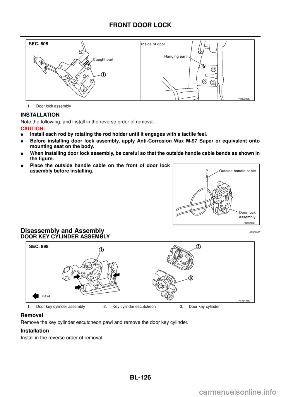
INSTALLATION
Note the following, and install in the reverse order of removal.
CAUTION:
�Install each rod by rotating the rod holder until it engages with a tactile feel.
�Before installing door lock assembly, apply Anti-Corrosion Wax M-97 Super or equivalent onto
mounting seat on the body.
�When installing door lock assembly, be careful so that the outside handle cable bends as shown in
the figure.
�Place the outside handle cable on the front of door lock
assembly before installing.
Disassembly and AssemblyBIS000XX
DOOR KEY CYLINDER ASSEMBLY
Removal
Remove the key cylinder escutcheon pawl and remove the door key cylinder.
Installation
Install in the reverse order of removal.
1. Door lock assembly
PIIB0296E
PIIB0284E
1. Door key cylinder assembly 2. Key cylinder escutcheon 3. Door key cylinder
PIIA6431E
Page 785 of 3502
FRONT DOOR LOCK
BL-127
C
D
E
F
G
H
J
K
L
MA
B
BL
OUTSIDE HANDLE
Removal
1. Remove handle cover screws.
2. Remove handle cover, and then remove door antenna. (Vehicles with intelligent key systems only)
Installation
Install in the reverse order of removal.
1. Outside handle 2. Screw 3. Handle cover
4. Door request switch 5. Pawl 6. Door antenna
PIIB0285E

. (D")
 of the outside handle bracket.
12. While pulling outside handle bracket, slide toward front of vehi-
cle to remove out")