Page 191 of 3502

TROUBLE DIAGNOSIS FOR SYMPTOMS
AT-183
D
E
F
G
H
I
J
K
L
MA
B
AT
4. CHECK LINE PRESSURE
Check line pressure at stall point with selector lever in “D” position. Refer to AT- 4 6 , "
LINE PRESSURE TEST" .
OK or NG
OK >> GO TO 6.
NG >> GO TO 5.
5. DETECT MALFUNCTIONING ITEM
1. Remove control valve assembly. Refer to AT- 2 2 5 , "
Control Valve Assembly and Accumulators" .
2. Check the following items:
–Shift valve A
–Shift valve B
–Shift solenoid valve A
–Shift solenoid valve B
–Pilot valve
–Pilot filter
3. Disassemble A/T. Refer to AT- 2 5 5 , "
Disassembly" .
4. Check the following items:
–Forward clutch assembly. Refer to AT- 3 0 7 , "Forward and Overrun Clutches" .
–Low one-way clutch. Refer to AT- 2 5 5 , "Disassembly" .
–Forward one-way clutch. Refer to AT- 3 1 9 , "Rear Internal Gear, Forward Clutch Hub and Overrun Clutch
Hub" .
–High clutch assembly. Refer to AT- 3 0 1 , "High Clutch" .
–Torque converter. Refer to AT-255, "Disassembly" .
–Oil pump assembly. Refer to AT- 2 7 5 , "Oil Pump" .
OK or NG
OK >> GO TO 8.
NG >> Repair or replace damaged parts.
6. CHECK A/T FLUID CONDITION
1. Remove oil pan. Refer to AT- 2 4 6 , "
Components" .
2. Check A/T fluid condition. Refer to AT- 4 3 , "
A/T Fluid Condition Check" .
OK or NG
OK >> GO TO 7.
NG >> GO TO 5.
7. DETECT MALFUNCTIONING ITEM
1. Remove control valve assembly. Refer to AT- 2 2 5 , "
Control Valve Assembly and Accumulators" .
2. Check the following items:
–Shift valve A
–Shift valve B
–Shift solenoid valve A
–Shift solenoid valve B
–Pilot valve
–Pilot filter
OK or NG
OK >> GO TO 8.
NG >> Repair or replace damage parts.
Page 193 of 3502

TROUBLE DIAGNOSIS FOR SYMPTOMS
AT-185
D
E
F
G
H
I
J
K
L
MA
B
AT
5. CHECK A/T FLUID CONDITION
1. Remove oil pan. Refer to AT- 2 4 6 , "
Components" .
2. Check A/T fluid condition. Refer to AT- 4 3 , "
A/T Fluid Condition Check" .
OK or NG
OK >> GO TO 7.
NG >> GO TO 6.
6. DETECT MALFUNCTIONING ITEM
1. Remove control valve. Refer to AT- 2 2 5 , "
Control Valve Assembly and Accumulators" .
2. Check the following items:
–Shift valve A
–Shift valve B
–Shift solenoid valve A
–Shift solenoid valve B
–Pilot valve
–Pilot filter
3. Disassemble A/T. Refer to AT- 2 5 5 , "
Disassembly" .
4. Check the following items:
–Servo piston assembly
–Brake band
OK or NG
OK >> GO TO 8.
NG >> Repair or replace damaged parts.
7. DETECT MALFUNCTIONING ITEM
1. Remove control valve. Refer to AT- 2 2 5 , "
Control Valve Assembly and Accumulators" .
2. Check the following items:
–Shift valve A
–Shift valve B
–Shift solenoid valve A
–Shift solenoid valve B
–Pilot valve
–Pilot filter
OK or NG
OK >> GO TO 8.
NG >> Repair or replace damaged parts.
8. SYMPTOM CHECK
Check again. Refer to AT- 5 0 , "
Cruise Test — Part 1" and AT- 5 1 , "Cruise Test — Part 2" .
OK or NG
OK >>INSPECTION END
NG >> GO TO 9.
9. CHECK TCM
1. Check TCM input/output signals. Refer to AT- 6 4 , "
TCM Terminals and Reference Value" .
2. If NG, recheck TCM pin terminals for damage or loose connection with harness connector.
OK or NG
OK >>INSPECTION END
NG >> Repair or replace damaged parts.
Page 195 of 3502

TROUBLE DIAGNOSIS FOR SYMPTOMS
AT-187
D
E
F
G
H
I
J
K
L
MA
B
AT
6. DETECT MALFUNCTIONING ITEM
1. Remove control valve assembly. Refer to AT- 2 2 5 , "
Control Valve Assembly and Accumulators" .
2. Check the following items:
–Shift valve B
–Shift solenoid valve B
–Pilot valve
–Pilot filter
3. Disassemble A/T. Refer to AT- 2 5 5 , "
Disassembly" .
4. Check the following items:
–Servo piston assembly
–High clutch assembly. Refer to AT- 3 0 1 , "High Clutch" .
–Oil pump assembly. Refer to AT- 2 7 5 , "Oil Pump" .
OK or NG
OK >> GO TO 8.
NG >> Repair or replace damaged parts.
7. DETECT MALFUNCTIONING ITEM
1. Remove control valve assembly. Refer to AT- 2 2 5 , "
Control Valve Assembly and Accumulators" .
2. Check the following items:
–Shift valve B
–Shift solenoid valve B
–Pilot valve
–Pilot filter
OK or NG
OK >> GO TO 8.
NG >> Repair or replace damaged parts.
8. SYMPTOM CHECK
Check again. Refer to AT- 5 0 , "
Cruise Test — Part 1" and AT- 5 1 , "Cruise Test — Part 2" .
OK or NG
OK >>INSPECTION END
NG >> GO TO 9.
9. CHECK TCM
1. Check TCM input/output signal. Refer to AT- 6 4 , "
TCM Terminals and Reference Value" .
2. If NG, recheck TCM pin terminals for damage or loose connection with harness connector.
OK or NG
OK >>INSPECTION END
NG >> Repair or replace damaged parts.
Page 198 of 3502
 or EC-
652, \"DTC P2138")
AT-190
TROUBLE DIAGNOSIS FOR SYMPTOMS
5. CHECK ACCELERATOR PEDAL POSITION SENSOR
Check accelerator pedal position sensor. Refer to EC-272, "
DTC P2138 APP SENSOR" (QR engine) or EC-
652, "DTC P2138 APP SENSOR" (VQ engine).
OK or NG
OK >> GO TO 6.
NG >> Repair or replace accelerator pedal position sensor.
6. CHECK A/T FLUID CONDITION
1. Remove oil pan. Refer to AT- 2 4 6 , "
Components" .
2. Check A/T fluid condition. Refer to AT- 4 3 , "
A/T Fluid Condition Check" .
OK or NG
OK >> GO TO 8.
NG >> GO TO 7.
7. DETECT MALFUNCTIONING ITEM
1. Remove control valve assembly. Refer to AT- 2 2 5 , "
Control Valve Assembly and Accumulators" .
2. Check the following items:
–Shift valve A
–Overrun clutch control valve
–Shift solenoid valve A
–Overrun clutch solenoid valve
–Pilot valve
–Pilot filter
3. Disassemble A/T. Refer to AT- 2 5 5 , "
Disassembly" .
4. Check the following items:
–Servo piston assembly
–Brake band
–Torque converter. Refer to AT- 2 5 5 , "Disassembly" .
–Oil pump assembly. Refer to AT- 2 7 5 , "Oil Pump" .
OK or NG
OK >> GO TO 9.
NG >> Repair or replace damaged parts.
8. DETECT MALFUNCTIONING ITEM
1. Remove control valve assembly. Refer to AT- 2 2 5 , "
Control Valve Assembly and Accumulators" .
2. Check the following items:
–Shift valve A
–Overrun clutch control valve
– Shift solenoid valve A
–Pilot valve
–Pilot filter
OK or NG
OK >> GO TO 9.
NG >> Repair or replace damaged parts.
Page 201 of 3502

TROUBLE DIAGNOSIS FOR SYMPTOMS
AT-193
D
E
F
G
H
I
J
K
L
MA
B
AT
4. DETECT MALFUNCTIONING ITEM
1. Remove control valve assembly. Refer to AT- 2 2 5 , "
Control Valve Assembly and Accumulators" .
2. Check following items:
–Torque converter clutch control valve
–Torque converter clutch solenoid valve
–Torque converter relief valve
–Pilot valve
–Pilot filter
3. Remove A/T. Refer to AT- 2 5 5 , "
Disassembly" .
4. Check the following items:
–Torque converter. Refer to AT-255, "Disassembly" .
OK or NG
OK >> GO TO 5.
NG >> Repair or replace damaged parts.
5. SYMPTOM CHECK
Check again. Refer to AT- 5 0 , "
Cruise Test — Part 1" .
OK or NG
OK >>INSPECTION END
NG >> GO TO 6.
6. CHECK TCM
1. Check TCM input/output signals. Refer to AT- 6 4 , "
TCM Terminals and Reference Value" .
2. If NG, recheck TCM pin terminals for damage or loose connection with harness connector.
OK or NG
OK >>INSPECTION END
NG >> Repair or replace damaged parts.
A/T Does Not Hold Lock-up ConditionBCS0014L
SYMPTOM:
A/T does not hold lock-up condition for more than 30 seconds on “Cruise Test — Part 1”.
DIAGNOSTIC PROCEDURE
1. CHECK SELF-DIAGNOSTIC RESULTS
Perform self-diagnosis. Refer to AT- 6 9 , "
SELF-DIAGNOSTIC RESULT MODE" or AT- 7 6 , "Diagnostic Proce-
dure Without CONSULT-II" .
Is any malfunction detected by self-diagnostic results?
YES >> Check the malfunctioning systems. Refer to AT- 6 9 , "SELF-DIAGNOSTIC RESULT MODE" or AT-
77, "Judgement of Self-Diagnosis Code" .
NO >> GO TO 2.
2. CHECK A/T FLUID CONDITION
1. Remove oil pan. Refer to AT- 2 4 6 , "
Components" .
2. Check A/T fluid condition. Refer to AT- 4 3 , "
A/T Fluid Condition Check" .
OK or NG
OK >> GO TO 4.
NG >> GO TO 3.
Page 202 of 3502

AT-194
TROUBLE DIAGNOSIS FOR SYMPTOMS
3. DETECT MALFUNCTIONING ITEM
1. Remove control valve assembly. Refer to AT- 2 2 5 , "
Control Valve Assembly and Accumulators" .
2. Check the following items:
–Torque converter clutch control valve
–Torque converter clutch solenoid valve
–Pilot valve
–Pilot filter
3. Disassemble A/T. Refer to AT- 2 5 5 , "
Disassembly" .
4. Check the following items:
–Torque converter. Refer to AT- 2 5 5 , "Disassembly" .
–Oil pump assembly. Refer to AT- 2 7 5 , "Oil Pump" .
OK or NG
OK >> GO TO 5.
NG >> Repair or replace damaged parts.
4. DETECT MALFUNCTIONING ITEM
1. Remove control valve assembly. Refer to AT- 2 2 5 , "
Control Valve Assembly and Accumulators" .
2. Check the following items:
–Torque converter clutch control valve
–Torque converter clutch solenoid valve
–Pilot valve
–Pilot filter
OK or NG
OK >> GO TO 5.
NG >> Repair or replace damaged parts.
5. SYMPTOM CHECK
Check again. Refer to AT- 5 0 , "
Cruise Test — Part 1" .
OK or NG
OK >>INSPECTION END
NG >> GO TO 6.
6. CHECK TCM
1. Check TCM input/output signals. Refer to AT- 6 4 , "
TCM Terminals and Reference Value" .
2. If NG, recheck TCM pin terminals for damage or loose connection with harness connector.
OK or NG
OK >>INSPECTION END
NG >> Repair or replace damaged parts.
Page 288 of 3502
AT-280
REPAIR FOR COMPONENT PARTS
Control Valve AssemblyBCS001OL
COMPONENTS
1. Oil strainer 2. O-ring 3. Snap ring
4. Terminal body 5. O-ring 6. Solenoid valve assembly
7. Control valve lower body 8. Oil cooler relief valve spring 9. Check ball
10. Separating plate 11. Support plate 12. Steel ball
13. Control valve inter body 14. Pilot filter 15. Separating plate
16. Steel ball 17. Control valve upper body
SCIA4973E
Page 293 of 3502
REPAIR FOR COMPONENT PARTS
AT-285
D
E
F
G
H
I
J
K
L
MA
B
AT
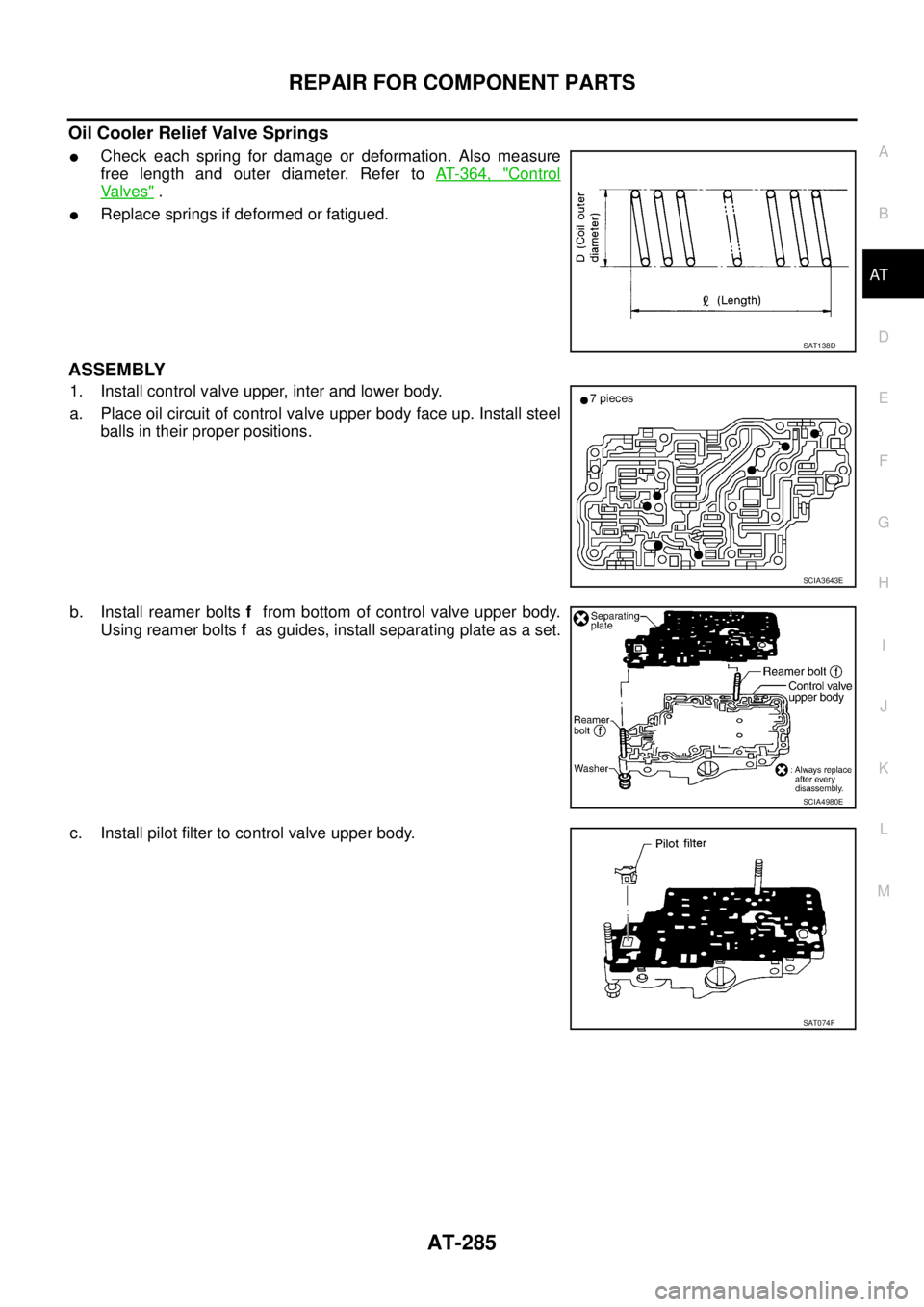
Oil Cooler Relief Valve Springs
�Check each spring for damage or deformation. Also measure
free length and outer diameter. Refer to AT- 3 6 4 , "
Control
Va l v e s" .
�Replace springs if deformed or fatigued.
ASSEMBLY
1. Install control valve upper, inter and lower body.
a. Place oil circuit of control valve upper body face up. Install steel
balls in their proper positions.
b. Install reamer bolts f from bottom of control valve upper body.
Using reamer bolts f as guides, install separating plate as a set.
c. Install pilot filter to control valve upper body.
SAT138D
SCIA3643E
SCIA4980E
SAT074F