2003 NISSAN ALMERA N16 P0171
[x] Cancel search: P0171Page 332 of 3189
EC-2
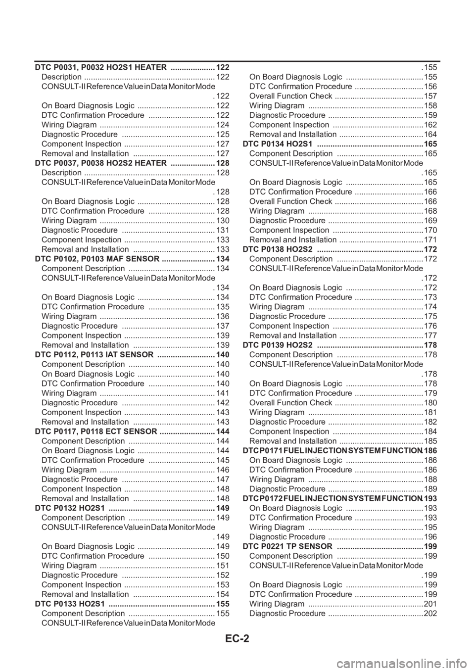
DTC P0031, P0032 HO2S1 HEATER .....................122
Description ............................................................122
CONSULT-II Reference Value in Data Monitor Mode
.122
On Board Diagnosis Logic ....................................122
DTC Confirmation Procedure ...............................122
Wiring Diagram .....................................................124
Diagnostic Procedure ...........................................125
Component Inspection ..........................................127
Removal and Installation ......................................127
DTC P0037, P0038 HO2S2 HEATER .....................128
Description ............................................................128
CONSULT-II Reference Value in Data Monitor Mode
.128
On Board Diagnosis Logic ....................................128
DTC Confirmation Procedure ...............................128
Wiring Diagram .....................................................130
Diagnostic Procedure ...........................................131
Component Inspection ..........................................133
Removal and Installation ......................................133
DTC P0102, P0103 MAF SENSOR .........................134
Component Description ........................................134
CONSULT-II Reference Value in Data Monitor Mode
.134
On Board Diagnosis Logic ....................................134
DTC Confirmation Procedure ...............................135
Wiring Diagram .....................................................136
Diagnostic Procedure ...........................................137
Component Inspection ..........................................139
Removal and Installation ......................................139
DTC P0112, P0113 IAT SENSOR ...........................140
Component Description ........................................140
On Board Diagnosis Logic ....................................140
DTC Confirmation Procedure ...............................140
Wiring Diagram .....................................................141
Diagnostic Procedure ...........................................142
Component Inspection ..........................................143
Removal and Installation ......................................143
DTC P0117, P0118 ECT SENSOR ..........................144
Component Description ........................................144
On Board Diagnosis Logic ....................................144
DTC Confirmation Procedure ...............................145
Wiring Diagram .....................................................146
Diagnostic Procedure ...........................................147
Component Inspection ..........................................148
Removal and Installation ......................................148
DTC P0132 HO2S1 .................................................149
Component Description ........................................149
CONSULT-II Reference Value in Data Monitor Mode
.149
On Board Diagnosis Logic ...................................
.149
DTC Confirmation Procedure ...............................150
Wiring Diagram .....................................................151
Diagnostic Procedure ...........................................152
Component Inspection ..........................................153
Removal and Installation ......................................154
DTC P0133 HO2S1 .................................................155
Component Description ........................................155
CONSULT-II Reference Value in Data Monitor Mode .155
On Board Diagnosis Logic ....................................155
DTC Confirmation Procedure ................................156
Overall Function Check .........................................157
Wiring Diagram .....................................................158
Diagnostic Procedure ............................................159
Component Inspection ..........................................162
Removal and Installation .......................................164
DTC P0134 HO2S1 ................................................ .165
Component Description ........................................165
CONSULT-II Reference Value in Data Monitor Mode
.165
On Board Diagnosis Logic ....................................165
DTC Confirmation Procedure ................................166
Overall Function Check .........................................166
Wiring Diagram .....................................................168
Diagnostic Procedure ............................................169
Component Inspection ..........................................170
Removal and Installation .......................................171
DTC P0138 HO2S2 ................................................ .172
Component Description ........................................172
CONSULT-II Reference Value in Data Monitor Mode
.172
On Board Diagnosis Logic ....................................172
DTC Confirmation Procedure ................................173
Wiring Diagram .....................................................174
Diagnostic Procedure ............................................175
Component Inspection ..........................................176
Removal and Installation .......................................177
DTC P0139 HO2S2 ................................................ .178
Component Description ........................................178
CONSULT-II Reference Value in Data Monitor Mode
.178
On Board Diagnosis Logic ....................................178
DTC Confirmation Procedure ................................179
Overall Function Check .........................................180
Wiring Diagram .....................................................181
Diagnostic Procedure ............................................182
Component Inspection ..........................................184
Removal and Installation ......................................
.185
DTC P0171 FUEL INJECTION SYSTEM FUNCTION .186
On Board Diagnosis Logic ....................................186
DTC Confirmation Procedure ................................186
Wiring Diagram .....................................................188
Diagnostic Procedure ............................................189
DTC P0172 FUEL INJECTION SYSTEM FUNCTION .193
On Board Diagnosis Logic ....................................193
DTC Confirmation Procedure ................................193
Wiring Diagram .....................................................195
Diagnostic Procedure ............................................196
DTC P0221 TP SENSOR ........................................199
Component Description ........................................199
CONSULT-II Reference Value in Data Monitor Mode
.199
On Board Diagnosis Logic ....................................199
DTC Confirmation Procedure ................................199
Wiring Diagram .....................................................201
Diagnostic Procedure ............................................202
Page 340 of 3189
![NISSAN ALMERA N16 2003 Electronic Repair Manual EC-10
[QG (WITH EURO-OBD)]
INDEX FOR DTC
[QG (WITH EURO-OBD)]INDEX FOR DTCPFP:00024
Alphabetical IndexEBS00K2T
Check if the vehicle is a model with Euro-OBD (E-OBD) system or not by the “Type approv](/manual-img/5/57350/w960_57350-339.png "NISSAN ALMERA N16 2003 Electronic Repair Manual EC-10
[QG (WITH EURO-OBD)]
INDEX FOR DTC
[QG (WITH EURO-OBD)]INDEX FOR DTCPFP:00024
Alphabetical IndexEBS00K2T
Check if the vehicle is a model with Euro-OBD (E-OBD) system or not by the “Type approv")
EC-10
[QG (WITH EURO-OBD)]
INDEX FOR DTC
[QG (WITH EURO-OBD)]INDEX FOR DTCPFP:00024
Alphabetical IndexEBS00K2T
Check if the vehicle is a model with Euro-OBD (E-OBD) system or not by the “Type approval number” on the
identification plate. Refer to GI-39.
NOTE:
If DTC U1000 or U1001 is displayed with other DTC, first perform the trouble diagnosis for DTC U1000,
U1001. Refer to EC-116, "
DTC U1000, U1001 CAN COMMUNICATION LINE" .
×: Applicable –: Not applicable
Items
(CONSULT-II screen terms)DTC*
1
TripMI lighting
upReference page
CONSULT-II
GST*
2ECM*3
A/T 1ST GR FNCTN P0731 0731 2×AT-133
A/T 2ND GR FNCTN P0732 0732 2×AT-139
A/T 3RD GR FNCTN P0733 0733 2×AT-145
A/T 4TH GR FNCTN P0734 0734 2×AT-151
APP SEN 1/CIRC P0227 0227 1×EC-218
APP SEN 1/CIRC P0228 0228 1×EC-218
APP SEN 2/CIRC P1227 1227 1×EC-345
APP SEN 2/CIRC P1228 1228 1×EC-345
APP SENSOR P0226 0226 1×EC-211
ATF TEMP SEN/CIRC P0710 0710 2×AT- 11 7
BRAKE SW/CIRCUIT P1805 1805 2 –EC-360
CAN COMM CIRCUIT U1000
1000*51×EC-116
CAN COMM CIRCUIT U1001
1001*52–EC-116
CKP SEN/CIRCUIT P0335 0335 2×EC-234
CMP SEN/CIRC-B1 P0340 0340 2×EC-240
CTP LEARNING P1225 1225 2 –EC-341
CTP LEARNING P1226 1226 2 –EC-343
CYL 1 MISFIRE P0301 0301 2×EC-225
CYL 2 MISFIRE P0302 0302 2×EC-225
CYL 3 MISFIRE P0303 0303 2×EC-225
CYL 4 MISFIRE P0304 0304 2×EC-225
ECM P0605 0605 1 or 2× or –EC-265
ECM BACK UP/CIRC P1065 1065 2×EC-268
ECT SEN/CIRCUIT P0117 0117 1×EC-144
ECT SEN/CIRCUIT P0118 0118 1×EC-144
ENG OVER TEMP P1217 1217 1×EC-324
ENGINE SPEED SIG P0725 0725 1×AT-129
ETC ACTR P1121 1121 1 or 2×EC-276
ETC FUNCTION/CIRC P1122 1122 1×EC-278
ETC MOT P1128 1128 1×EC-291
ETC MOT PWR P1124 1124 1×EC-285
ETC MOT PWR P1126 1126 1×EC-285
FUEL SYS-LEAN-B1 P0171 0171 2×EC-186
FUEL SYS-RICH-B1 P0172 0172 2×EC-193
HO2S1 (B1) P0132 0132 2×EC-149
Page 342 of 3189
![NISSAN ALMERA N16 2003 Electronic Repair Manual EC-12
[QG (WITH EURO-OBD)]
INDEX FOR DTC
*1: 1st trip DTC No. is the same as DTC No.
*2: These numbers are prescribed by ISO 15031-5.
*3: In Diagnostic Test Mode II (Self-diagnostic results), these nu](/manual-img/5/57350/w960_57350-341.png "NISSAN ALMERA N16 2003 Electronic Repair Manual EC-12
[QG (WITH EURO-OBD)]
INDEX FOR DTC
*1: 1st trip DTC No. is the same as DTC No.
*2: These numbers are prescribed by ISO 15031-5.
*3: In Diagnostic Test Mode II (Self-diagnostic results), these nu")
EC-12
[QG (WITH EURO-OBD)]
INDEX FOR DTC
*1: 1st trip DTC No. is the same as DTC No.
*2: These numbers are prescribed by ISO 15031-5.
*3: In Diagnostic Test Mode II (Self-diagnostic results), these numbers are controlled by NISSAN.
*4: When engine is running.
*5: The troubleshooting for this DTC needs CONSULT-II.
*6: When the fail-safe operations for both self-diagnoses occur, the MI illuminates.
DTC No. IndexEBS00K2U
Check if the vehicle is a model with Euro-OBD (E-OBD) system or not by the “Type approval number” on the
identification plate. Refer to GI-39.
NOTE:
If DTC U1000 or U1001 is displayed with other DTC, first perform the trouble diagnosis for DTC U1000,
U1001. Refer to EC-116, "
DTC U1000, U1001 CAN COMMUNICATION LINE" .
×: Applicable –: Not applicable TW CATALYST SYS-B1 P0420 0420 2×EC-246
VEH SPD SEN/CIR AT*6P0720 0720 2×AT-123
VEH SPEED SEN/CIRC P0500 0500 2×EC-257
Items
(CONSULT-II screen terms)DTC*
1
TripMI lighting
upReference page
CONSULT-II
GST*
2ECM*3
DTC*1
Items
(CONSULT-II screen terms)TripMI lighting
upReference page
CONSULT-II
GST*
2ECM*3
No DTC
Flashing*4NO DTC IS DETECTED.
FURTHER TESTING
MAY BE REQUIRED.–
Flashing*4EC-50
U1000
1000*5CAN COMM CIRCUIT 1×EC-116
U1001
1001*5CAN COMM CIRCUIT 2 –EC-116
P0000 0000NO DTC IS DETECTED.
FURTHER TESTING
MAY BE REQUIRED.––—
P0011 0011 INT/V TIM CONT-B1 2 –EC-119
P0031 0031 HO2S1 HTR (B1) 2×EC-122
P0032 0032 HO2S1 HTR (B1) 2×EC-122
P0037 0037 HO2S2 HTR (B1) 2×EC-128
P0038 0038 HO2S2 HTR (B1) 2×EC-128
P0102 0102 MAF SEN/CIRCUIT 1×EC-134
P0103 0103 MAF SEN/CIRCUIT 1×EC-134
P0112 0112 IAT SEN/CIRCUIT 2×EC-140
P0113 0113 IAT SEN/CIRCUIT 2×EC-140
P0117 0117 ECT SEN/CIRCUIT 1×EC-144
P0118 0118 ECT SEN/CIRCUIT 1×EC-144
P0132 0132 HO2S1 (B1) 2×EC-149
P0133 0133 HO2S1 (B1) 2×EC-155
P0134 0134 HO2S1 (B1) 2×EC-165
P0138 0138 HO2S2 (B1) 2×EC-172
P0139 0139 HO2S2 (B1) 2×EC-178
P0171 0171 FUEL SYS-LEAN-B1 2×EC-186
P0172 0172 FUEL SYS-RICH-B1 2×EC-193
P0221 0221 TP SENSOR 1×EC-199
Page 367 of 3189
![NISSAN ALMERA N16 2003 Electronic Repair Manual ON BOARD DIAGNOSTIC (OBD) SYSTEM
EC-37
[QG (WITH EURO-OBD)]
C
D
E
F
G
H
I
J
K
L
MA
EC
The fail-safe function also operates when above diagnoses except MI circuit and demands the driver to repair
the m](/manual-img/5/57350/w960_57350-366.png "NISSAN ALMERA N16 2003 Electronic Repair Manual ON BOARD DIAGNOSTIC (OBD) SYSTEM
EC-37
[QG (WITH EURO-OBD)]
C
D
E
F
G
H
I
J
K
L
MA
EC
The fail-safe function also operates when above diagnoses except MI circuit and demands the driver to repair
the m")
ON BOARD DIAGNOSTIC (OBD) SYSTEM
EC-37
[QG (WITH EURO-OBD)]
C
D
E
F
G
H
I
J
K
L
MA
EC
The fail-safe function also operates when above diagnoses except MI circuit and demands the driver to repair
the malfunction.
Emission-related Diagnostic InformationEBS00K3H
EMISSION-RELATED DIAGNOSTIC INFORMATION ITEMS
Engine operating condition in fail-safe mode Engine speed will not rise more than 2,500 rpm due to the fuel cut
Items
(CONSULT-II screen terms)DTC*
1
SRT codeTest Value/
Test Limit
(GST only)1st trip DTC Reference page
CONSULT-II
GST*
2ECM
CAN COMM CIRCUIT U1000
1000*
3———EC-116
CAN COMM CIRCUIT U1001
1001*3——×EC-116
NO DTC IS DETECTED.
FURTHER TESTING
MAY BE REQUIRED.P0000 0000————
INT/V TIM CONT-B1 P0011 0011 — —×EC-119
HO2S1 HTR (B1) P0031 0031××
×*4EC-122
HO2S1 HTR (B1) P0032 0032××
×*4EC-122
HO2S2 HTR (B1) P0037 0037××
×*4EC-128
HO2S2 HTR (B1) P0038 0038××
×*4EC-128
MAF SEN/CIRCUIT P0102 0102 — — —EC-134
MAF SEN/CIRCUIT P0103 0103 — — —EC-134
IAT SEN/CIRCUIT P0112 0112 — —×EC-140
IAT SEN/CIRCUIT P0113 0113 — —×EC-140
ECT SEN/CIRCUIT P0117 0117 — — —EC-144
ECT SEN/CIRCUIT P0118 0118 — — —EC-144
HO2S1 (B1) P0132 0132××
×*4EC-149
HO2S1 (B1) P0133 0133××
×*4EC-155
HO2S1 (B1) P0134 0134××
×*4EC-165
HO2S2 (B1) P0138 0138××
×*4EC-172
HO2S2 (B1) P0139 0139××
×*4EC-178
FUEL SYS-LEAN-B1 P0171 0171 — —×EC-186
FUEL SYS-RICH-B1 P0172 0172 — —×EC-193
TP SENSOR P0221 0221 — — —EC-199
TP SEN 1/CIRC P0222 0222 — — —EC-205
TP SEN 1/CIRC P0223 0223 — — —EC-205
APP SENSOR P0226 0226 — — —EC-211
APP SEN 1/CIRC P0227 0227 — — —EC-218
APP SEN 1/CIRC P0228 0228 — — —EC-218
MULTI CYL MISFIRE P0300 0300 — —×EC-225
CYL 1 MISFIRE P0301 0301 — —×EC-225
CYL 2 MISFIRE P0302 0302 — —×EC-225
CYL 3 MISFIRE P0303 0303 — —×EC-225
CYL 4 MISFIRE P0304 0304 — —×EC-225
KNOCK SEN/CIRC-B1 P0327 0327 — —×EC-230
KNOCK SEN/CIRC-B1 P0328 0328 — —×EC-230
CKP SEN/CIRCUIT P0335 0335 — —×EC-234
Page 370 of 3189
![NISSAN ALMERA N16 2003 Electronic Repair Manual EC-40
[QG (WITH EURO-OBD)]
ON BOARD DIAGNOSTIC (OBD) SYSTEM
If a 1st trip DTC is stored in the ECM, the time data will be “[1t]”.
FREEZE FRAME DATA AND 1ST TRIP FREEZE FRAME DATA
The ECM records t](/manual-img/5/57350/w960_57350-369.png "NISSAN ALMERA N16 2003 Electronic Repair Manual EC-40
[QG (WITH EURO-OBD)]
ON BOARD DIAGNOSTIC (OBD) SYSTEM
If a 1st trip DTC is stored in the ECM, the time data will be “[1t]”.
FREEZE FRAME DATA AND 1ST TRIP FREEZE FRAME DATA
The ECM records t")
EC-40
[QG (WITH EURO-OBD)]
ON BOARD DIAGNOSTIC (OBD) SYSTEM
If a 1st trip DTC is stored in the ECM, the time data will be “[1t]”.
FREEZE FRAME DATA AND 1ST TRIP FREEZE FRAME DATA
The ECM records the driving conditions such as fuel system status, calculated load value, engine coolant tem-
perature, short term fuel trim, long term fuel trim, engine speed, vehicle speed, base fuel schedule and intake
air temperature at the moment a malfunction is detected.
Data which are stored in the ECM memory, along with the 1st trip DTC, are called 1st trip freeze frame data.
The data, stored together with the DTC data, are called freeze frame data and displayed on CONSULT-II or
GST. The 1st trip freeze frame data can only be displayed on the CONSULT-II screen, not on the GST. For
details, see EC-90, "
Freeze Frame Data and 1st Trip Freeze Frame Data" .
Only one set of freeze frame data (either 1st trip freeze frame data or freeze frame data) can be stored in the
ECM. 1st trip freeze frame data is stored in the ECM memory along with the 1st trip DTC. There is no priority
for 1st trip freeze frame data and it is updated each time a different 1st trip DTC is detected. However, once
freeze frame data (2nd trip detection/MI on) is stored in the ECM memory, 1st trip freeze frame data is no
longer stored. Remember, only one set of freeze frame data can be stored in the ECM. The ECM has the fol-
lowing priorities to update the data.
For example, the EGR malfunction (Priority: 2) was detected and the freeze frame data was stored in the 2nd
trip. After that when the misfire (Priority: 1) is detected in another trip, the freeze frame data will be updated
from the EGR malfunction to the misfire. The 1st trip freeze frame data is updated each time a different mal-
function is detected. There is no priority for 1st trip freeze frame data. However, once freeze frame data is
stored in the ECM memory, 1st trip freeze data is no longer stored (because only one freeze frame data or 1st
trip freeze frame data can be stored in the ECM). If freeze frame data is stored in the ECM memory and freeze
frame data with the same priority occurs later, the first (original) freeze frame data remains unchanged in the
ECM memory.
Both 1st trip freeze frame data and freeze frame data (along with the DTCs) are cleared when the ECM mem-
ory is erased. Procedures for clearing the ECM memory are described in EC-48, "
HOW TO ERASE EMIS-
SION-RELATED DIAGNOSTIC INFORMATION" .
SYSTEM READINESS TEST (SRT) CODE
System Readiness Test (SRT) code is specified in Mode 1 of ISO 15031-5.
As part of an enhanced emissions test for Inspection & Maintenance (I/M), certain states require the status of
SRT be used to indicate whether the ECM has completed self-diagnosis of major emission systems and com-
ponents. Completion must be verified in order for the emissions inspection to proceed.
If a vehicle is rejected for a State emissions inspection due to one or more SRT items indicating “INCMP”, use
the information in this Service Manual to set the SRT to “CMPLT”.
In most cases the ECM will automatically complete its self-diagnosis cycle during normal usage, and the SRT
status will indicate “CMPLT” for each application system. Once set as “CMPLT”, the SRT status remains
“CMPLT” until the self-diagnosis memory is erased.
Occasionally, certain portions of the self-diagnostic test may not be completed as a result of the customer's
normal driving pattern; the SRT will indicate “INCMP” for these items.
NOTE:
The SRT will also indicate “INCMP” if the self-diagnosis memory is erased for any reason or if the ECM mem-
ory power supply is interrupted for several hours.
PBIB0911E
Priority Items
1Freeze frame data Misfire — DTC: P0300 - P0304
Fuel Injection System Function — DTC: P0171, P0172
2 Except the above items (Includes A/T related items)
3 1st trip freeze frame data
Page 393 of 3189
![NISSAN ALMERA N16 2003 Electronic Repair Manual TROUBLE DIAGNOSIS
EC-63
[QG (WITH EURO-OBD)]
C
D
E
F
G
H
I
J
K
L
MA
EC
Fail-safe ChartEBS00K3N
●When the DTC listed below is detected, the ECM enters fail-safe mode and the MI lights up.
Priority De](/manual-img/5/57350/w960_57350-392.png "NISSAN ALMERA N16 2003 Electronic Repair Manual TROUBLE DIAGNOSIS
EC-63
[QG (WITH EURO-OBD)]
C
D
E
F
G
H
I
J
K
L
MA
EC
Fail-safe ChartEBS00K3N
●When the DTC listed below is detected, the ECM enters fail-safe mode and the MI lights up.
Priority De")
TROUBLE DIAGNOSIS
EC-63
[QG (WITH EURO-OBD)]
C
D
E
F
G
H
I
J
K
L
MA
EC
Fail-safe ChartEBS00K3N
●When the DTC listed below is detected, the ECM enters fail-safe mode and the MI lights up.
Priority Detected items (DTC)
1
●U1000 U1001 CAN communication line
●P0102 P0103 Mass air flow sensor
●P0112 P0113 Intake air temperature sensor
●P0117 P0118 Engine coolant temperature sensor
●P0221 P0222 P0223 P1223 P1224 P1225 P1226 P1229 Throttle position sensor
●P0226 P0227 P0228 P1227 P1228 Accelerator pedal position sensor
●P0327 P0328 Knock sensor
●P0335 Crankshaft position sensor (POS)
●P0340 Camshaft position sensor (PHASE)
●P0500 Vehicle speed sensor
●P0705 Park/Neutral position (PNP) switch
●P0605 ECM
●P1610-P1615 NATS
●P1706 Park/Neutral position (PNP) switch
2
●P0031 P0032 Heated oxygen sensor 1 heater
●P0037 P0038 Heated oxygen sensor 2 heater
●P0132 P0133 P0134 P1143 P1144 Heated oxygen sensor 1
●P0138 P0139 P1146 P1147 Heated oxygen sensor 2
●P0550 Power steering pressure sensor
●P0710-P0725 P0740-P0755 P1705 P1760 A/T related sensors and solenoid valves
●P1065 ECM power supply
●P 1111 I n ta k e v a l v e t i m i n g c o n t r o l s o l e n o i d v a l v e
●P1122 Electric throttle control function
●P1124 P1126 P1128 Electric throttle control actuator
●P1805 Brake switch
3
●P0011 Intake valve timing control
●P0171 P0172 Fuel injection system function
●P0300 - P0304 Misfire
●P0420 Three way catalyst function
●P0444 EVAP canister purge volume control solenoid valve
●P0731-P0734 A/T function
●P1121 Electric throttle control actuator
●P1217 Engine over temperature (OVERHEAT)
DTC No. Detected items Engine operating condition in fail-safe mode
P0102
P0103Mass air flow sensor circuit Engine speed will not rise more than 2,400 rpm due to the fuel cut.
Page 491 of 3189
![NISSAN ALMERA N16 2003 Electronic Repair Manual DTC P0133 HO2S1
EC-161
[QG (WITH EURO-OBD)]
C
D
E
F
G
H
I
J
K
L
MA
EC
5.CLEAR THE SELF-LEARNING DATA
With CONSULT-II
1. Start engine and warm it up to normal operating temperature.
2. Select “SELF-L](/manual-img/5/57350/w960_57350-490.png "NISSAN ALMERA N16 2003 Electronic Repair Manual DTC P0133 HO2S1
EC-161
[QG (WITH EURO-OBD)]
C
D
E
F
G
H
I
J
K
L
MA
EC
5.CLEAR THE SELF-LEARNING DATA
With CONSULT-II
1. Start engine and warm it up to normal operating temperature.
2. Select “SELF-L")
DTC P0133 HO2S1
EC-161
[QG (WITH EURO-OBD)]
C
D
E
F
G
H
I
J
K
L
MA
EC
5.CLEAR THE SELF-LEARNING DATA
With CONSULT-II
1. Start engine and warm it up to normal operating temperature.
2. Select “SELF-LEARNING CONT” in “WORK SUPPORT” mode with CONSULT-II.
3. Clear the self-learning control coefficient by touching “CLEAR”.
4. Run engine for at least 10 minutes at idle speed.
Is the 1st trip DTC P0171 or P0172 detected?
Is it difficult to start engine?
Without CONSULT-II
1. Start engine and warm it up to normal operating temperature.
2. Turn ignition switch “OFF”.
3. Disconnect mass air flow sensor harness connector, and restart
and run engine for at least 5 seconds at idle speed.
4. Stop engine and reconnect mass air flow sensor harness con-
nector.
5. Make sure that DTC P0102 is displayed.
6. Erase the DTC memory. Refer to EC-48, "
HOW TO ERASE
EMISSION-RELATED DIAGNOSTIC INFORMATION" .
7. Make sure that DTC P0000 is displayed.
8. Run engine for at least 10 minutes at idle speed.
Is the 1st trip DTC P0171 or P0172 detected?
Is it difficult to start engine?
Ye s o r N o
Yes >> Perform trouble diagnosis for DTC P0171 or DTC P0172 (Refer to EC-186 or EC-193 ).
No >> GO TO 6.
6.CHECK HO2S1 GROUND CIRCUIT FOR OPEN AND SHORT
1. Turn ignition switch “OFF”.
2. Disconnect heated oxygen sensor 1 harness connector.
3. Disconnect ECM harness connector.
4. Check harness continuity between ECM terminal 74 and HO2S1
terminal 3. Refer to Wiring Diagram.
5. Also check harness for short to ground and short to power.
OK or NG
OK >> GO TO 7.
NG >> Repair open circuit or short to ground or short to power
in harness or connectors.
SEF215Z
MBIB0096E
Continuity should exist.
MBIB0091E
Page 513 of 3189
![NISSAN ALMERA N16 2003 Electronic Repair Manual DTC P0139 HO2S2
EC-183
[QG (WITH EURO-OBD)]
C
D
E
F
G
H
I
J
K
L
MA
EC
2.CLEAR THE SELF-LEARNING DATA
With CONSULT-II
1. Start engine and warm it up to normal operating temperature.
2. Select “SELF-](/manual-img/5/57350/w960_57350-512.png "NISSAN ALMERA N16 2003 Electronic Repair Manual DTC P0139 HO2S2
EC-183
[QG (WITH EURO-OBD)]
C
D
E
F
G
H
I
J
K
L
MA
EC
2.CLEAR THE SELF-LEARNING DATA
With CONSULT-II
1. Start engine and warm it up to normal operating temperature.
2. Select “SELF-")
DTC P0139 HO2S2
EC-183
[QG (WITH EURO-OBD)]
C
D
E
F
G
H
I
J
K
L
MA
EC
2.CLEAR THE SELF-LEARNING DATA
With CONSULT-II
1. Start engine and warm it up to normal operating temperature.
2. Select “SELF-LEARNING CONT” in “WORK SUPPORT” mode
with CONSULT-II.
3. Clear the self-learning control coefficient by touching “CLEAR”.
4. Run engine for at least 10 minutes at idle speed.
Is the 1st trip DTC P0171 or P0172 detected?
Is it difficult to start engine?
Without CONSULT-II
1. Start engine and warm it up to normal operating temperature.
2. Turn ignition switch “OFF”.
3. Disconnect mass air flow sensor harness connector, and restart
and run engine for at least 5 seconds at idle speed.
4. Stop engine and reconnect mass air flow sensor harness con-
nector.
5. Make sure that DTC P0102 is displayed.
6. Erase the DTC memory. Refer to EC-48, "
HOW TO ERASE
EMISSION-RELATED DIAGNOSTIC INFORMATION" .
7. Make sure that DTC P0000 is displayed.
8. Run engine for at least 10 minutes at idle speed.
Is the 1st trip DTC P0171 or P0172 detected?
Is it difficult to start engine?
Ye s o r N o
Yes >> Perform trouble diagnosis for DTC P0171 or P0172. Refer to EC-186 or EC-193 .
No >> GO TO 3.
3.CHECK HO2S2 GROUND CIRCUIT FOR OPEN AND SHORT
1. Turn ignition switch “OFF”.
2. Disconnect heated oxygen sensor 2 harness connector.
3. Disconnect ECM harness connector.
4. Check harness continuity between ECM terminal 74 and HO2S2
terminal 3.
Refer to Wiring Diagram.
5. Also check harness for short to ground and short to power.
OK or NG
OK >> GO TO 4.
NG >> Repair open circuit or short to ground or short to power
in harness or connectors.
SEF215Z
MBIB0096E
Continuity should exist.
MBIB0256E