2003 NISSAN ALMERA N16 Air conditioner
[x] Cancel search: Air conditionerPage 1071 of 3189
Fuel Injection Control System
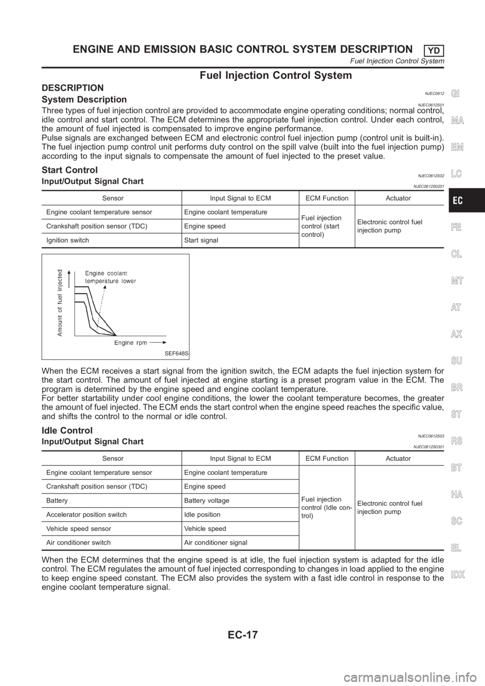
DESCRIPTIONNJEC0612System DescriptionNJEC0612S01Three types of fuel injection control are provided to accommodate engine operating conditions; normal control,
idle control and start control. The ECM determines the appropriate fuel injection control. Under each control,
the amount of fuel injected is compensated to improve engine performance.
Pulse signals are exchanged between ECM and electronic control fuel injection pump (control unit is built-in).
The fuel injection pump control unit performs duty control on the spill valve (built into the fuel injection pump)
according to the input signals to compensate the amount of fuel injected tothe preset value.
Start ControlNJEC0612S02Input/Output Signal ChartNJEC0612S0201
Sensor Input Signal to ECM ECM Function Actuator
Engine coolant temperature sensor Engine coolant temperature
Fuel injection
control (start
control)Electronic control fuel
injection pump Crankshaft position sensor (TDC) Engine speed
Ignition switch Start signal
SEF648S
When the ECM receives a start signal from the ignition switch, the ECM adapts the fuel injection system for
the start control. The amount of fuel injected at engine starting is a preset program value in the ECM. The
program is determined by the engine speed and engine coolant temperature.
For better startability under cool engine conditions, the lower the coolant temperature becomes, the greater
the amount of fuel injected. The ECM ends the start control when the engine speed reaches the specific value,
and shifts the control to the normal or idle control.
Idle ControlNJEC0612S03Input/Output Signal ChartNJEC0612S0301
Sensor Input Signal to ECM ECM Function Actuator
Engine coolant temperature sensor Engine coolant temperature
Fuel injection
control (Idle con-
trol)Electronic control fuel
injection pump Crankshaft position sensor (TDC) Engine speed
Battery Battery voltage
Accelerator position switch Idle position
Vehicle speed sensor Vehicle speed
Air conditioner switch Air conditioner signal
When the ECM determines that the engine speed is at idle, the fuel injectionsystem is adapted for the idle
control. The ECM regulates the amount of fuel injected corresponding to changes in load applied to the engine
to keep engine speed constant. The ECM also provides the system with a fast idle control in response to the
engine coolant temperature signal.
GI
MA
EM
LC
FE
CL
MT
AT
AX
SU
BR
ST
RS
BT
HA
SC
EL
IDX
ENGINE AND EMISSION BASIC CONTROL SYSTEM DESCRIPTIONYD
Fuel Injection Control System
EC-17
Page 1073 of 3189
Air Conditioning Cut Control
DESCRIPTIONNJEC0614Input/Output Signal ChartNJEC0614S01
Sensor Input Signal to ECM ECM Function Actuator
Air conditioner switch Air conditioner “ON” signal
Air conditioner
cut controlAir conditioner relay Accelerator position sensor Accelerator valve opening angle
Vehicle speed sensor Vehicle speed
Engine coolant temperature sensor Engine coolant temperature
System DescriptionNJEC0614S02This system improves acceleration when the air conditioner is used.
When the accelerator pedal is fully depressed, the air conditioner is turned off for a few seconds.
When engine coolant temperature becomes excessively high, the air conditioner is turned off. This continues
until the engine coolant temperature returns to normal.
Fuel Cut Control (at no load & high engine
speed)
DESCRIPTIONNJEC0615Input/Output Signal ChartNJEC0615S01
Sensor Input Signal to ECM ECM Function Actuator
Vehicle speed sensor Vehicle speed
Fuel cut controlElectronic control fuel
injection pump Accelerator position switch Accelerator position
Crankshaft position sensor (TDC) Engine speed
If the engine speed is above 2,800 rpm with no load (for example, in neutral and engine speed over 2,800
rpm) fuel will be cut off after some time. The exact time when the fuel is cut off varies based on engine speed.
Fuel cut will operate until the engine speed reaches 1,500 rpm, then fuel cut is cancelled.
NOTE:
This function is different from deceleration control listed under “Fuel Injection Control System”, EC-17.
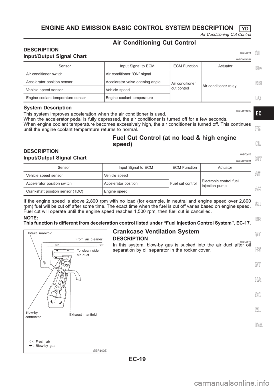
SEF440Z
Crankcase Ventilation System
DESCRIPTIONNJEC0616In this system, blow-by gas is sucked into the air duct after oil
separation by oil separator in the rocker cover.
GI
MA
EM
LC
FE
CL
MT
AT
AX
SU
BR
ST
RS
BT
HA
SC
EL
IDX
ENGINE AND EMISSION BASIC CONTROL SYSTEM DESCRIPTIONYD
Air Conditioning Cut Control
EC-19
Page 1102 of 3189
Basic InspectionNJEC0632Precaution:
Perform Basic Inspection without electrical or mechanical
loads applied;
Headlamp switch is OFF,
On vehicles equipped with daytime light systems, set
lighting switch to the 1st position to light only small
lamps.
Air conditioner switch is OFF,
Rear defogger switch is OFF,
Steering wheel is in the straight-ahead position, etc.
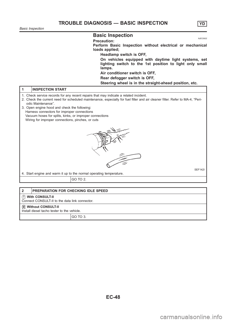
1 INSPECTION START
1. Check service records for any recent repairs that may indicate a relatedincident.
2. Check the current need for scheduled maintenance, especially for fuel filter and air cleaner filter. Refer to MA-4, “Peri-
odic Maintenance”.
3. Open engine hood and check the following:
Harness connectors for improper connections
Vacuum hoses for splits, kinks, or improper connections
Wiring for improper connections, pinches, or cuts
SEF142I
4. Start engine and warm it up to the normal operating temperature.
GO TO 2.
2 PREPARATION FOR CHECKING IDLE SPEED
With CONSULT-II
Connect CONSULT-II to the data link connector.
Without CONSULT-II
Install diesel tacho tester to the vehicle.
GO TO 3.
TROUBLE DIAGNOSIS — BASIC INSPECTIONYD
Basic Inspection
EC-48
Page 1115 of 3189
SYSTEM — ENGINE CONTROL system
Malfunction
SYMPTOM
Reference page
Feature of symptom, Check pointHARD/NO
START/RESTART
(EXCP. HA)
ENGINE STALL
HESITATION/SURGING/FLAT SPOT
KNOCK/DETONATION
LACK OF POWER
POOR ACCELERATION
HI IDLE
LOW IDLE NO START (with first firing)
NO START (without first firing)
HARD TO START WHEN ENGINE IS COLD
HARD TO START WHEN ENGINE IS HOT
AT IDLE
DURING DRIVING
WHEN DECELERATINGWarranty symptom code AA AB AC AD AE AF
ENGINE CONTROL
EGR volume control valve circuit*a, *b
EC-197
*c 1 1 1 *6
Glow relay circuit*a 1111
EC-188*7
*b*8
ECM relay (Self-shutoff) circuit*a 1 111
EC-177
*b*9
ECM, Connector circuit *a, *b 2 2 22222222222EC-175,
11 6
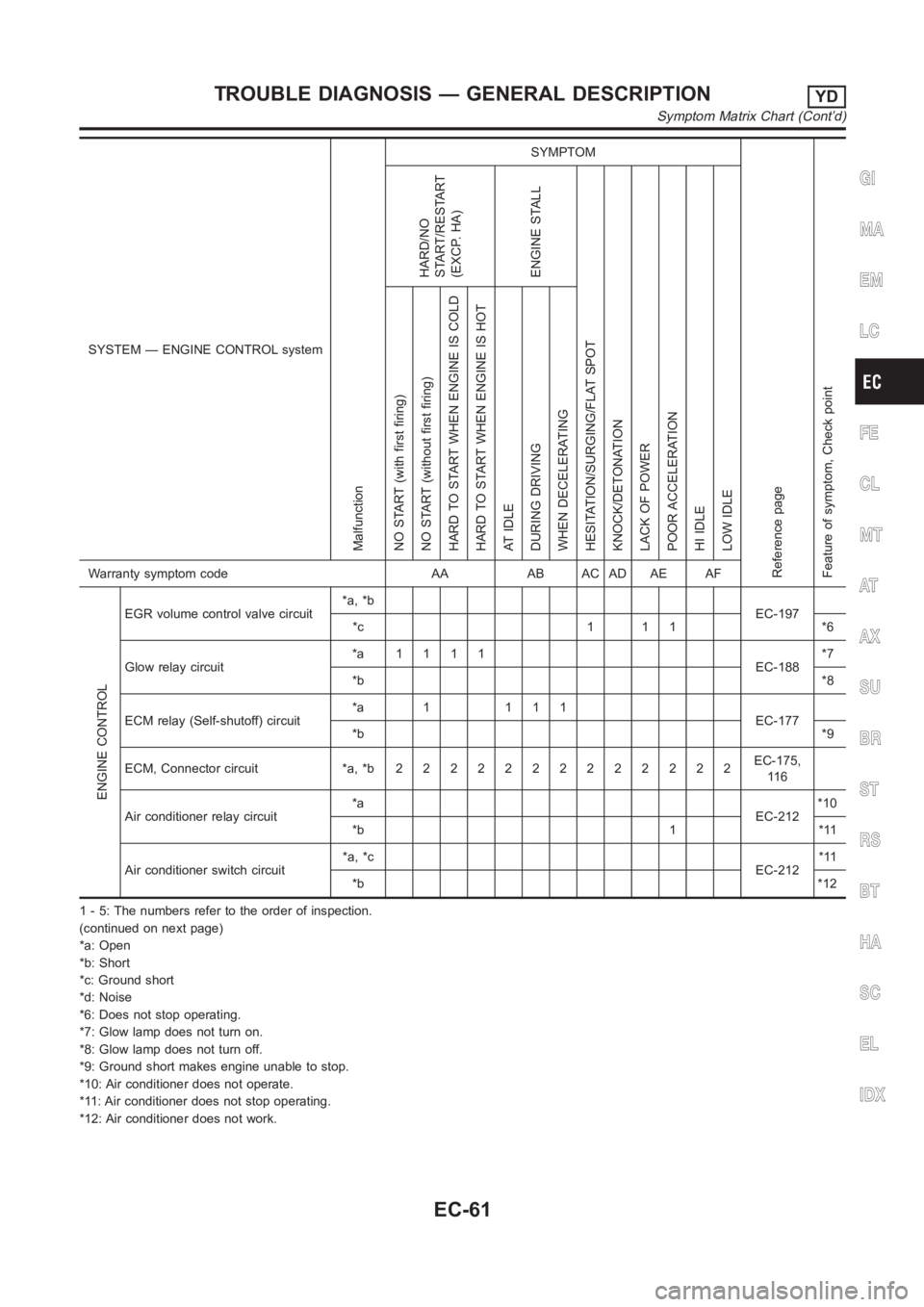
Air conditioner relay circuit*a
EC-212*10
*b 1 *11
Air conditioner switch circuit*a, *c
EC-212*11
*b*12
1 - 5: The numbers refer to the order of inspection.
(continued on next page)
*a: Open
*b: Short
*c: Ground short
*d: Noise
*6: Does not stop operating.
*7: Glow lamp does not turn on.
*8: Glow lamp does not turn off.
*9: Ground short makes engine unable to stop.
*10: Air conditioner does not operate.
*11: Air conditioner does not stop operating.
*12: Air conditioner does not work.
GI
MA
EM
LC
FE
CL
MT
AT
AX
SU
BR
ST
RS
BT
HA
SC
EL
IDX
TROUBLE DIAGNOSIS — GENERAL DESCRIPTIONYD
Symptom Matrix Chart (Cont’d)
EC-61
Page 1116 of 3189
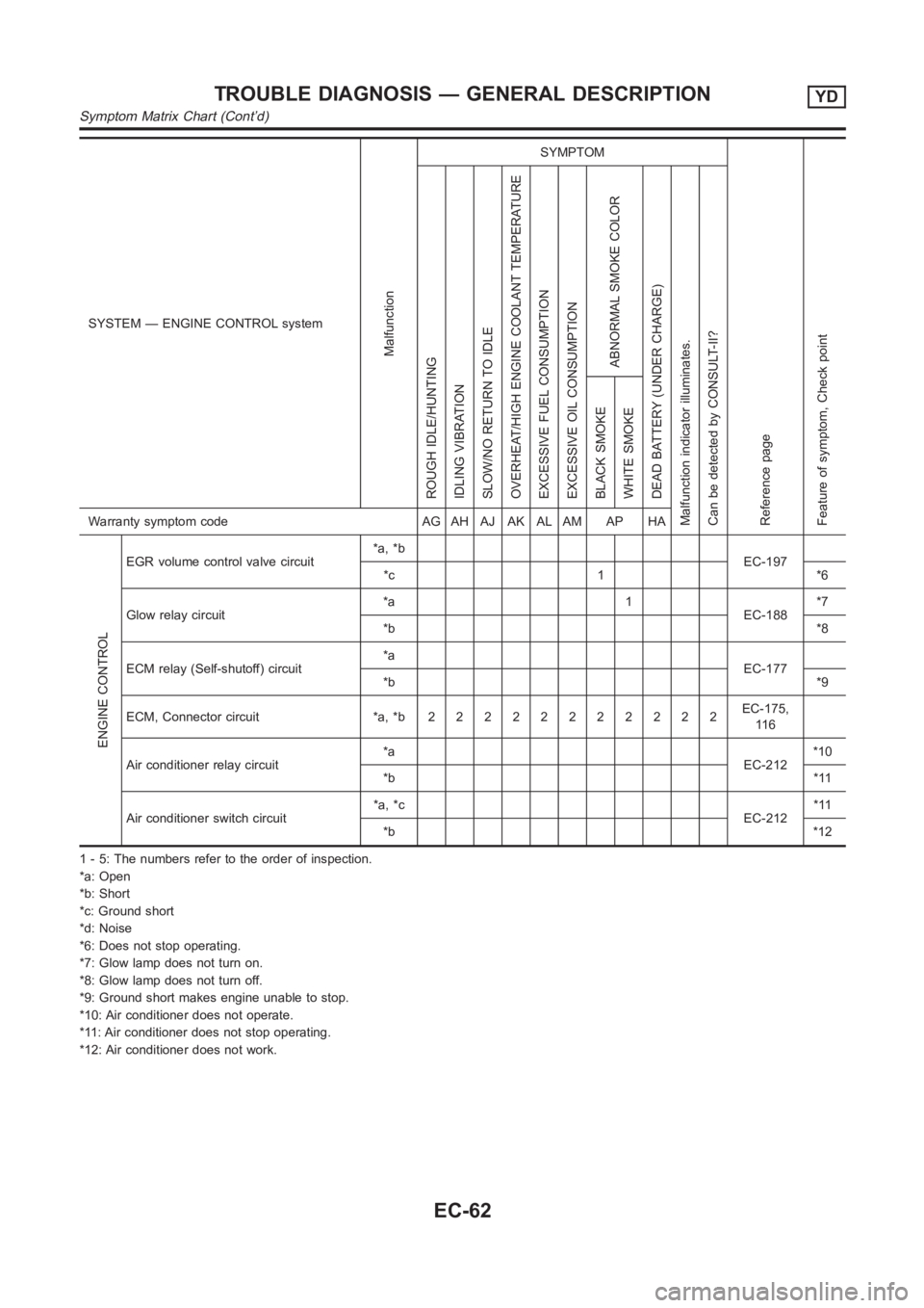
SYSTEM — ENGINE CONTROL system
Malfunction
SYMPTOM
Reference page
Feature of symptom, Check pointROUGH IDLE/HUNTING
IDLING VIBRATION
SLOW/NO RETURN TO IDLE
OVERHEAT/HIGH ENGINE COOLANT TEMPERATURE
EXCESSIVE FUEL CONSUMPTION
EXCESSIVE OIL CONSUMPTION
ABNORMAL SMOKE COLOR
DEAD BATTERY (UNDER CHARGE)
Malfunction indicator illuminates.
Can be detected by CONSULT-II?BLACK SMOKE
WHITE SMOKEWarranty symptom code AG AH AJ AK AL AM AP HA
ENGINE CONTROL
EGR volume control valve circuit*a, *b
EC-197
*c 1 *6
Glow relay circuit*a 1
EC-188*7
*b*8
ECM relay (Self-shutoff) circuit*a
EC-177
*b*9
ECM, Connector circuit *a, *b22222222222EC-175,
11 6
Air conditioner relay circuit*a
EC-212*10
*b*11
Air conditioner switch circuit*a, *c
EC-212*11
*b*12
1 - 5: The numbers refer to the order of inspection.
*a: Open
*b: Short
*c: Ground short
*d: Noise
*6: Does not stop operating.
*7: Glow lamp does not turn on.
*8: Glow lamp does not turn off.
*9: Ground short makes engine unable to stop.
*10: Air conditioner does not operate.
*11: Air conditioner does not stop operating.
*12: Air conditioner does not work.
TROUBLE DIAGNOSIS — GENERAL DESCRIPTIONYD
Symptom Matrix Chart (Cont’d)
EC-62
Page 1117 of 3189
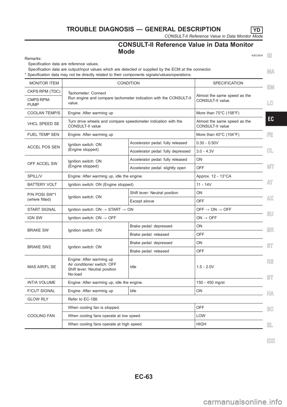
CONSULT-II Reference Value in Data Monitor
Mode
NJEC0634Remarks:
Specification data are reference values.
Specification data are output/input values which are detected or supplied by the ECM at the connector.
* Specification data may not be directly related to their components signals/values/operations.
MONITOR ITEM CONDITION SPECIFICATION
CKPS·RPM (TDC)
Tachometer: Connect
Run engine and compare tachometer indication with the CONSULT-II
value.Almost the same speed as the
CONSULT-II value. CMPS·RPM-
PUMP
COOLAN TEMP/S Engine: After warming up More than 70°C (158°F)
VHCL SPEED SETurn drive wheels and compare speedometer indication with the
CONSULT-II valueAlmost the same speed as the
CONSULT-II value
FUEL TEMP SEN Engine: After warming up More than 40°C (104°F)
ACCEL POS SENIgnition switch: ON
(Engine stopped)Accelerator pedal: fully released 0.30 - 0.50V
Accelerator pedal: fully depressed 3.0 - 4.3V
OFF ACCEL SWIgnition switch: ON
(Engine stopped)Accelerator pedal: fully released ON
Accelerator pedal: slightly open OFF
SPILL/V Engine: After warming up, idle the engine. Approx. 12 - 13°CA
BATTERY VOLT Ignition switch: ON (Engine stopped) 11 - 14V
P/N POSI SW*1
(where fitted)Ignition switch: ONShift lever: Neutral position ON
Except above OFF
START SIGNAL Ignition switch: ON,START,ON OFF,ON,OFF
IGN SW Ignition switch: ON,OFF ON,OFF
BRAKE SW Ignition switch: ONBrake pedal: depressed ON
Brake pedal: released OFF
BRAKE SW2 Ignition switch: ONBrake pedal: depressed ON
Brake pedal: released OFF
MAS AIR/FL SEEngine: After warming up
Air conditioner switch: OFF
Shift lever: Neutral position
No-loadIdle 1.5 - 2.0V
INT/A VOLUME Engine: After warming up, idle the engine. 150 - 450 mg/st
F/CUT SIGNAL Engine: After warming up Idle ON
GLOW RLY Refer to EC-188.
COOLING FANWhen cooling fan is stopped. OFF
When cooling fans operate at low speed. LOW
When cooling fans operate at high speed. HIGH
GI
MA
EM
LC
FE
CL
MT
AT
AX
SU
BR
ST
RS
BT
HA
SC
EL
IDX
TROUBLE DIAGNOSIS — GENERAL DESCRIPTIONYD
CONSULT-II Reference Value in Data Monitor Mode
EC-63
Page 1118 of 3189
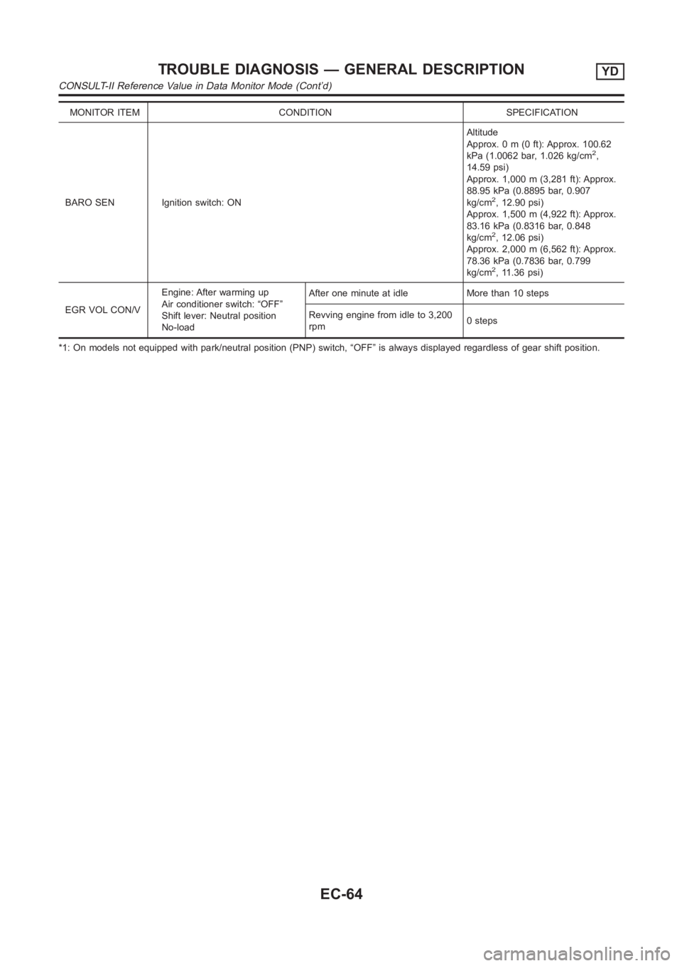
MONITOR ITEM CONDITION SPECIFICATION
BARO SEN Ignition switch: ONAltitude
Approx. 0 m (0 ft): Approx. 100.62
kPa (1.0062 bar, 1.026 kg/cm
2,
14.59 psi)
Approx. 1,000 m (3,281 ft): Approx.
88.95 kPa (0.8895 bar, 0.907
kg/cm
2, 12.90 psi)
Approx. 1,500 m (4,922 ft): Approx.
83.16 kPa (0.8316 bar, 0.848
kg/cm
2, 12.06 psi)
Approx. 2,000 m (6,562 ft): Approx.
78.36 kPa (0.7836 bar, 0.799
kg/cm
2, 11.36 psi)
EGR VOL CON/VEngine: After warming up
Air conditioner switch: “OFF”
Shift lever: Neutral position
No-loadAfter one minute at idle More than 10 steps
Revving engine from idle to 3,200
rpm0steps
*1: On models not equipped with park/neutral position (PNP) switch, “OFF”is always displayed regardless of gear shift position.
TROUBLE DIAGNOSIS — GENERAL DESCRIPTIONYD
CONSULT-II Reference Value in Data Monitor Mode (Cont’d)
EC-64
Page 1121 of 3189
![NISSAN ALMERA N16 2003 Electronic Repair Manual TERMI-
NAL
NO.WIRE
COLORITEM CONDITIONDATA (DC Voltage and Pulse
Signal)
204 L Air conditioner relay[Engine is running]
Air conditioner switch is “OFF”BATTERY VOLTAGE
(11 - 14V)
[Engine is running NISSAN ALMERA N16 2003 Electronic Repair Manual TERMI-
NAL
NO.WIRE
COLORITEM CONDITIONDATA (DC Voltage and Pulse
Signal)
204 L Air conditioner relay[Engine is running]
Air conditioner switch is “OFF”BATTERY VOLTAGE
(11 - 14V)
[Engine is running](/manual-img/5/57350/w960_57350-1120.png)
TERMI-
NAL
NO.WIRE
COLORITEM CONDITIONDATA (DC Voltage and Pulse
Signal)
204 L Air conditioner relay[Engine is running]
Air conditioner switch is “OFF”BATTERY VOLTAGE
(11 - 14V)
[Engine is running]
Both air conditioner switch and blower fan
switch are “ON”
(Compressor is operating)Approximately 0.1V
214 W/B Glow relay Refer to “Glow Control System”, EC-188.
218 B Sensors’ ground[Engine is running]
Warm-up condition
Idle speedApproximately 0V
219 LG/R Cooling fan relay (Low)[Engine is running]
Cooling fan is not operatingBATTERY VOLTAGE
(11 - 14V)
[Engine is running]
Cooling fan is operatingApproximately 0.1V
221 LG/B Cooling fan relay (High)[Engine is running]
Cooling fan is not operating
Cooling fan is operating at low speedBATTERY VOLTAGE
(11 - 14V)
[Engine is running]
Cooling fan is operating at high speedApproximately 0.1V
223 WMass air flow sensor
power supply[Ignition switch “ON”]Approximately 5V
224 R Mass air flow sensor[Engine is running]
Warm-up condition
Idle speed1.5 - 2.0V
313 L/WElectronic control fuel
injection pump[Engine is running]
Warm-up condition
Idle speedApproximately 0.1V
314 L/RElectronic control fuel
injection pump[Engine is running]
Warm-up condition
Idle speedApproximately 0.4V
316 PUElectronic control fuel
injection pump[Engine is running]
Warm-up condition
Idle speedApproximately 2.5V
317 PElectronic control fuel
injection pump[Engine is running]
Warm-up condition
Idle speedApproximately 2.5V
325 G ECM relay (Self-shutoff)[Ignition switch “ON”]
[Ignition switch “OFF”]
For a few seconds after turning ignition switch
“OFF”Approximately 0.25V
[Ignition switch “OFF”]
A few seconds passed after turning ignition
switch “OFF”BATTERY VOLTAGE
(11 - 14V)
331 ORCrankshaft position sen-
sor (TDC) ground[Engine is running]
Warm-up condition
Idle speedApproximately 0V
334 B/REngine coolant tempera-
ture sensor ground[Ignition switch “ON”]Approximately 0V
GI
MA
EM
LC
FE
CL
MT
AT
AX
SU
BR
ST
RS
BT
HA
SC
EL
IDX
TROUBLE DIAGNOSIS — GENERAL DESCRIPTIONYD
ECM Terminals and Reference Value (Cont’d)
EC-67