2003 NISSAN ALMERA N16 Air conditioner
[x] Cancel search: Air conditionerPage 2116 of 3189
ATC-136
REFRIGERANT LINES
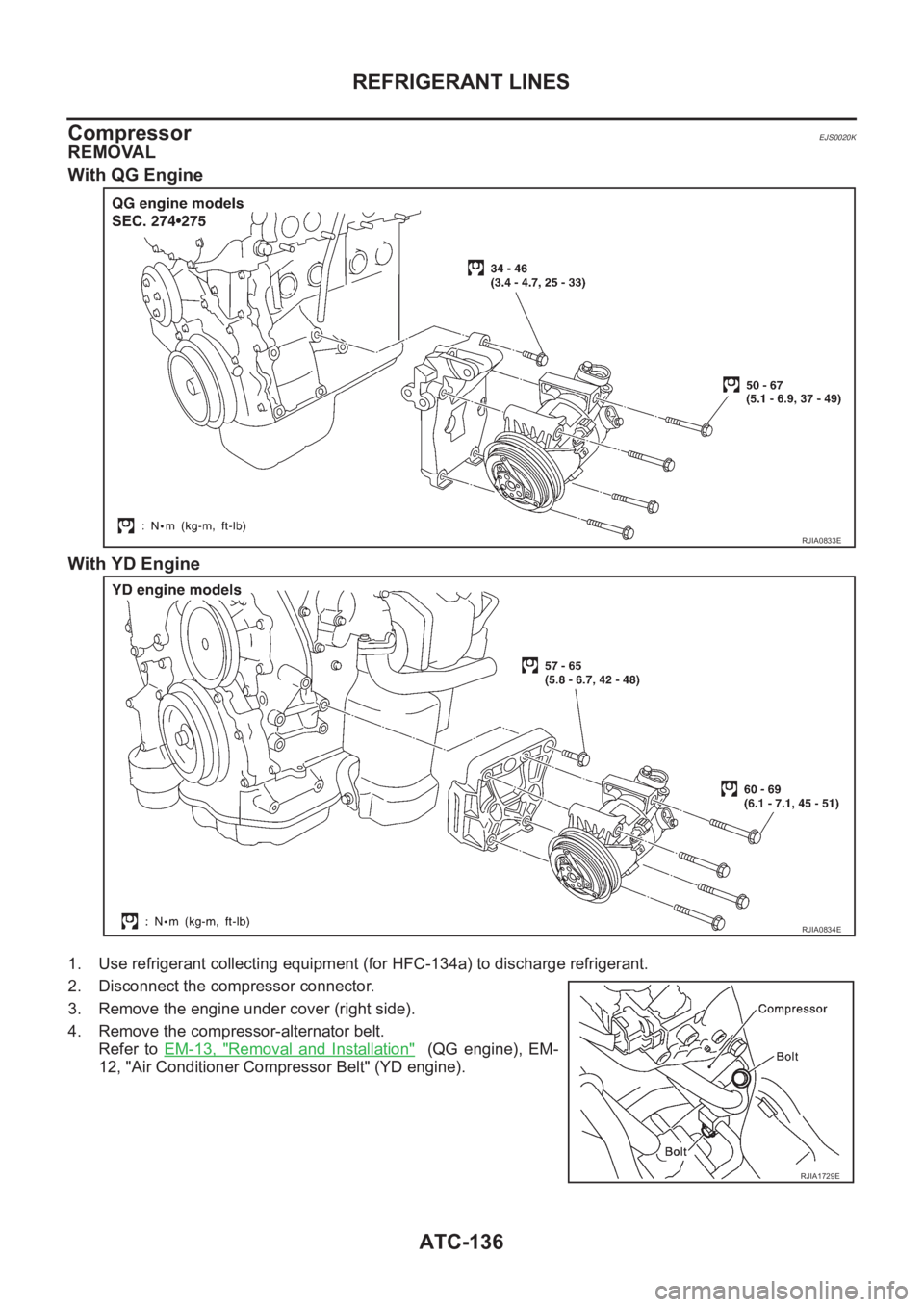
Compressor
EJS0020K
REMOVAL
With QG Engine
With YD Engine
1. Use refrigerant collecting equipment (for HFC-134a) to discharge refrigerant.
2. Disconnect the compressor connector.
3. Remove the engine under cover (right side).
4. Remove the compressor-alternator belt.
Refer to EM-13, "
Removal and Installation" (QG engine), EM-
12, "Air Conditioner Compressor Belt" (YD engine).
RJIA0833E
RJIA0834E
RJIA1729E
Page 2713 of 3189
![NISSAN ALMERA N16 2003 Electronic Repair Manual Terminal
No.Wire
colorConnections Operated condition Voltage (Approximate values)
24 BRWasher switch
(Headlamp washer switch)[Head lamp switch 1st or 2nd posi-
tion]
Washer switch OFF,ON12V,0V
25 G/OR NISSAN ALMERA N16 2003 Electronic Repair Manual Terminal
No.Wire
colorConnections Operated condition Voltage (Approximate values)
24 BRWasher switch
(Headlamp washer switch)[Head lamp switch 1st or 2nd posi-
tion]
Washer switch OFF,ON12V,0V
25 G/OR](/manual-img/5/57350/w960_57350-2712.png)
Terminal
No.Wire
colorConnections Operated condition Voltage (Approximate values)
24 BRWasher switch
(Headlamp washer switch)[Head lamp switch 1st or 2nd posi-
tion]
Washer switch OFF,ON12V,0V
25 G/ORCombination switch
(Turn signal switch)Turn signal switch:
Neutral,Left turn position12V,0V
26 L/BCombination switch
(Turn signal switch)Turn signal switch:
Neutral,Right turn position12V,0V
27 Y/BVehicle security horn relay
(RHD models)When theft warning system:
Armed,Disarmed0V,12V
28 R/Y Interior room lampWhen interior lamp is operated using
remote controller (Lamp switch in
“DOOR” position)12V,0V
29 Y/G Ignition key switch Ignition key is in “ON” position 12V
30 G/R Hazard switch Hazard switch: OFF,ON 12V,0V
31 W Rear window defogger relay[Ignition switch “ON”]
Rear window defogger switch:
OFF,ON12V,0V
32 LG/B Cooling fan relay[Ignition switch“ ON”]
Cooling fan: Operating,Not operat-
ing0V,12V
33 LG/R Cooling fan relay[Ignition switch “ON”]
Cooling fan: Operating,Not operat-
ing0V,12V
34 L/Y Security indicator Ignition switch ON,OFF 12V,0V
39 BR/WRear door switch
(Passenger side)Rear door LH or RH: Open,Closed 0V,12V
41 L Air conditioner relay[Engine is running]
Air conditioner switch: ON,
OFF12V,0V
43 R/WFront door switch
(Driver side)Front door (Driver side):
Open,Closed12V,0V
44 R/WFront door switch
(Passenger side)Front door (Passenger side):
Open,Closed0V,12V
45 R/YRear door switch
(Driver side)Rear door LH or RH: Open,Closed 0V,12V
49 W/L Power source — 12V
50 GPower door super lock actuator
(Rear)Remote controller door lock switch:
Free,Press0V,12V
51 L/R Driver door lock actuatorDoor lock & unlock switch:
Free,Lock0V,12V
52 W/R Door lock actuatorsDoor lock & unlock switch:
Free,Unlock0V,12V
53 B Ground — 0V
54 R/B Door lock actuatorsDoor lock & unlock switch:
Free,Unlock0V,12V
55 W/BPower door super lock actuator
(Front)Remote controller door lock switch:
Free,Unlock0V,12V
56 R/B Power source — 12V
GI
MA
EM
LC
EC
FE
CL
MT
AT
AX
SU
BR
ST
RS
BT
HA
SC
IDX
SMART ENTRANCE CONTROL SYSTEM
Smart Entrance Control Unit Inspection Table (Cont’d)
EL-377
Page 2802 of 3189
Error itemPossible causes
Example of symptom
Action/symptom
GPS antenna
disconnectedMalfunctioning connection between GPS substrate in AV and
NAVI control unit and GPS antenna.Navigation location detection performance
has deteriorated.
(Location correction using GPS is not per-
formed.)
GPS receiving status remains gray. Perform the self-diagnosis.
When connection between AV and NAVI control unit and GPS
antenna is judged normal by self-diagnosis, the symptom may
be intermittent, caused by impact or vibration.
Low voltage
of GPSThe power voltage supplied to the GPS circuit board has
decreased.Navigation location detection performance
has deteriorated.
(Location correction using GPS is not per-
formed.)
GPS receiving status remains gray. Perform the self-diagnosis.
When connection between AV and NAVI control unit and GPS
antenna is judged normal by self-diagnosis, the symptom may
be intermittent, caused by impact or vibration.
DVD-ROM
Malfunction
DVD-ROM
Read error
DVD-ROM
Response
ErrorMalfunctioning AV and NAVI control unit -
Dedicated map DVD-ROM is in the system, but the data cannot
be read.
The map of a particular location cannot be
displayed.
Specific guidance information cannot be dis-
played.
Map display is slow.
Guidance information display is slow.
System has been affected by vibration. Is map DVD-ROM damaged, warped, or dirty?
– If damaged or warped, the map DVD-ROM is malfunctioning.
– If dirty, wipe the DVD-ROM clean with a soft cloth.
Perform the self-diagnosis.
When AV and NAVI control unit is judged normal by self-
diagnosis, the symptom is judged intermittent, caused by
vibration.
AUTO CLIMATE CONTROLNJEL0604S07“ATC Automatic Air Conditioner” ATC-42, “Self-diagnosis Func-
tion” for the details.
SKIA1621E
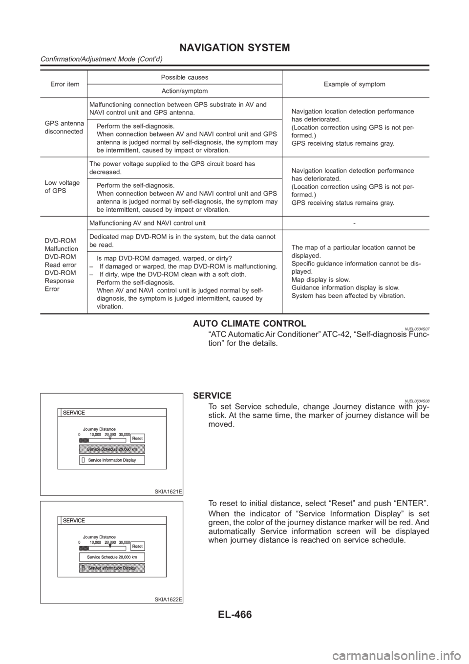
SERVICENJEL0604S08To set Service schedule, change Journey distance with joy-
stick. At the same time, the marker of journey distance will be
moved.
SKIA1622E
To reset to initial distance, select “Reset” and push “ENTER”.
When the indicator of “Service Information Display” is set
green, the color of the journey distance marker will be red. And
automatically Service information screen will be displayed
when journey distance is reached on service schedule.
NAVIGATION SYSTEM
Confirmation/Adjustment Mode (Cont’d)
EL-466
Page 2846 of 3189
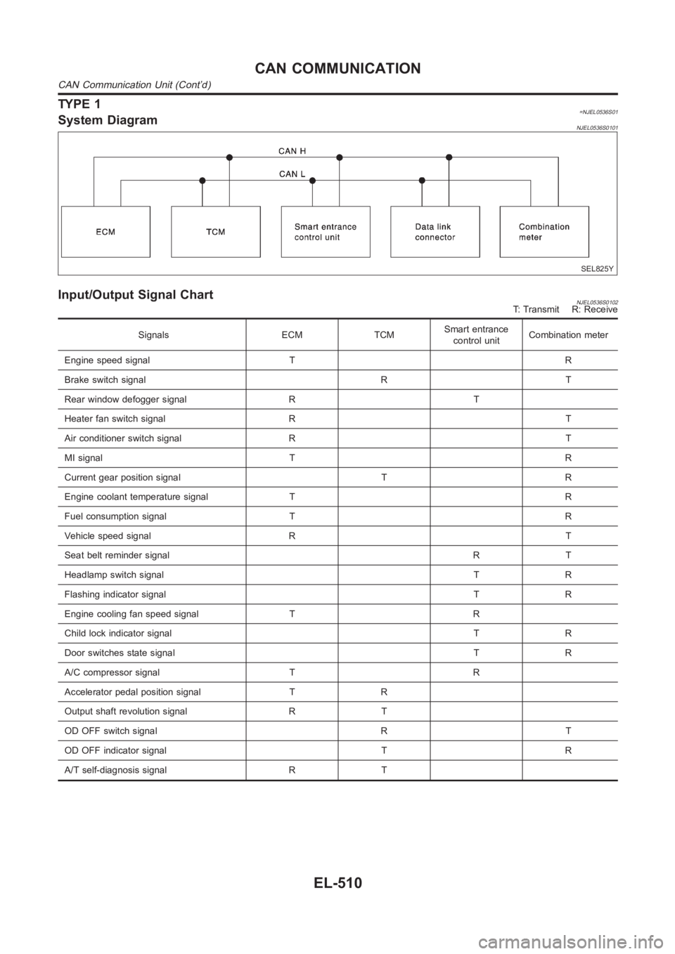
TYPE 1=NJEL0536S01System DiagramNJEL0536S0101
SEL825Y
Input/Output Signal ChartNJEL0536S0102T: Transmit R: Receive
Signals ECM TCMSmart entrance
control unitCombination meter
Engine speed signal T R
Brake switch signal R T
Rear window defogger signal R T
Heater fan switch signal R T
Air conditioner switch signal R T
MI signal T R
Current gear position signal T R
Engine coolant temperature signal T R
Fuel consumption signal T R
Vehicle speed signal R T
Seat belt reminder signalRT
Headlamp switch signalTR
Flashing indicator signalTR
Engine cooling fan speed signal T R
Child lock indicator signalTR
Door switches state signal T R
A/C compressor signal T R
Accelerator pedal position signal T R
Output shaft revolution signal R T
OD OFF switch signal R T
OD OFF indicator signal T R
A/T self-diagnosis signal R T
CAN COMMUNICATION
CAN Communication Unit (Cont’d)
EL-510
Page 2847 of 3189
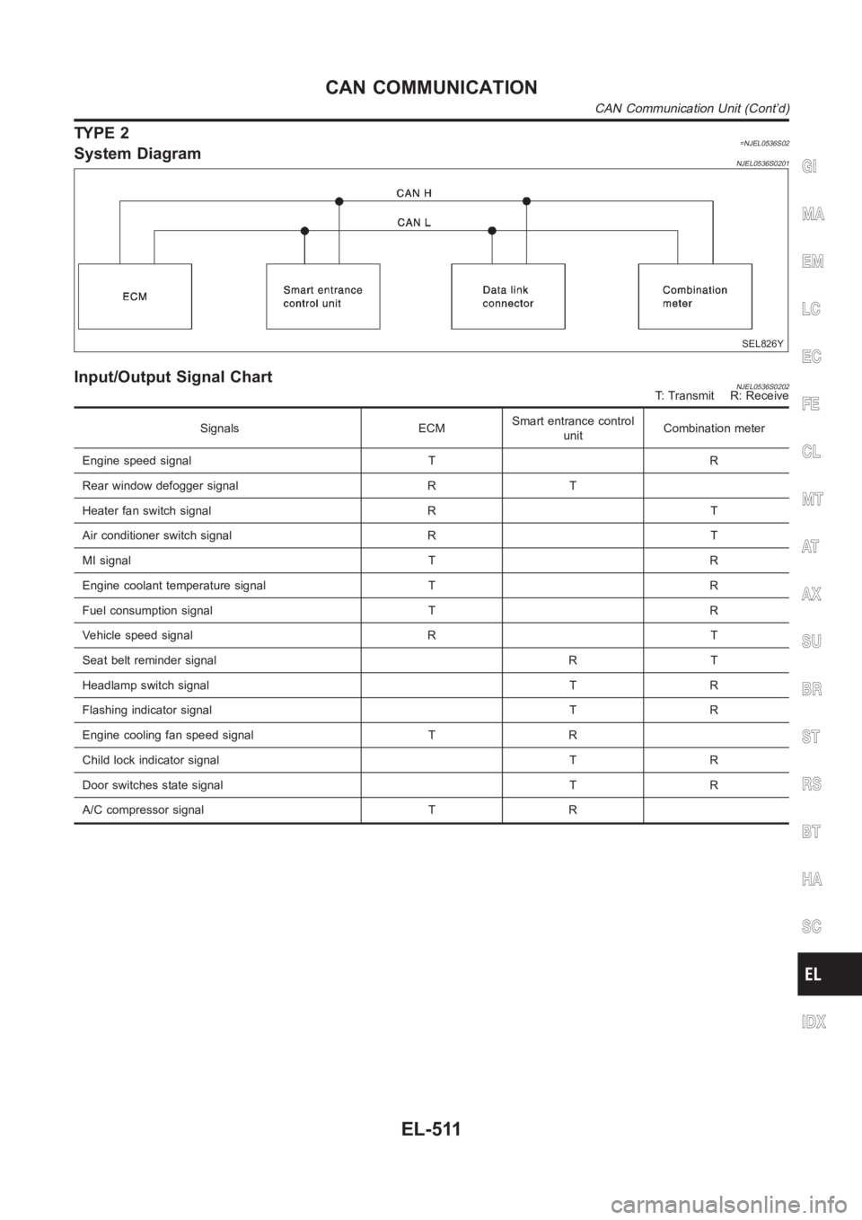
TYPE 2=NJEL0536S02System DiagramNJEL0536S0201
SEL826Y
Input/Output Signal ChartNJEL0536S0202T: Transmit R: Receive
Signals ECMSmart entrance control
unitCombination meter
Engine speed signal T R
Rear window defogger signal R T
Heater fan switch signal R T
Air conditioner switch signal R T
MI signal T R
Engine coolant temperature signal T R
Fuel consumption signal T R
Vehicle speed signal R T
Seat belt reminder signal R T
Headlamp switch signal T R
Flashing indicator signal T R
Engine cooling fan speed signal T R
Child lock indicator signal T R
Door switches state signal T R
A/C compressor signal T R
GI
MA
EM
LC
EC
FE
CL
MT
AT
AX
SU
BR
ST
RS
BT
HA
SC
IDX
CAN COMMUNICATION
CAN Communication Unit (Cont’d)
EL-511
Page 2935 of 3189
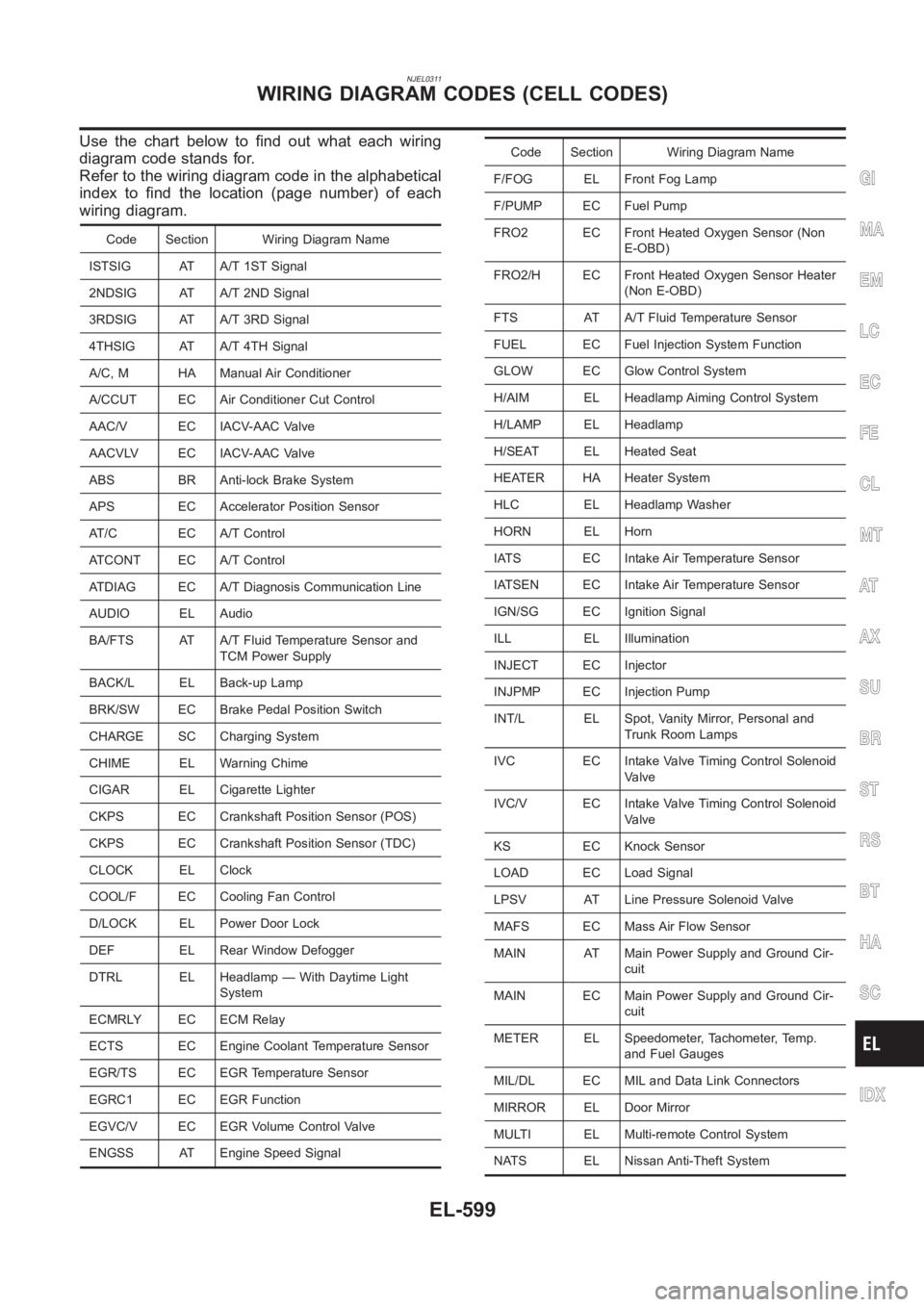
NJEL0311
Use the chart below to find out what each wiring
diagram code stands for.
Refer to the wiring diagram code in the alphabetical
index to find the location (page number) of each
wiring diagram.
Code Section Wiring Diagram Name
ISTSIG AT A/T 1ST Signal
2NDSIG AT A/T 2ND Signal
3RDSIG AT A/T 3RD Signal
4THSIG AT A/T 4TH Signal
A/C, M HA Manual Air Conditioner
A/CCUT EC Air Conditioner Cut Control
AAC/V EC IACV-AAC Valve
AACVLV EC IACV-AAC Valve
ABS BR Anti-lock Brake System
APS EC Accelerator Position Sensor
AT/C EC A/T Control
ATCONT EC A/T Control
ATDIAG EC A/T Diagnosis Communication Line
AUDIO EL Audio
BA/FTS AT A/T Fluid Temperature Sensor and
TCM Power Supply
BACK/L EL Back-up Lamp
BRK/SW EC Brake Pedal Position Switch
CHARGE SC Charging System
CHIME EL Warning Chime
CIGAR EL Cigarette Lighter
CKPS EC Crankshaft Position Sensor (POS)
CKPS EC Crankshaft Position Sensor (TDC)
CLOCK EL Clock
COOL/F EC Cooling Fan Control
D/LOCK EL Power Door Lock
DEF EL Rear Window Defogger
DTRL EL Headlamp — With Daytime Light
System
ECMRLY EC ECM Relay
ECTS EC Engine Coolant Temperature Sensor
EGR/TS EC EGR Temperature Sensor
EGRC1 EC EGR Function
EGVC/V EC EGR Volume Control Valve
ENGSS AT Engine Speed Signal
Code Section Wiring Diagram Name
F/FOG EL Front Fog Lamp
F/PUMP EC Fuel Pump
FRO2 EC Front Heated Oxygen Sensor (Non
E-OBD)
FRO2/H EC Front Heated Oxygen Sensor Heater
(Non E-OBD)
FTS AT A/T Fluid Temperature Sensor
FUEL EC Fuel Injection System Function
GLOW EC Glow Control System
H/AIM EL Headlamp Aiming Control System
H/LAMP EL Headlamp
H/SEAT EL Heated Seat
HEATER HA Heater System
HLC EL Headlamp Washer
HORN EL Horn
IATS EC Intake Air Temperature Sensor
IATSEN EC Intake Air Temperature Sensor
IGN/SG EC Ignition Signal
ILL EL Illumination
INJECT EC Injector
INJPMP EC Injection Pump
INT/L EL Spot, Vanity Mirror, Personal and
Trunk Room Lamps
IVC EC Intake Valve Timing Control Solenoid
Valve
IVC/V EC Intake Valve Timing Control Solenoid
Valve
KS EC Knock Sensor
LOAD EC Load Signal
LPSV AT Line Pressure Solenoid Valve
MAFS EC Mass Air Flow Sensor
MAIN AT Main Power Supply and Ground Cir-
cuit
MAIN EC Main Power Supply and Ground Cir-
cuit
METER EL Speedometer, Tachometer, Temp.
and Fuel Gauges
MIL/DL EC MIL and Data Link Connectors
MIRROR EL Door Mirror
MULTI EL Multi-remote Control System
NATS EL Nissan Anti-Theft System
GI
MA
EM
LC
EC
FE
CL
MT
AT
AX
SU
BR
ST
RS
BT
HA
SC
IDX
WIRING DIAGRAM CODES (CELL CODES)
EL-599
Page 2937 of 3189
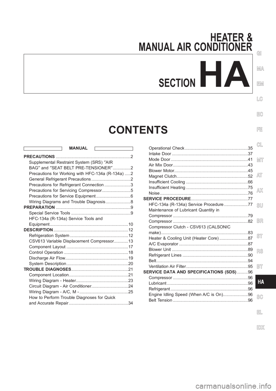
HEATER &
MANUAL AIR CONDITIONER
SECTION
HA
CONTENTS
MANUAL
PRECAUTIONS<0011001100110011001100110011001100110011001100110011001100110011001100110011001100110011001100110011001100110011001100110011001100110011001100110011001100110011001100110011001100110011001100110011001100
11001100110011001100110011001100110011001100110011[2
Supplemental Restraint System (SRS)″AIR
BAG″and″SEAT BELT PRE-TENSIONER″...............2
Precautions for Working with HFC-134a (R-134a) .....2
General Refrigerant Precautions .................................2
Precautions for Refrigerant Connection ......................3
Precautions for Servicing Compressor ........................5
Precautions for Service Equipment .............................6
Wiring Diagrams and Trouble Diagnosis .....................8
PREPARATION<0011001100110011001100110011001100110011001100110011001100110011001100110011001100110011001100110011001100110011001100110011001100110011001100110011001100110011001100110011001100110011001100110011001100
11001100110011001100110011001100110011001100110011[9
Special Service Tools ..................................................9
HFC-134a (R-134a) Service Tools and
Equipment <0011001100110011001100110011001100110011001100110011001100110011001100110011001100110011001100110011001100110011001100110011001100110011001100110011001100110011001100110011001100110011001100110011001100
11001100110011[............10
DESCRIPTION<0011001100110011001100110011001100110011001100110011001100110011001100110011001100110011001100110011001100110011001100110011001100110011001100110011001100110011001100110011001100110011001100110011001100
11001100110011001100110011001100110011001100110011[12
Refrigeration System .................................................12
CSV613 Variable Displacement Compressor............13
Component Layout ....................................................17
Control Operation ......................................................18
Discharge Air Flow.....................................................19
System Description ....................................................20
TROUBLE DIAGNOSES................................................21
Component Location..................................................21
Wiring Diagram - Heater............................................23
Circuit Diagram - Air Conditioner...............................24
Wiring Diagram - A/C, M - .........................................25
How to Perform Trouble Diagnoses for Quick
and Accurate Repair ..................................................34Operational Check .....................................................35
Intake Door <0011001100110011001100110011001100110011001100110011001100110011001100110011001100110011001100110011001100110011001100110011001100110011001100110011001100110011001100110011001100110011001100110011001100
1100110011[...........37
Mode Door <0011001100110011001100110011001100110011001100110011001100110011001100110011001100110011001100110011001100110011001100110011001100110011001100110011001100110011001100110011001100110011001100110011001100
110011001100110011[..........41
Air Mix Door <0011001100110011001100110011001100110011001100110011001100110011001100110011001100110011001100110011001100110011001100110011001100110011001100110011001100110011001100110011001100110011001100110011001100
1100110011[..........43
Blower Motor<0011001100110011001100110011001100110011001100110011001100110011001100110011001100110011001100110011001100110011001100110011001100110011001100110011001100110011001100110011001100110011001100110011001100
110011[..........45
Magnet Clutch<0011001100110011001100110011001100110011001100110011001100110011001100110011001100110011001100110011001100110011001100110011001100110011001100110011001100110011001100110011001100110011001100110011001100
11[.........52
Insufficient Cooling ....................................................66
Insufficient Heating ....................................................75
Noise <0011001100110011001100110011001100110011001100110011001100110011001100110011001100110011001100110011001100110011001100110011001100110011001100110011001100110011001100110011001100110011001100110011001100
110011001100110011001100110011[................76
SERVICE PROCEDURE................................................77
HFC-134a (R-134a) Service Procedure ....................77
Maintenance of Lubricant Quantity in
Compressor <0011001100110011001100110011001100110011001100110011001100110011001100110011001100110011001100110011001100110011001100110011001100110011001100110011001100110011001100110011001100110011001100110011001100
1100110011[..........79
Compressor <0011001100110011001100110011001100110011001100110011001100110011001100110011001100110011001100110011001100110011001100110011001100110011001100110011001100110011001100110011001100110011001100110011001100
1100110011[..........82
Compressor Clutch - CSV613 (CALSONIC
make) <0011001100110011001100110011001100110011001100110011001100110011001100110011001100110011001100110011001100110011001100110011001100110011001100110011001100110011001100110011001100110011001100110011001100
110011001100110011001100110011[...............83
Heater & Cooling Unit (Heater Core) ........................87
A/C Evaporator ..........................................................87
Blower Unit <0011001100110011001100110011001100110011001100110011001100110011001100110011001100110011001100110011001100110011001100110011001100110011001100110011001100110011001100110011001100110011001100110011001100
1100110011[...........89
Refrigerant Lines .......................................................90
Belt <0011001100110011001100110011001100110011001100110011001100110011001100110011001100110011001100110011001100110011001100110011001100110011001100110011001100110011001100110011001100110011001100110011001100
1100110011001100110011001100110011[..................94
Ventilation Air Filter ....................................................95
SERVICE DATA AND SPECIFICATIONS (SDS).........96
Compressor <0011001100110011001100110011001100110011001100110011001100110011001100110011001100110011001100110011001100110011001100110011001100110011001100110011001100110011001100110011001100110011001100110011001100
1100110011[..........96
Lubricant <0011001100110011001100110011001100110011001100110011001100110011001100110011001100110011001100110011001100110011001100110011001100110011001100110011001100110011001100110011001100110011001100110011001100
11001100110011[..............96
Refrigerant <0011001100110011001100110011001100110011001100110011001100110011001100110011001100110011001100110011001100110011001100110011001100110011001100110011001100110011001100110011001100110011001100110011001100
110011[.............96
Engine Idling Speed (When A/C is On).....................96
Belt Tension <0011001100110011001100110011001100110011001100110011001100110011001100110011001100110011001100110011001100110011001100110011001100110011001100110011001100110011001100110011001100110011001100110011001100
110011[...........96
GI
MA
EM
LC
EC
FE
CL
MT
AT
AX
SU
BR
ST
RS
BT
SC
EL
IDX
Page 2941 of 3189
When installing an air conditioner in the vehicle, connect the pipes as thefinal stage of the opera-
tion. Do not remove the seal caps of pipes and other components until just before required for
connection.
Allow components stored in cool areas to warm to working area temperature before removing seal
caps. This prevents condensation from forming inside A/C components.
Thoroughly remove moisture from the refrigeration system before charging the refrigerant.
Always replace used O-rings.
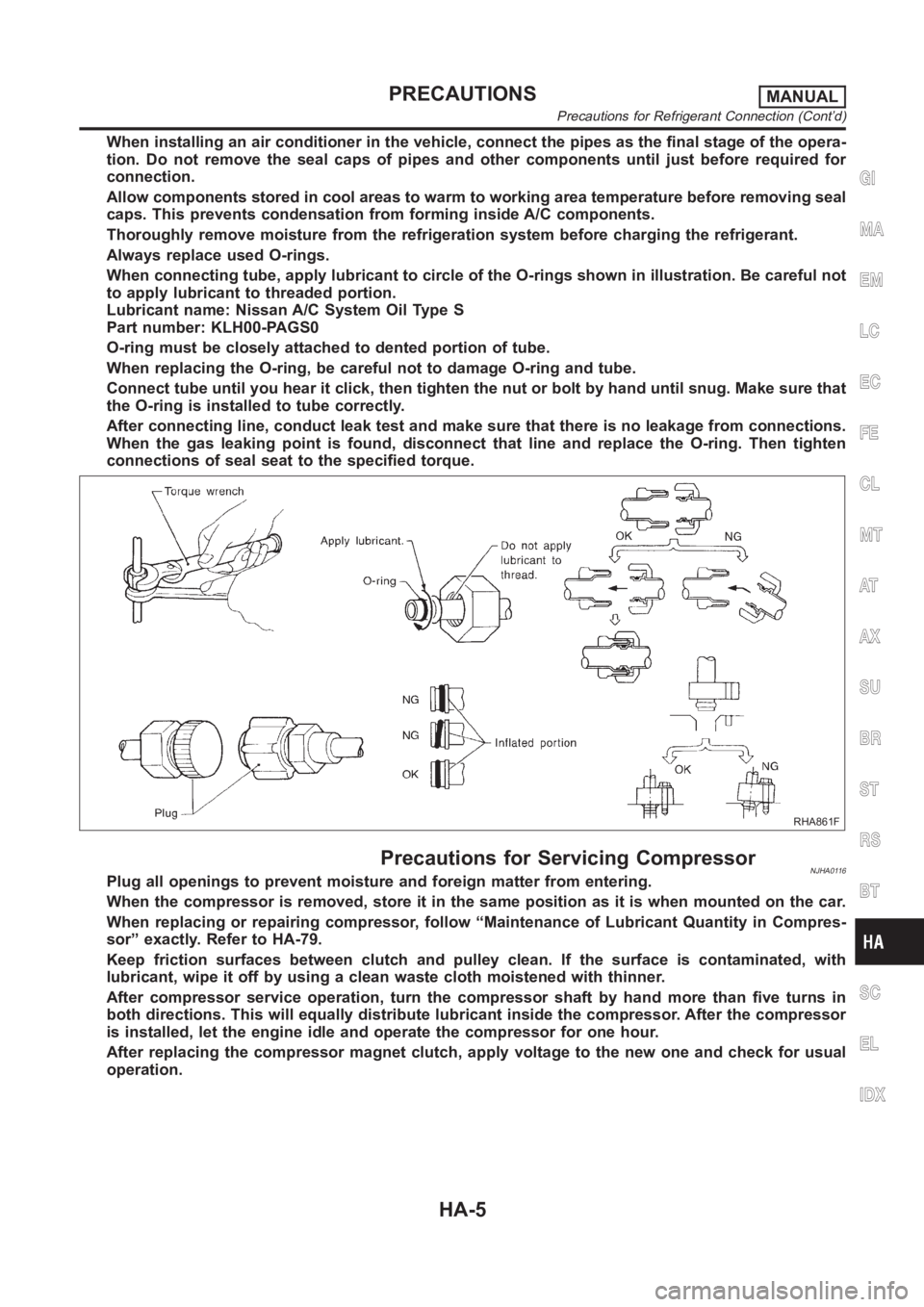
When connecting tube, apply lubricant to circle of the O-rings shown in illustration. Be careful not
to apply lubricant to threaded portion.
Lubricant name: Nissan A/C System Oil Type S
Part number: KLH00-PAGS0
O-ring must be closely attached to dented portion of tube.
When replacing the O-ring, be careful not to damage O-ring and tube.
Connect tube until you hear it click, then tighten the nut or bolt by hand until snug. Make sure that
the O-ring is installed to tube correctly.
After connecting line, conduct leak test and make sure that there is no leakage from connections.
When the gas leaking point is found, disconnect that line and replace the O-ring. Then tighten
connections of seal seat to the specified torque.
RHA861F
Precautions for Servicing CompressorNJHA0116Plug all openings to prevent moisture and foreign matter from entering.
When the compressor is removed, store it in the same position as it is when mounted on the car.
When replacing or repairing compressor, follow “Maintenance of Lubricant Quantity in Compres-
sor” exactly. Refer to HA-79.
Keep friction surfaces between clutch and pulley clean. If the surface is contaminated, with
lubricant, wipe it off by using a clean waste cloth moistened with thinner.
After compressor service operation, turn the compressor shaft by hand more than five turns in
both directions. This will equally distribute lubricant inside the compressor. After the compressor
is installed, let the engine idle and operate the compressor for one hour.
After replacing the compressor magnet clutch, apply voltage to the new oneand check for usual
operation.
GI
MA
EM
LC
EC
FE
CL
MT
AT
AX
SU
BR
ST
RS
BT
SC
EL
IDX
PRECAUTIONSMANUAL
Precautions for Refrigerant Connection (Cont’d)
HA-5