2003 NISSAN ALMERA N16 Air conditioner
[x] Cancel search: Air conditionerPage 2954 of 3189
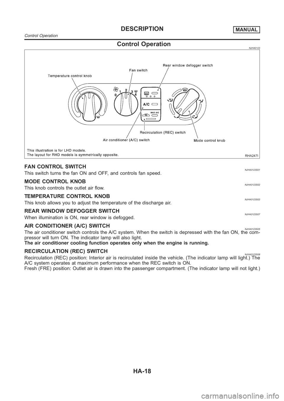
Control OperationNJHA0123
RHA247I
FAN CONTROL SWITCHNJHA0123S01This switch turns the fan ON and OFF, and controls fan speed.
MODE CONTROL KNOBNJHA0123S02This knob controls the outlet air flow.
TEMPERATURE CONTROL KNOBNJHA0123S03This knob allows you to adjust the temperature of the discharge air.
REAR WINDOW DEFOGGER SWITCHNJHA0123S07When illumination is ON, rear window is defogged.
AIR CONDITIONER (A/C) SWITCHNJHA0123S05The air conditioner switch controls the A/C system. When the switch is depressed with the fan ON, the com-
pressor will turn ON. The indicator lamp will also light.
The air conditioner cooling function operates only when the engine is running.
RECIRCULATION (REC) SWITCHNJHA0123S08Recirculation (REC) position: Interior air is recirculated inside the vehicle. (The indicator lamp will light.) The
A/C system operates at maximum performance when the REC switch is ON.
Fresh (FRE) position: Outlet air is drawn into the passenger compartment.(The indicator lamp will not light.)
DESCRIPTIONMANUAL
Control Operation
HA-18
Page 2960 of 3189
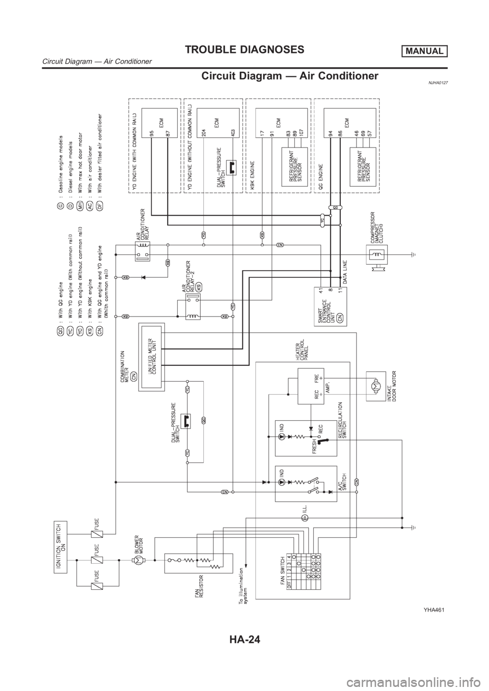
Circuit Diagram — Air ConditionerNJHA0127
YHA461
TROUBLE DIAGNOSESMANUAL
Circuit Diagram — Air Conditioner
HA-24
Page 2972 of 3189
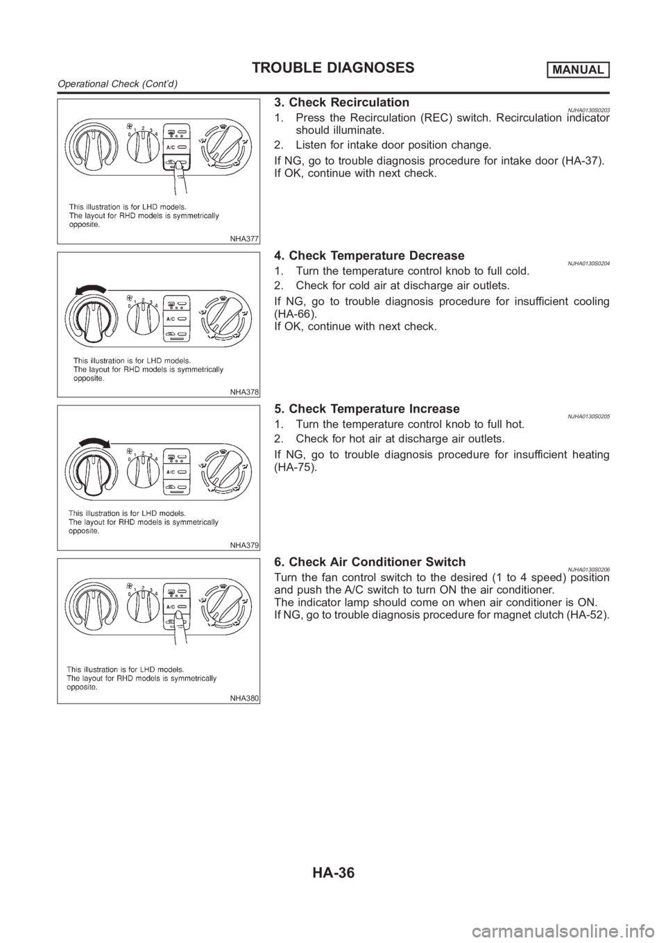
NHA377
3. Check RecirculationNJHA0130S02031. Press the Recirculation (REC) switch. Recirculation indicator
should illuminate.
2. Listen for intake door position change.
If NG, go to trouble diagnosis procedure for intake door (HA-37).
If OK, continue with next check.
NHA378
4. Check Temperature DecreaseNJHA0130S02041. Turn the temperature control knob to full cold.
2. Check for cold air at discharge air outlets.
If NG, go to trouble diagnosis procedure for insufficient cooling
(HA-66).
If OK, continue with next check.
NHA379
5. Check Temperature IncreaseNJHA0130S02051. Turn the temperature control knob to full hot.
2. Check for hot air at discharge air outlets.
If NG, go to trouble diagnosis procedure for insufficient heating
(HA-75).
NHA380
6. Check Air Conditioner SwitchNJHA0130S0206Turn the fan control switch to the desired (1 to 4 speed) position
and push the A/C switch to turn ON the air conditioner.
The indicator lamp should come on when air conditioner is ON.
If NG, go to trouble diagnosis procedure for magnet clutch (HA-52).
TROUBLE DIAGNOSESMANUAL
Operational Check (Cont’d)
HA-36
Page 3176 of 3189
A
A/C air flow (manual A/C) ..............................HA-19
A/C air flow <0011001100110011001100110011001100110011001100110011001100110011001100110011001100110011001100110011001100110011001100110011001100110011001100110011001100110011001100110011001100110011001100110011001100
110024>�TC-27
A/C component layout (manual A/C) .............HA-17
A/C compressor clutch removal and
installation (manual A/C).............................HA-82
A/C compressor clutch removal and
installation ...............................................ATC-139
A/C compressor precaution (manual
A/C) <0011001100110011001100110011001100110011001100110011001100110011001100110011001100110011001100110011001100110011001100110011001100110011001100110011001100110011001100110011001100110011001100110011001100
1100110011001100110011001100110011[....HA-5
A/C compressor precaution ............................ATC-7
A/C compressor special service tool
(manual A/C) .................................................HA-9
A/C compressor special service tool ............ATC-11
A/C control linkage adjustment (manual
A/C) <0011001100110011001100110011001100110011001100110011001100110011001100110011001100110011001100110011001100110011001100110011001100110011001100110011001100110011001100110011001100110011001100110011001100
1100110011001100110011001100110011[..HA-42
A/C control operation (manual A/C) ...............HA-18
A/C diagnostic work flow (manual A/C)..........HA-34
A/C evaporator (manual A/C) .........................HA-87
A/C HFC134a (R134a) system precau-
tion (manual A/C) ..........................................HA-2
A/C HFC134a (R134a) system
precaution <0011001100110011001100110011001100110011001100110011001100110011001100110011001100110011001100110011001100110011001100110011001100110011001100110011001100110011001100110011001100110011001100110011001100
110024>�TC-4
A/C HFC134a (R134a) system service
procedure (manual A/C) .............................HA-77
A/C HFC134a (R134a) system service
procedure ................................................ATC-133
A/C HFC134a (R134a) system service
tools (manual A/C) ......................................HA-10
A/C HFC134a (R134a) system service
tools<0011001100110011001100110011001100110011001100110011001100110011001100110011001100110011001100110011001100110011001100110011001100110011001100110011001100110011001100110011001100110011001100110011001100
110011001100110011001100110011[.ATC-11
A/C HFC134a system service equip-
ment precaution (manual A/C)......................HA-6
A/C HFC134a system service equip-
ment precaution ..........................................ATC-7
A/C lubricant (R134a) (manual A/C) ..............HA-79
A/C lubricant (R134a) ...................................ATC-20
A/C lubrication oil .......................................ATC-150
A/C operational check (manual A/C)..............HA-35
A/C operational check ..................................ATC-51
A/C performance chart (manual A/C).............HA-69
A/C performance test diagnoses
(manual A/C) ...............................................HA-67
A/C performance test diagnoses ..................ATC-89
A/C relay (manual A/C) ..................................HA-65
A/C reray <0011001100110011001100110011001100110011001100110011001100110011001100110011001100110011001100110011001100110011001100110011001100110011001100110011001100110011001100110011001100110011001100110011001100
110011001100110024[TC-85
A/C self-diagnoses (auto A/C) ......................ATC-42
A/C service data specification (manual
A/C) <0011001100110011001100110011001100110011001100110011001100110011001100110011001100110011001100110011001100110011001100110011001100110011001100110011001100110011001100110011001100110011001100110011001100
1100110011001100110011001100110011[..HA-96
A/C service data specification ....................ATC-150
A/C switch (manual A/C) ................................HA-65
A/C system description (auto A/C) ...............ATC-22
A/C trouble diagnoses (auto A/C) ................ATC-29
A/C, A - Wiring diagram................................ATC-33
A/C, M - Wiring diagram (manual A/C) ..........HA-25
A/CCUT - Wiring diagram (YD engine) ........EC-212
A/T - Wiring diagram - AT - FTS ...................AT-120
A/T - Wiring diagram - AT - MAIN .................AT-341A/T - Wiring diagram - AT - PNP/SW ............AT-114
A/T - Wiring diagram - AT -
VSS A/T........................................AT-127, AT-346
A/T fluid checking ............................................AT-13
A/T fluid replacement ......................................AT-13
A/T fluid temperature sensor.........................AT-123
A/T shift lock system - Wiring diagram .........AT-400
A/T shift lock system .....................................AT-399
A/T trouble diagnoses ........................AT-56, AT-256
A/T Wiring diagram - AT -
ENG SS........................................AT-131, AT-386
A/T Wiring diagram AT - 1ST ........................AT-137
A/T Wiring diagram AT - 2ND .......................AT-143
A/T Wiring diagram AT - 3RD .......................AT-149
A/T Wiring diagram AT - 4TH ........................AT-155
A/T Wiring diagram AT - BA/FTS.....AT-198, AT-380
A/T Wiring diagram AT - LPSV ........AT-167, AT-391
A/T Wiring diagram AT - OVRCSV ..AT-190, AT-370
A/T Wiring diagram AT - SSV/A.......AT-174, AT-360
A/T Wiring diagram AT - SSV/B.......AT-179, AT-365
A/T Wiring diagram AT - TCV ..........AT-162, AT-375
A/T Wiring diagram AT - TPS ..........AT-185, AT-355
A/T Wiring diagrawm AT -
VSSMTR ......................................AT-204, AT-351
ABS (anti-lock brake system).........................BR-45
ABS - Wiring diagram ....................................BR-50
ABS sensor rotor ............................................AX-24
Accelerator control system .........................FE-3, 14
Accelerator pedal position (APP) sen-
sor (QG engine) ..........EC-212, EC-219, EC-346,
EC-538, EC-545, EC-619
Accelerator pedal released position
learning (QG engine)....................EC-31, EC-426
Accelerator position sensor
(YD engine).................................................EC-89
Air bag disposal..............................................RS-35
Air bag precautions ...........................................GI-3
Air bag <0011001100110011001100110011001100110011001100110011001100110011001100110011001100110011001100110011001100110011001100110011001100110011001100110011001100110011001100110011001100110011001100110011001100
11001100110011001100110011[...RS-20
Air bleeding (hydraulic clutch) ........................CL-10
Air bleeding for brake system ..........................BR-8
Air cleaner and air duct (QG engine) ............EM-14
Air cleaner filter (QG engine).........................EM-14
Air conditioner cut control
(QG engine)..................................EC-26, EC-421
Air conditioner cut control (YD engine) ..........EC-19
Air flow meter - See Mass air flow sen-
sor (QG engine) .........................EC-135, EC-497
Air flow meter - See Mass air flow sen-
sor (YD engine) ..........................................EC-78
Air mix door control linkage adjustment
(manual A/C) ...............................................HA-44
Air mix door control linkage
adjustment ................................ATC-65, ATC-127
Air mix. door motor.......................ATC-63, ATC-127
Air spoiler, rear................................................BT-47
Alternator <0011001100110011001100110011001100110011001100110011001100110011001100110011001100110011001100110011001100110011001100110011001100110011001100110011001100110011001100110011001100110011001100110011001100
1100110011[...SC-30
Ambient sensor...........ATC-101, ATC-103, ATC-116
Angular tightening application
(QG engine)..................................................EM-3
Angular tightening application
(YD engine) ..................................................EM-3
ALPHABETICAL INDEX
IDX-2
Page 3177 of 3189
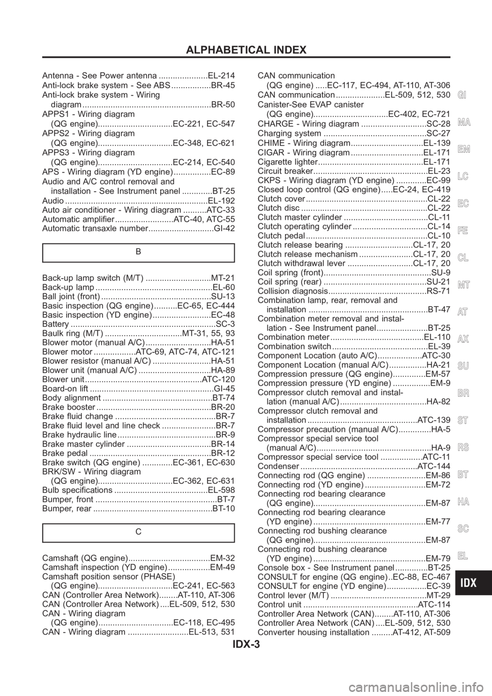
Antenna - See Power antenna .....................EL-214
Anti-lock brake system - See ABS .................BR-45
Anti-lock brake system - Wiring
diagram <0011001100110011001100110011001100110011001100110011001100110011001100110011001100110011001100110011001100110011001100110011001100110011001100110011001100110011001100110011001100110011001100110011001100
1100110011001100110025[R-50
APPS1 - Wiring diagram
(QG engine)................................EC-221, EC-547
APPS2 - Wiring diagram
(QG engine)................................EC-348, EC-621
APPS3 - Wiring diagram
(QG engine)................................EC-214, EC-540
APS - Wiring diagram (YD engine) ................EC-89
Audio and A/C control removal and
installation - See Instrument panel .............BT-25
Audio <0011001100110011001100110011001100110011001100110011001100110011001100110011001100110011001100110011001100110011001100110011001100110011001100110011001100110011001100110011001100110011001100110011001100
110011001100110011001100110011[...EL-192
Auto air conditioner - Wiring diagram ..........ATC-33
Automatic amplifier .........................ATC-40, ATC-55
Automatic transaxle number............................GI-42
B
Back-up lamp switch (M/T) ............................MT-21
Back-up lamp <0011001100110011001100110011001100110011001100110011001100110011001100110011001100110011001100110011001100110011001100110011001100110011001100110011001100110011001100110011001100110011001100110011001100
28002f[-60
Ball joint (front) ...............................................SU-13
Basic inspection (QG engine) ..........EC-65, EC-444
Basic inspection (YD engine) .........................EC-48
Battery <0011001100110011001100110011001100110011001100110011001100110011001100110011001100110011001100110011001100110011001100110011001100110011001100110011001100110011001100110011001100110011001100110011001100
1100110011001100110011[......SC-3
Baulk ring (M/T) .................................MT-31, 55, 93
Blower motor (manual A/C) ............................HA-51
Blower motor ..................ATC-69, ATC-74, ATC-121
Blower resistor (manual A/C) .........................HA-51
Blower unit (manual A/C) ...............................HA-89
Blower unit <0011001100110011001100110011001100110011001100110011001100110011001100110011001100110011001100110011001100110011001100110011001100110011001100110011001100110011001100110011001100110011001100110011001100
24>�7�C-120
Board-on lift <0011001100110011001100110011001100110011001100110011001100110011001100110011001100110011001100110011001100110011001100110011001100110011001100110011001100110011001100110011001100110011001100110011001100
11[..GI-45
Body alignment ...............................................BT-74
Brake booster .................................................BR-20
Brake fluid change ...........................................BR-7
Brake fluid level and line check .......................BR-7
Brake hydraulic line ..........................................BR-9
Brake master cylinder ....................................BR-14
Brake pedal <0011001100110011001100110011001100110011001100110011001100110011001100110011001100110011001100110011001100110011001100110011001100110011001100110011001100110011001100110011001100110011001100110011001100
1100110025[R-12
Brake switch (QG engine) .............EC-361, EC-630
BRK/SW - Wiring diagram
(QG engine)................................EC-362, EC-631
Bulb specifications ........................................EL-598
Bumper, front <0011001100110011001100110011001100110011001100110011001100110011001100110011001100110011001100110011001100110011001100110011001100110011001100110011001100110011001100110011001100110011001100110011001100
11[.BT-7
Bumper, rear <0011001100110011001100110011001100110011001100110011001100110011001100110011001100110011001100110011001100110011001100110011001100110011001100110011001100110011001100110011001100110011001100110011001100
110025[T- 1 0
C
Camshaft (QG engine)...................................EM-32
Camshaft inspection (YD engine) ..................EM-49
Camshaft position sensor (PHASE)
(QG engine)................................EC-241, EC-563
CAN (Controller Area Network)........AT-110, AT-306
CAN (Controller Area Network) ....EL-509, 512, 530
CAN - Wiring diagram
(QG engine) ................................EC-118, EC-495
CAN - Wiring diagram ..........................EL-513, 531CAN communication
(QG engine) .....EC-117, EC-494, AT-110, AT-306
CAN communication .....................EL-509, 512, 530
Canister-See EVAP canister
(QG engine)................................EC-402, EC-721
CHARGE - Wiring diagram ............................SC-28
Charging system ............................................SC-27
CHIME - Wiring diagram...............................EL-139
CIGAR - Wiring diagram ...............................EL-171
Cigarette lighter.............................................EL-171
Circuit breaker.................................................EL-23
CKPS - Wiring diagram (YD engine) .............EC-99
Closed loop control (QG engine) .....EC-24, EC-419
Clutch cover <0011001100110011001100110011001100110011001100110011001100110011001100110011001100110011001100110011001100110011001100110011001100110011001100110011001100110011001100110011001100110011001100110011001100
110011[CL-22
Clutch disc <0011001100110011001100110011001100110011001100110011001100110011001100110011001100110011001100110011001100110011001100110011001100110011001100110011001100110011001100110011001100110011001100110011001100
1100110011[.CL-22
Clutch master cylinder ....................................CL-11
Clutch operating cylinder ................................CL-14
Clutch pedal <0011001100110011001100110011001100110011001100110011001100110011001100110011001100110011001100110011001100110011001100110011001100110011001100110011001100110011001100110011001100110011001100110011001100
110011[CL-10
Clutch release bearing .............................CL-17, 20
Clutch release mechanism .......................CL-17, 20
Clutch withdrawal lever ............................CL-17, 20
Coil spring (front)..............................................SU-9
Coil spring (rear) ............................................SU-21
Collision diagnosis..........................................RS-71
Combination lamp, rear, removal and
installation <0011001100110011001100110011001100110011001100110011001100110011001100110011001100110011001100110011001100110011001100110011001100110011001100110011001100110011001100110011001100110011001100110011001100
11[BT-47
Combination meter removal and instal-
lation - See Instrument panel ......................BT-25
Combination meter ........................................EL-110
Combination switch .........................................EL-39
Component Location (auto A/C) ...................ATC-30
Component Location (manual A/C) ................HA-21
Compression pressure (QG engine)..............EM-57
Compression pressure (YD engine) ................EM-9
Compressor clutch removal and instal-
lation (manual A/C) .....................................HA-82
Compressor clutch removal and
installation ...............................................ATC-139
Compressor precaution (manual A/C)..............HA-5
Compressor special service tool
(manual A/C) .................................................HA-9
Compressor special service tool ..................ATC-11
Condenser <0011001100110011001100110011001100110011001100110011001100110011001100110011001100110011001100110011001100110011001100110011001100110011001100110011001100110011001100110011001100110011001100110011001100
24>�7�&�-144
Connecting rod (QG engine) .........................EM-86
Connecting rod (YD engine) ..........................EM-72
Connecting rod bearing clearance
(QG engine)................................................EM-87
Connecting rod bearing clearance
(YD engine) ................................................EM-77
Connecting rod bushing clearance
(QG engine)................................................EM-87
Connecting rod bushing clearance
(YD engine) ................................................EM-79
Console box - See Instrument panel ..............BT-25
CONSULT for engine (QG engine) ..EC-88, EC-467
CONSULT for engine (YD engine) .................EC-39
Control lever (M/T) .........................................MT-29
Control unit .................................................ATC-114
Controller Area Network (CAN)........AT-110, AT-306
Controller Area Network (CAN) ....EL-509, 512, 530
Converter housing installation .........AT-412, AT-509
GI
MA
EM
LC
EC
FE
CL
MT
AT
AX
SU
BR
ST
RS
BT
HA
SC
EL
ALPHABETICAL INDEX
IDX-3
Page 3181 of 3189
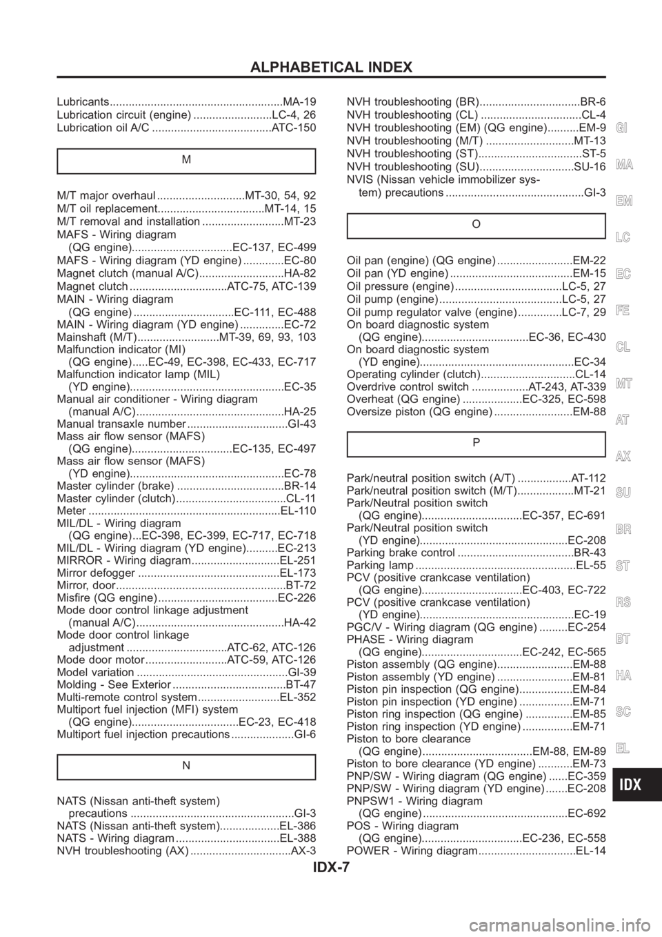
Lubricants<0011001100110011001100110011001100110011001100110011001100110011001100110011001100110011001100110011001100110011001100110011001100110011001100110011001100110011001100110011001100110011001100110011001100
1100110011[..MA-19
Lubrication circuit (engine) .........................LC-4, 26
Lubrication oil A/C ......................................ATC-150
M
M/T major overhaul ............................MT-30, 54, 92
M/T oil replacement..................................MT-14, 15
M/T removal and installation ..........................MT-23
MAFS - Wiring diagram
(QG engine)................................EC-137, EC-499
MAFS - Wiring diagram (YD engine) .............EC-80
Magnet clutch (manual A/C)...........................HA-82
Magnet clutch ...............................ATC-75, ATC-139
MAIN - Wiring diagram
(QG engine) ................................EC-111, EC-488
MAIN - Wiring diagram (YD engine) ..............EC-72
Mainshaft (M/T)..........................MT-39, 69, 93, 103
Malfunction indicator (MI)
(QG engine) .....EC-49, EC-398, EC-433, EC-717
Malfunction indicator lamp (MIL)
(YD engine).................................................EC-35
Manual air conditioner - Wiring diagram
(manual A/C) ...............................................HA-25
Manual transaxle number ................................GI-43
Mass air flow sensor (MAFS)
(QG engine)................................EC-135, EC-497
Mass air flow sensor (MAFS)
(YD engine).................................................EC-78
Master cylinder (brake) ..................................BR-14
Master cylinder (clutch) ...................................CL-11
Meter <0011001100110011001100110011001100110011001100110011001100110011001100110011001100110011001100110011001100110011001100110011001100110011001100110011001100110011001100110011001100110011001100110011001100
110011001100110011001100110011[...EL-110
MIL/DL - Wiring diagram
(QG engine) ...EC-398, EC-399, EC-717, EC-718
MIL/DL - Wiring diagram (YD engine)..........EC-213
MIRROR - Wiring diagram............................EL-251
Mirror defogger .............................................EL-173
Mirror, door<0011001100110011001100110011001100110011001100110011001100110011001100110011001100110011001100110011001100110011001100110011001100110011001100110011001100110011001100110011001100110011001100110011001100
110011[..BT-72
Misfire (QG engine) ......................................EC-226
Mode door control linkage adjustment
(manual A/C) ...............................................HA-42
Mode door control linkage
adjustment ................................ATC-62, ATC-126
Mode door motor ..........................ATC-59, ATC-126
Model variation ................................................GI-39
Molding - See Exterior ....................................BT-47
Multi-remote control system..........................EL-352
Multiport fuel injection (MFI) system
(QG engine)..................................EC-23, EC-418
Multiport fuel injection precautions ....................GI-6
N
NATS (Nissan anti-theft system)
precautions <0011001100110011001100110011001100110011001100110011001100110011001100110011001100110011001100110011001100110011001100110011001100110011001100110011001100110011001100110011001100110011001100110011001100
110011[GI-3
NATS (Nissan anti-theft system)...................EL-386
NATS - Wiring diagram .................................EL-388
NVH troubleshooting (AX) ................................AX-3NVH troubleshooting (BR)................................BR-6
NVH troubleshooting (CL) ................................CL-4
NVH troubleshooting (EM) (QG engine)..........EM-9
NVH troubleshooting (M/T) ............................MT-13
NVH troubleshooting (ST).................................ST-5
NVH troubleshooting (SU)..............................SU-16
NVIS (Nissan vehicle immobilizer sys-
tem) precautions ............................................GI-3
O
Oil pan (engine) (QG engine) ........................EM-22
Oil pan (YD engine) .......................................EM-15
Oil pressure (engine) ..................................LC-5, 27
Oil pump (engine) .......................................LC-5, 27
Oil pump regulator valve (engine) ..............LC-7, 29
On board diagnostic system
(QG engine)..................................EC-36, EC-430
On board diagnostic system
(YD engine).................................................EC-34
Operating cylinder (clutch)..............................CL-14
Overdrive control switch ..................AT-243, AT-339
Overheat (QG engine) ...................EC-325, EC-598
Oversize piston (QG engine) .........................EM-88
P
Park/neutral position switch (A/T) .................AT-112
Park/neutral position switch (M/T)..................MT-21
Park/Neutral position switch
(QG engine)................................EC-357, EC-691
Park/Neutral position switch
(YD engine)...............................................EC-208
Parking brake control .....................................BR-43
Parking lamp <0011001100110011001100110011001100110011001100110011001100110011001100110011001100110011001100110011001100110011001100110011001100110011001100110011001100110011001100110011001100110011001100110011001100
110028[L-55
PCV (positive crankcase ventilation)
(QG engine)................................EC-403, EC-722
PCV (positive crankcase ventilation)
(YD engine).................................................EC-19
PGC/V - Wiring diagram (QG engine) .........EC-254
PHASE - Wiring diagram
(QG engine)................................EC-242, EC-565
Piston assembly (QG engine)........................EM-88
Piston assembly (YD engine) ........................EM-81
Piston pin inspection (QG engine).................EM-84
Piston pin inspection (YD engine) .................EM-71
Piston ring inspection (QG engine) ...............EM-85
Piston ring inspection (YD engine) ................EM-71
Piston to bore clearance
(QG engine) ...................................EM-88, EM-89
Piston to bore clearance (YD engine) ...........EM-73
PNP/SW - Wiring diagram (QG engine) ......EC-359
PNP/SW - Wiring diagram (YD engine) .......EC-208
PNPSW1 - Wiring diagram
(QG engine) ..............................................EC-692
POS - Wiring diagram
(QG engine)................................EC-236, EC-558
POWER - Wiring diagram...............................EL-14
GI
MA
EM
LC
EC
FE
CL
MT
AT
AX
SU
BR
ST
RS
BT
HA
SC
EL
ALPHABETICAL INDEX
IDX-7