Page 2781 of 3189
YEL777D
GI
MA
EM
LC
EC
FE
CL
MT
AT
AX
SU
BR
ST
RS
BT
HA
SC
IDX
NAVIGATION SYSTEM
Wiring Diagram — NAVI — (Cont’d)
EL-445
Page 2782 of 3189
YEL778D
NAVIGATION SYSTEM
Wiring Diagram — NAVI — (Cont’d)
EL-446
Page 2783 of 3189
YEL779D
GI
MA
EM
LC
EC
FE
CL
MT
AT
AX
SU
BR
ST
RS
BT
HA
SC
IDX
NAVIGATION SYSTEM
Wiring Diagram — NAVI — (Cont’d)
EL-447
Page 2784 of 3189
Wiring Diagram — COMM —NJEL0598MODELS WITH LCD DISPLAYNJEL0598S02
YEL738D
NAVIGATION SYSTEM
Wiring Diagram — COMM —
EL-448
Page 2785 of 3189
YEL739D
GI
MA
EM
LC
EC
FE
CL
MT
AT
AX
SU
BR
ST
RS
BT
HA
SC
IDX
NAVIGATION SYSTEM
Wiring Diagram — COMM — (Cont’d)
EL-449
Page 2796 of 3189

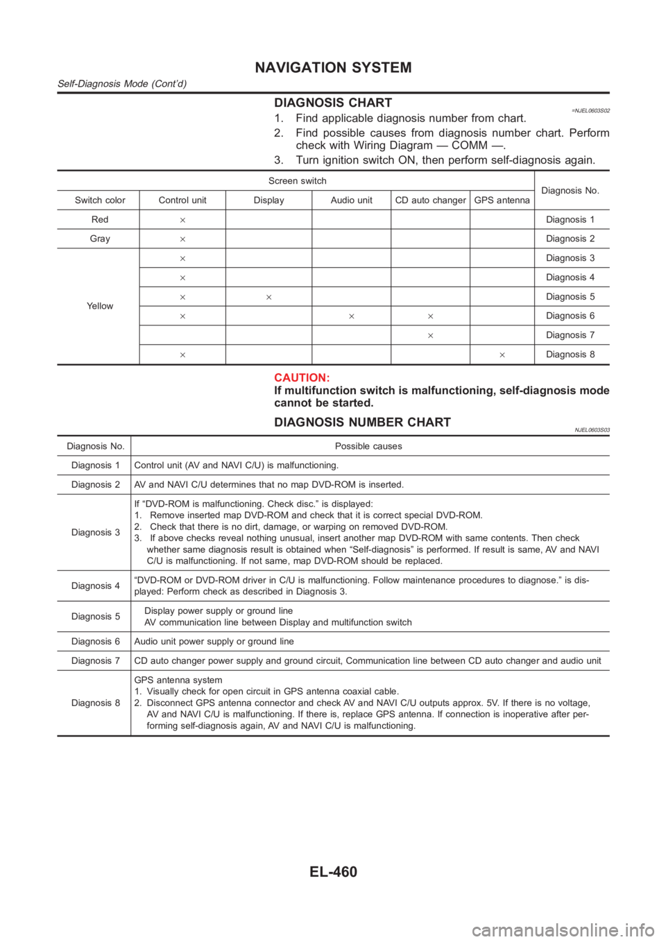
DIAGNOSIS CHART=NJEL0603S021. Find applicable diagnosis number from chart.
2. Find possible causes from diagnosis number chart. Perform
check with Wiring Diagram — COMM —.
3. Turn ignition switch ON, then perform self-diagnosis again.
Screen switch
Diagnosis No.
Switch color Control unit Display Audio unit CD auto changer GPS antenna
Red×Diagnosis 1
Gray×Diagnosis 2
Yellow×Diagnosis 3
×Diagnosis 4
××Diagnosis 5
×××Diagnosis 6
×Diagnosis 7
××Diagnosis 8
CAUTION:
If multifunction switch is malfunctioning, self-diagnosis mode
cannot be started.
DIAGNOSIS NUMBER CHARTNJEL0603S03
Diagnosis No. Possible causes
Diagnosis 1 Control unit (AV and NAVI C/U) is malfunctioning.
Diagnosis 2 AV and NAVI C/U determines that no map DVD-ROM is inserted.
Diagnosis 3If “DVD-ROM is malfunctioning. Check disc.” is displayed:
1. Remove inserted map DVD-ROM and check that it is correct special DVD-ROM.
2. Check that there is no dirt, damage, or warping on removed DVD-ROM.
3. If above checks reveal nothing unusual, insert another map DVD-ROM withsame contents. Then check
whether same diagnosis result is obtained when “Self-diagnosis” is performed. If result is same, AV and NAVI
C/U is malfunctioning. If not same, map DVD-ROM should be replaced.
Diagnosis 4“DVD-ROM or DVD-ROM driver in C/U is malfunctioning. Follow maintenance procedures to diagnose.” is dis-
played: Perform check as described in Diagnosis 3.
Diagnosis 5Display power supply or ground line
AV communication line between Display and multifunction switch
Diagnosis 6 Audio unit power supply or ground line
Diagnosis 7 CD auto changer power supply and ground circuit, Communication line between CD auto changer and audio unit
Diagnosis 8GPS antenna system
1. Visually check for open circuit in GPS antenna coaxial cable.
2. Disconnect GPS antenna connector and check AV and NAVI C/U outputs approx. 5V. If there is no voltage,
AV and NAVI C/U is malfunctioning. If there is, replace GPS antenna. If connection is inoperative after per-
forming self-diagnosis again, AV and NAVI C/U is malfunctioning.
NAVIGATION SYSTEM
Self-Diagnosis Mode (Cont’d)
EL-460
Page 2846 of 3189
TYPE 1=NJEL0536S01System DiagramNJEL0536S0101
SEL825Y
Input/Output Signal ChartNJEL0536S0102T: Transmit R: Receive
Signals ECM TCMSmart entrance
control unitCombination meter
Engine speed signal T R
Brake switch signal R T
Rear window defogger signal R T
Heater fan switch signal R T
Air conditioner switch signal R T
MI signal T R
Current gear position signal T R
Engine coolant temperature signal T R
Fuel consumption signal T R
Vehicle speed signal R T
Seat belt reminder signalRT
Headlamp switch signalTR
Flashing indicator signalTR
Engine cooling fan speed signal T R
Child lock indicator signalTR
Door switches state signal T R
A/C compressor signal T R
Accelerator pedal position signal T R
Output shaft revolution signal R T
OD OFF switch signal R T
OD OFF indicator signal T R
A/T self-diagnosis signal R T
CAN COMMUNICATION
CAN Communication Unit (Cont’d)
EL-510
Page 2847 of 3189
TYPE 2=NJEL0536S02System DiagramNJEL0536S0201
SEL826Y
Input/Output Signal ChartNJEL0536S0202T: Transmit R: Receive
Signals ECMSmart entrance control
unitCombination meter
Engine speed signal T R
Rear window defogger signal R T
Heater fan switch signal R T
Air conditioner switch signal R T
MI signal T R
Engine coolant temperature signal T R
Fuel consumption signal T R
Vehicle speed signal R T
Seat belt reminder signal R T
Headlamp switch signal T R
Flashing indicator signal T R
Engine cooling fan speed signal T R
Child lock indicator signal T R
Door switches state signal T R
A/C compressor signal T R
GI
MA
EM
LC
EC
FE
CL
MT
AT
AX
SU
BR
ST
RS
BT
HA
SC
IDX
CAN COMMUNICATION
CAN Communication Unit (Cont’d)
EL-511