Page 1115 of 3189

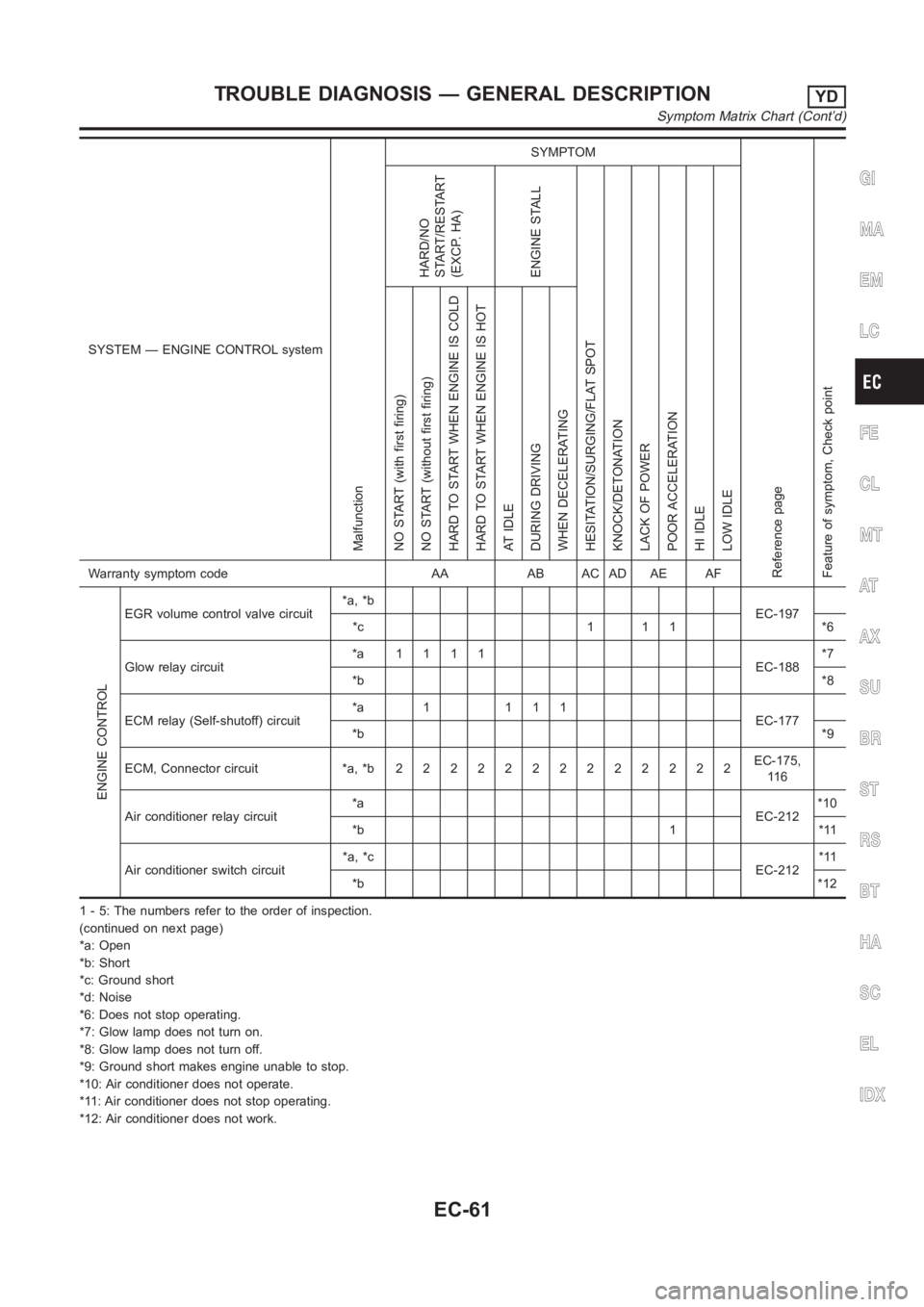
SYSTEM — ENGINE CONTROL system
Malfunction
SYMPTOM
Reference page
Feature of symptom, Check pointHARD/NO
START/RESTART
(EXCP. HA)
ENGINE STALL
HESITATION/SURGING/FLAT SPOT
KNOCK/DETONATION
LACK OF POWER
POOR ACCELERATION
HI IDLE
LOW IDLE NO START (with first firing)
NO START (without first firing)
HARD TO START WHEN ENGINE IS COLD
HARD TO START WHEN ENGINE IS HOT
AT IDLE
DURING DRIVING
WHEN DECELERATINGWarranty symptom code AA AB AC AD AE AF
ENGINE CONTROL
EGR volume control valve circuit*a, *b
EC-197
*c 1 1 1 *6
Glow relay circuit*a 1111
EC-188*7
*b*8
ECM relay (Self-shutoff) circuit*a 1 111
EC-177
*b*9
ECM, Connector circuit *a, *b 2 2 22222222222EC-175,
11 6
Air conditioner relay circuit*a
EC-212*10
*b 1 *11
Air conditioner switch circuit*a, *c
EC-212*11
*b*12
1 - 5: The numbers refer to the order of inspection.
(continued on next page)
*a: Open
*b: Short
*c: Ground short
*d: Noise
*6: Does not stop operating.
*7: Glow lamp does not turn on.
*8: Glow lamp does not turn off.
*9: Ground short makes engine unable to stop.
*10: Air conditioner does not operate.
*11: Air conditioner does not stop operating.
*12: Air conditioner does not work.
GI
MA
EM
LC
FE
CL
MT
AT
AX
SU
BR
ST
RS
BT
HA
SC
EL
IDX
TROUBLE DIAGNOSIS — GENERAL DESCRIPTIONYD
Symptom Matrix Chart (Cont’d)
EC-61
Page 1116 of 3189

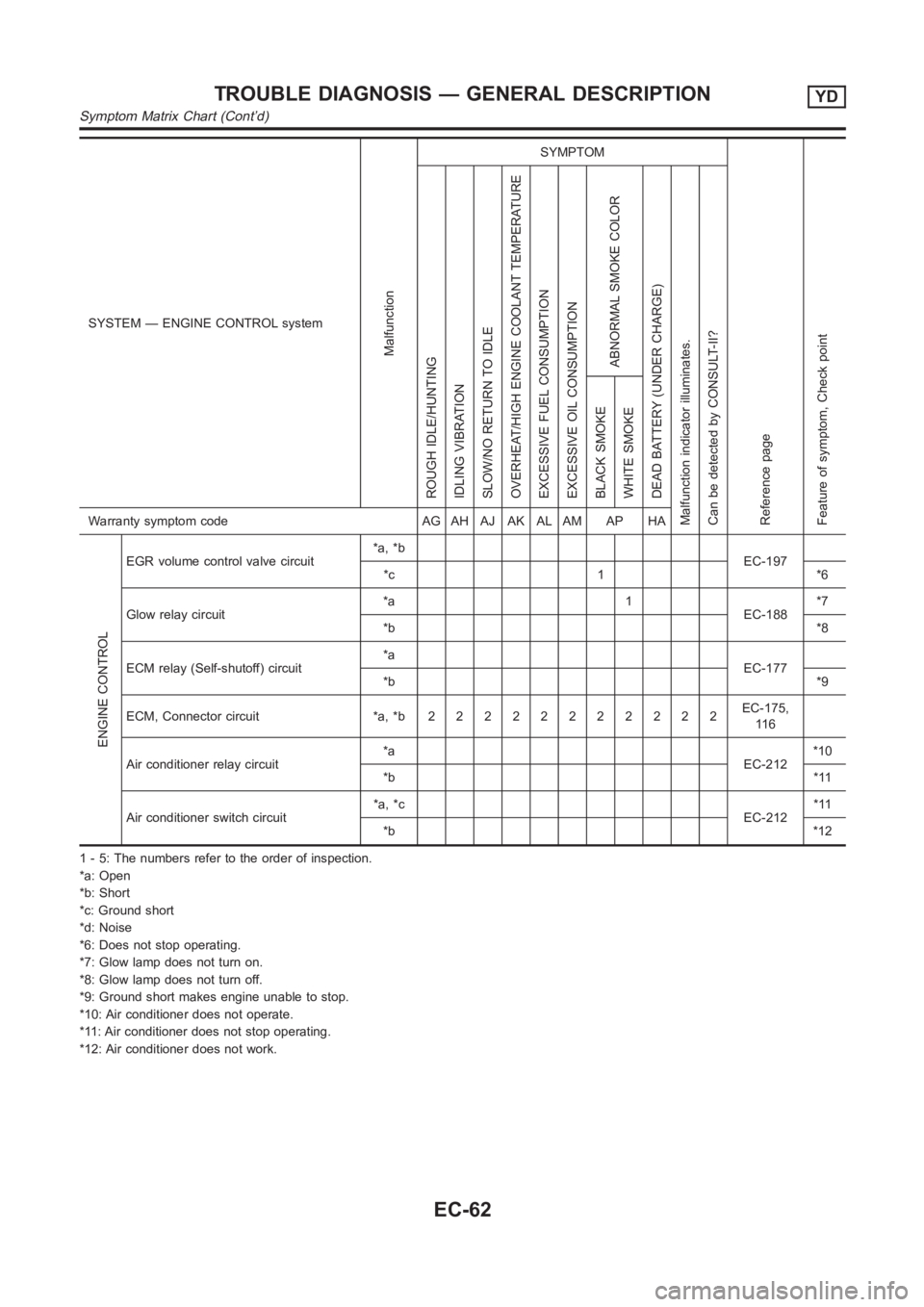
SYSTEM — ENGINE CONTROL system
Malfunction
SYMPTOM
Reference page
Feature of symptom, Check pointROUGH IDLE/HUNTING
IDLING VIBRATION
SLOW/NO RETURN TO IDLE
OVERHEAT/HIGH ENGINE COOLANT TEMPERATURE
EXCESSIVE FUEL CONSUMPTION
EXCESSIVE OIL CONSUMPTION
ABNORMAL SMOKE COLOR
DEAD BATTERY (UNDER CHARGE)
Malfunction indicator illuminates.
Can be detected by CONSULT-II?BLACK SMOKE
WHITE SMOKEWarranty symptom code AG AH AJ AK AL AM AP HA
ENGINE CONTROL
EGR volume control valve circuit*a, *b
EC-197
*c 1 *6
Glow relay circuit*a 1
EC-188*7
*b*8
ECM relay (Self-shutoff) circuit*a
EC-177
*b*9
ECM, Connector circuit *a, *b22222222222EC-175,
11 6
Air conditioner relay circuit*a
EC-212*10
*b*11
Air conditioner switch circuit*a, *c
EC-212*11
*b*12
1 - 5: The numbers refer to the order of inspection.
*a: Open
*b: Short
*c: Ground short
*d: Noise
*6: Does not stop operating.
*7: Glow lamp does not turn on.
*8: Glow lamp does not turn off.
*9: Ground short makes engine unable to stop.
*10: Air conditioner does not operate.
*11: Air conditioner does not stop operating.
*12: Air conditioner does not work.
TROUBLE DIAGNOSIS — GENERAL DESCRIPTIONYD
Symptom Matrix Chart (Cont’d)
EC-62
Page 1117 of 3189

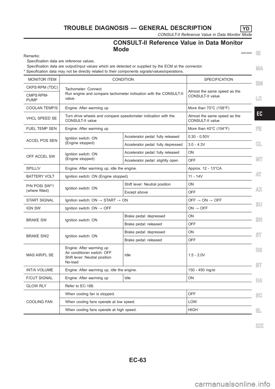
CONSULT-II Reference Value in Data Monitor
Mode
NJEC0634Remarks:
Specification data are reference values.
Specification data are output/input values which are detected or supplied by the ECM at the connector.
* Specification data may not be directly related to their components signals/values/operations.
MONITOR ITEM CONDITION SPECIFICATION
CKPS·RPM (TDC)
Tachometer: Connect
Run engine and compare tachometer indication with the CONSULT-II
value.Almost the same speed as the
CONSULT-II value. CMPS·RPM-
PUMP
COOLAN TEMP/S Engine: After warming up More than 70°C (158°F)
VHCL SPEED SETurn drive wheels and compare speedometer indication with the
CONSULT-II valueAlmost the same speed as the
CONSULT-II value
FUEL TEMP SEN Engine: After warming up More than 40°C (104°F)
ACCEL POS SENIgnition switch: ON
(Engine stopped)Accelerator pedal: fully released 0.30 - 0.50V
Accelerator pedal: fully depressed 3.0 - 4.3V
OFF ACCEL SWIgnition switch: ON
(Engine stopped)Accelerator pedal: fully released ON
Accelerator pedal: slightly open OFF
SPILL/V Engine: After warming up, idle the engine. Approx. 12 - 13°CA
BATTERY VOLT Ignition switch: ON (Engine stopped) 11 - 14V
P/N POSI SW*1
(where fitted)Ignition switch: ONShift lever: Neutral position ON
Except above OFF
START SIGNAL Ignition switch: ON,START,ON OFF,ON,OFF
IGN SW Ignition switch: ON,OFF ON,OFF
BRAKE SW Ignition switch: ONBrake pedal: depressed ON
Brake pedal: released OFF
BRAKE SW2 Ignition switch: ONBrake pedal: depressed ON
Brake pedal: released OFF
MAS AIR/FL SEEngine: After warming up
Air conditioner switch: OFF
Shift lever: Neutral position
No-loadIdle 1.5 - 2.0V
INT/A VOLUME Engine: After warming up, idle the engine. 150 - 450 mg/st
F/CUT SIGNAL Engine: After warming up Idle ON
GLOW RLY Refer to EC-188.
COOLING FANWhen cooling fan is stopped. OFF
When cooling fans operate at low speed. LOW
When cooling fans operate at high speed. HIGH
GI
MA
EM
LC
FE
CL
MT
AT
AX
SU
BR
ST
RS
BT
HA
SC
EL
IDX
TROUBLE DIAGNOSIS — GENERAL DESCRIPTIONYD
CONSULT-II Reference Value in Data Monitor Mode
EC-63
Page 1120 of 3189

SEF289H
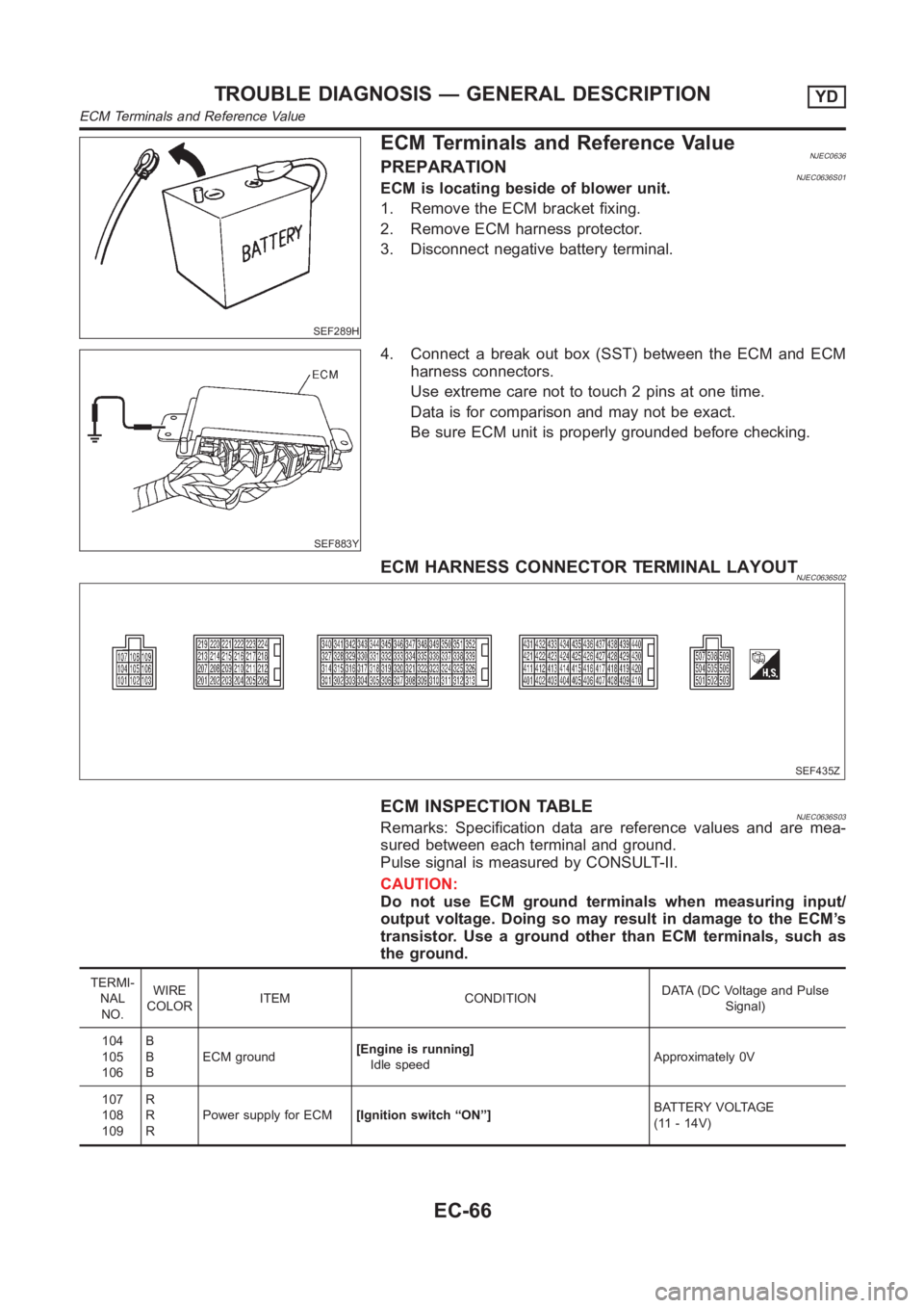
ECM Terminals and Reference ValueNJEC0636PREPARATIONNJEC0636S01ECM is locating beside of blower unit.
1. Remove the ECM bracket fixing.
2. Remove ECM harness protector.
3. Disconnect negative battery terminal.
SEF883Y
4. Connect a break out box (SST) between the ECM and ECM
harness connectors.
Use extreme care not to touch 2 pins at one time.
Data is for comparison and may not be exact.
Be sure ECM unit is properly grounded before checking.
ECM HARNESS CONNECTOR TERMINAL LAYOUTNJEC0636S02
SEF435Z
ECM INSPECTION TABLENJEC0636S03Remarks: Specification data are reference values and are mea-
sured between each terminal and ground.
Pulse signal is measured by CONSULT-II.
CAUTION:
Do not use ECM ground terminals when measuring input/
output voltage. Doing so may result in damage to the ECM’s
transistor. Use a ground other than ECM terminals, such as
the ground.
TERMI-
NAL
NO.WIRE
COLORITEM CONDITIONDATA (DC Voltage and Pulse
Signal)
104
105
106B
B
BECM ground[Engine is running]
Idle speedApproximately 0V
107
108
109R
R
RPower supply for ECM[Ignition switch “ON”]BATTERY VOLTAGE
(11 - 14V)
TROUBLE DIAGNOSIS — GENERAL DESCRIPTIONYD
ECM Terminals and Reference Value
EC-66
Page 1121 of 3189
![NISSAN ALMERA N16 2003 Electronic Repair Manual TERMI-
NAL
NO.WIRE
COLORITEM CONDITIONDATA (DC Voltage and Pulse
Signal)
204 L Air conditioner relay[Engine is running]
Air conditioner switch is “OFF”BATTERY VOLTAGE
(11 - 14V)
[Engine is running NISSAN ALMERA N16 2003 Electronic Repair Manual TERMI-
NAL
NO.WIRE
COLORITEM CONDITIONDATA (DC Voltage and Pulse
Signal)
204 L Air conditioner relay[Engine is running]
Air conditioner switch is “OFF”BATTERY VOLTAGE
(11 - 14V)
[Engine is running](/manual-img/5/57350/w960_57350-1120.png)
TERMI-
NAL
NO.WIRE
COLORITEM CONDITIONDATA (DC Voltage and Pulse
Signal)
204 L Air conditioner relay[Engine is running]
Air conditioner switch is “OFF”BATTERY VOLTAGE
(11 - 14V)
[Engine is running]
Both air conditioner switch and blower fan
switch are “ON”
(Compressor is operating)Approximately 0.1V
214 W/B Glow relay Refer to “Glow Control System”, EC-188.
218 B Sensors’ ground[Engine is running]
Warm-up condition
Idle speedApproximately 0V
219 LG/R Cooling fan relay (Low)[Engine is running]
Cooling fan is not operatingBATTERY VOLTAGE
(11 - 14V)
[Engine is running]
Cooling fan is operatingApproximately 0.1V
221 LG/B Cooling fan relay (High)[Engine is running]
Cooling fan is not operating
Cooling fan is operating at low speedBATTERY VOLTAGE
(11 - 14V)
[Engine is running]
Cooling fan is operating at high speedApproximately 0.1V
223 WMass air flow sensor
power supply[Ignition switch “ON”]Approximately 5V
224 R Mass air flow sensor[Engine is running]
Warm-up condition
Idle speed1.5 - 2.0V
313 L/WElectronic control fuel
injection pump[Engine is running]
Warm-up condition
Idle speedApproximately 0.1V
314 L/RElectronic control fuel
injection pump[Engine is running]
Warm-up condition
Idle speedApproximately 0.4V
316 PUElectronic control fuel
injection pump[Engine is running]
Warm-up condition
Idle speedApproximately 2.5V
317 PElectronic control fuel
injection pump[Engine is running]
Warm-up condition
Idle speedApproximately 2.5V
325 G ECM relay (Self-shutoff)[Ignition switch “ON”]
[Ignition switch “OFF”]
For a few seconds after turning ignition switch
“OFF”Approximately 0.25V
[Ignition switch “OFF”]
A few seconds passed after turning ignition
switch “OFF”BATTERY VOLTAGE
(11 - 14V)
331 ORCrankshaft position sen-
sor (TDC) ground[Engine is running]
Warm-up condition
Idle speedApproximately 0V
334 B/REngine coolant tempera-
ture sensor ground[Ignition switch “ON”]Approximately 0V
GI
MA
EM
LC
FE
CL
MT
AT
AX
SU
BR
ST
RS
BT
HA
SC
EL
IDX
TROUBLE DIAGNOSIS — GENERAL DESCRIPTIONYD
ECM Terminals and Reference Value (Cont’d)
EC-67
Page 1122 of 3189
![NISSAN ALMERA N16 2003 Electronic Repair Manual TERMI-
NAL
NO.WIRE
COLORITEM CONDITIONDATA (DC Voltage and Pulse
Signal)
337
338
350
351W/L
PU/W
GY
OR/BEGR volume control
valve[Engine is running]
Warm-up condition
Idle speed0.1 - 14V
(Voltage signa NISSAN ALMERA N16 2003 Electronic Repair Manual TERMI-
NAL
NO.WIRE
COLORITEM CONDITIONDATA (DC Voltage and Pulse
Signal)
337
338
350
351W/L
PU/W
GY
OR/BEGR volume control
valve[Engine is running]
Warm-up condition
Idle speed0.1 - 14V
(Voltage signa](/manual-img/5/57350/w960_57350-1121.png)
TERMI-
NAL
NO.WIRE
COLORITEM CONDITIONDATA (DC Voltage and Pulse
Signal)
337
338
350
351W/L
PU/W
GY
OR/BEGR volume control
valve[Engine is running]
Warm-up condition
Idle speed0.1 - 14V
(Voltage signals of each ECM
terminals differ according to the
control position of EGR volume
control valve.)
344 WCrankshaft position sen-
sor (TDC)[Engine is running]
Warm-up condition
Idle speedApproximately 0V
SEF333Y
[Engine is running]
Warm-up condition
Engine speed is 2,000 rpmApproximately 0V
SEF334Y
347 L/BEngine coolant tempera-
ture sensor[Engine is running]Approximately 0 - 4.8V
Output voltage varies with
engine coolant temperature
403 R/L Air conditioner switch[Engine is running]
Air conditioner switch is “OFF”BATTERY VOLTAGE
(11 - 14V)
[Engine is running]
Both air conditioner switch and blower fan
switch are “ON”
(Compressor is operating)Approximately 0.1V
405 R/G Stop lamp switch[Ignition switch “ON”]
Brake pedal fully releasedApproximately 0V
[Ignition switch “ON”]
Brake pedal depressedBATTERY VOLTAGE
(11 - 14V)
416 Y/BBrake pedal position
switch[Ignition switch “ON”]
Brake pedal fully releasedBATTERY VOLTAGE
(11 - 14V)
[Ignition switch “ON”]
Brake pedal depressedApproximately 0V
TROUBLE DIAGNOSIS — GENERAL DESCRIPTIONYD
ECM Terminals and Reference Value (Cont’d)
EC-68
Page 1123 of 3189
![NISSAN ALMERA N16 2003 Electronic Repair Manual TERMI-
NAL
NO.WIRE
COLORITEM CONDITIONDATA (DC Voltage and Pulse
Signal)
417 PU/R Vehicle speed sensor[Engine is running]
Lift up the vehicle
In 1st gear position
Vehicle speed is 10 km/h (6 MPH)0 - A NISSAN ALMERA N16 2003 Electronic Repair Manual TERMI-
NAL
NO.WIRE
COLORITEM CONDITIONDATA (DC Voltage and Pulse
Signal)
417 PU/R Vehicle speed sensor[Engine is running]
Lift up the vehicle
In 1st gear position
Vehicle speed is 10 km/h (6 MPH)0 - A](/manual-img/5/57350/w960_57350-1122.png)
TERMI-
NAL
NO.WIRE
COLORITEM CONDITIONDATA (DC Voltage and Pulse
Signal)
417 PU/R Vehicle speed sensor[Engine is running]
Lift up the vehicle
In 1st gear position
Vehicle speed is 10 km/h (6 MPH)0 - Approximately 8V
SEF891Y
[Engine is running]
Lift up the vehicle
In 2nd gear position
Vehicle speed is 30 km/h (19 MPH)Approximately 6V
SEF892Y
418 G/ORPark/Neutral position
switch (where fitted)[Ignition switch “ON”]
Gear position is “Neutral”Approximately 0V
[Ignition switch “ON”]
Except the above gear positionBATTERY VOLTAGE
(11 - 14V)
422 B/Y Start signal[Ignition switch “ON”]Approximately 0V
[Ignition switch “START”]BATTERY VOLTAGE
(11 - 14V)
425 P/BAccelerator position sen-
sor ground[Engine is running]
Warm-up condition
Idle speedApproximately 0V
426 BR/RAccelerator position
switch (Idle) ground[Ignition switch “ON”]Approximately 0V
433 G/YAccelerator position sen-
sor power supply[Ignition switch “ON”]Approximately 5V
434 WAccelerator position sen-
sor[Ignition switch “ON”]
Accelerator pedal fully released0.30 - 0.50V
[Ignition switch “ON”]
Accelerator pedal fully depressed3.0 - 4.3V
435 W/GAccelerator position
switch (Idle)[Ignition switch “ON”]
Accelerator pedal fully releasedApproximately 0V
[Ignition switch “ON”]
Accelerator pedal depressedBATTERY VOLTAGE
(11 - 14V)
GI
MA
EM
LC
FE
CL
MT
AT
AX
SU
BR
ST
RS
BT
HA
SC
EL
IDX
TROUBLE DIAGNOSIS — GENERAL DESCRIPTIONYD
ECM Terminals and Reference Value (Cont’d)
EC-69
Page 1124 of 3189
TERMI-
NAL
NO.WIRE
COLORITEM CONDITIONDATA (DC Voltage and Pulse
Signal)
439 L/OR Tachometer[Engine is running]
Warm-up condition
Idle speedApproximately 4.8V
SEF325Y
[Engine is running]
Warm-up condition
Engine speed is 2,000 rpmApproximately 4.6V
SEF326Y
505 OR/L Malfunction indicator[Ignition switch “ON”]Approximately 1V
[Engine is running]
Idle speedBATTERY VOLTAGE
(11 - 14V)
507 W/R Ignition switch[Ignition switch “OFF”]0V
[Ignition switch “ON”]BATTERY VOLTAGE
(11 - 14V)
508 OR Glow lamp[Ignition switch “ON”]
Glow lamp is “ON”Approximately 1V
[Ignition switch “ON”]
Glow lamp is “OFF”BATTERY VOLTAGE
(11 - 14V)
TROUBLE DIAGNOSIS — GENERAL DESCRIPTIONYD
ECM Terminals and Reference Value (Cont’d)
EC-70