Page 1159 of 3189

AEC110
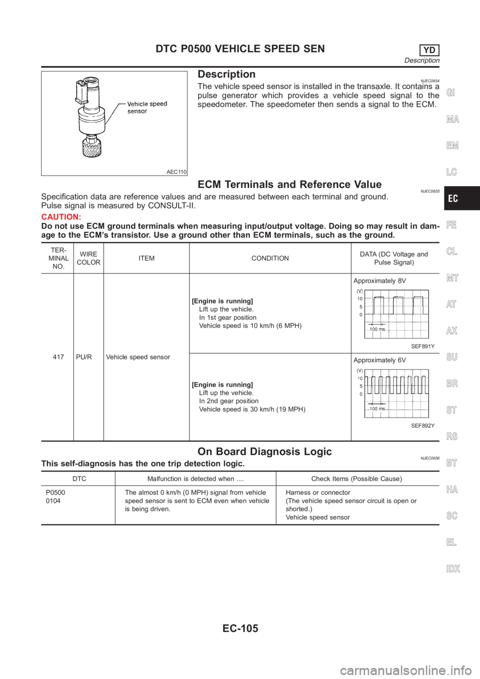
DescriptionNJEC0654The vehicle speed sensor is installed in the transaxle. It contains a
pulse generator which provides a vehicle speed signal to the
speedometer. The speedometer then sends a signal to the ECM.
ECM Terminals and Reference ValueNJEC0655Specification data are reference values and are measured between each terminal and ground.
Pulse signal is measured by CONSULT-II.
CAUTION:
Do not use ECM ground terminals when measuring input/output voltage. Doing so may result in dam-
age to the ECM’s transistor. Use a ground other than ECM terminals, such as the ground.
TER-
MINAL
NO.WIRE
COLORITEM CONDITIONDATA (DC Voltage and
Pulse Signal)
417 PU/R Vehicle speed sensor[Engine is running]
Lift up the vehicle.
In 1st gear position
Vehicle speed is 10 km/h (6 MPH)Approximately 8V
SEF891Y
[Engine is running]
Lift up the vehicle.
In 2nd gear position
Vehicle speed is 30 km/h (19 MPH)Approximately 6V
SEF892Y
On Board Diagnosis LogicNJEC0656This self-diagnosis has the one trip detection logic.
DTC Malfunction is detected when .... Check Items (Possible Cause)
P0500
0104The almost 0 km/h (0 MPH) signal from vehicle
speed sensor is sent to ECM even when vehicle
is being driven.Harness or connector
(The vehicle speed sensor circuit is open or
shorted.)
Vehicle speed sensor
GI
MA
EM
LC
FE
CL
MT
AT
AX
SU
BR
ST
RS
BT
HA
SC
EL
IDX
DTC P0500 VEHICLE SPEED SENYD
Description
EC-105
Page 1160 of 3189
SEF864Y
Overall Function CheckNJEC0657Use this procedure to check the overall function of the vehicle
speed sensor circuit. During this check, a DTC might not be con-
firmed.
WITH CONSULT-IINJEC0657S011) Lift up the vehicle.
2) Start engine.
3) Read vehicle speed sensor signal in “DATA MONITOR” mode
with CONSULT-II.
The vehicle speed on CONSULT-II should be able to
exceed 10 km/h (6 MPH) when rotating wheels with suit-
able gear position.
4) If NG, go to “Diagnostic Procedure”, EC-108.
WITHOUT CONSULT-IINJEC0657S021) Lift up the vehicle.
2) Start engine.
3) Read the voltage signal for the vehicle speed sensor with an
oscilloscope. Refer to “ECM Terminals and Reference Value”,
EC-105.
4) Verify that the oscilloscope screen shows the signal wave as
shown at “ECM Terminals and Reference Value”, EC-105.
5) If NG, go to “Diagnostic Procedure”, EC-108.
DTC P0500 VEHICLE SPEED SENYD
Overall Function Check
EC-106
Page 1162 of 3189

Diagnostic ProcedureNJEC0659
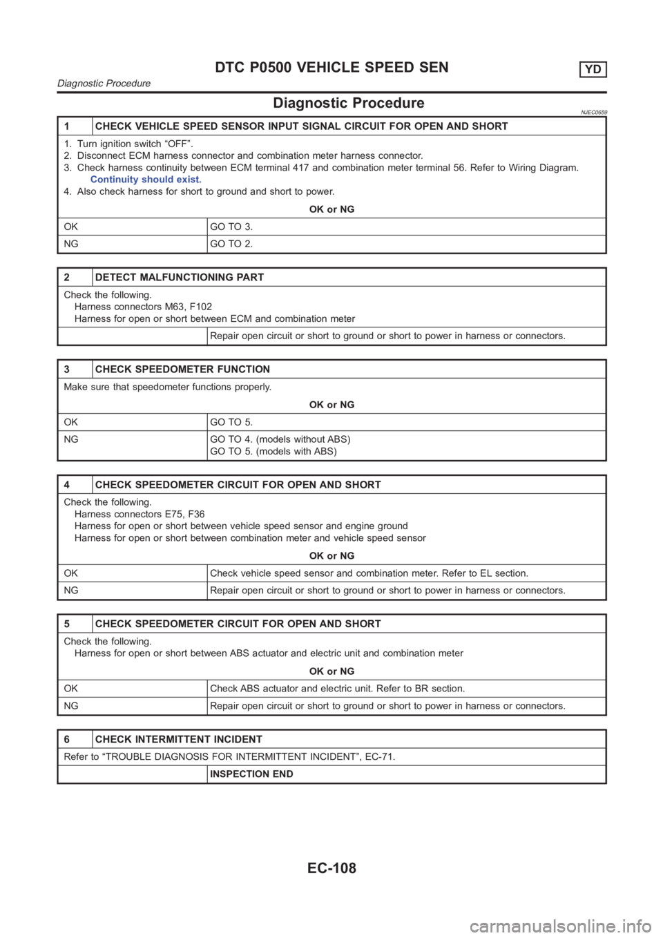
1 CHECK VEHICLE SPEED SENSOR INPUT SIGNAL CIRCUIT FOR OPEN AND SHORT
1. Turn ignition switch “OFF”.
2. Disconnect ECM harness connector and combination meter harness connector.
3. Check harness continuity between ECM terminal 417 and combination meter terminal 56. Refer to Wiring Diagram.
Continuity should exist.
4. Also check harness for short to ground and short to power.
OK or NG
OK GO TO 3.
NG GO TO 2.
2 DETECT MALFUNCTIONING PART
Check the following.
Harness connectors M63, F102
Harness for open or short between ECM and combination meter
Repair open circuit or short to ground or short to power in harness or connectors.
3 CHECK SPEEDOMETER FUNCTION
Make sure that speedometer functions properly.
OK or NG
OK GO TO 5.
NG GO TO 4. (models without ABS)
GO TO 5. (models with ABS)
4 CHECK SPEEDOMETER CIRCUIT FOR OPEN AND SHORT
Check the following.
Harness connectors E75, F36
Harness for open or short between vehicle speed sensor and engine ground
Harness for open or short between combination meter and vehicle speed sensor
OK or NG
OK Check vehicle speed sensor and combination meter. Refer to EL section.
NG Repair open circuit or short to ground or short to power in harness or connectors.
5 CHECK SPEEDOMETER CIRCUIT FOR OPEN AND SHORT
Check the following.
Harness for open or short between ABS actuator and electric unit and combination meter
OK or NG
OK Check ABS actuator and electric unit. Refer to BR section.
NG Repair open circuit or short to ground or short to power in harness or connectors.
6 CHECK INTERMITTENT INCIDENT
Refer to “TROUBLE DIAGNOSIS FOR INTERMITTENT INCIDENT”, EC-71.
INSPECTION END
DTC P0500 VEHICLE SPEED SENYD
Diagnostic Procedure
EC-108
Page 1163 of 3189

SEF893Y
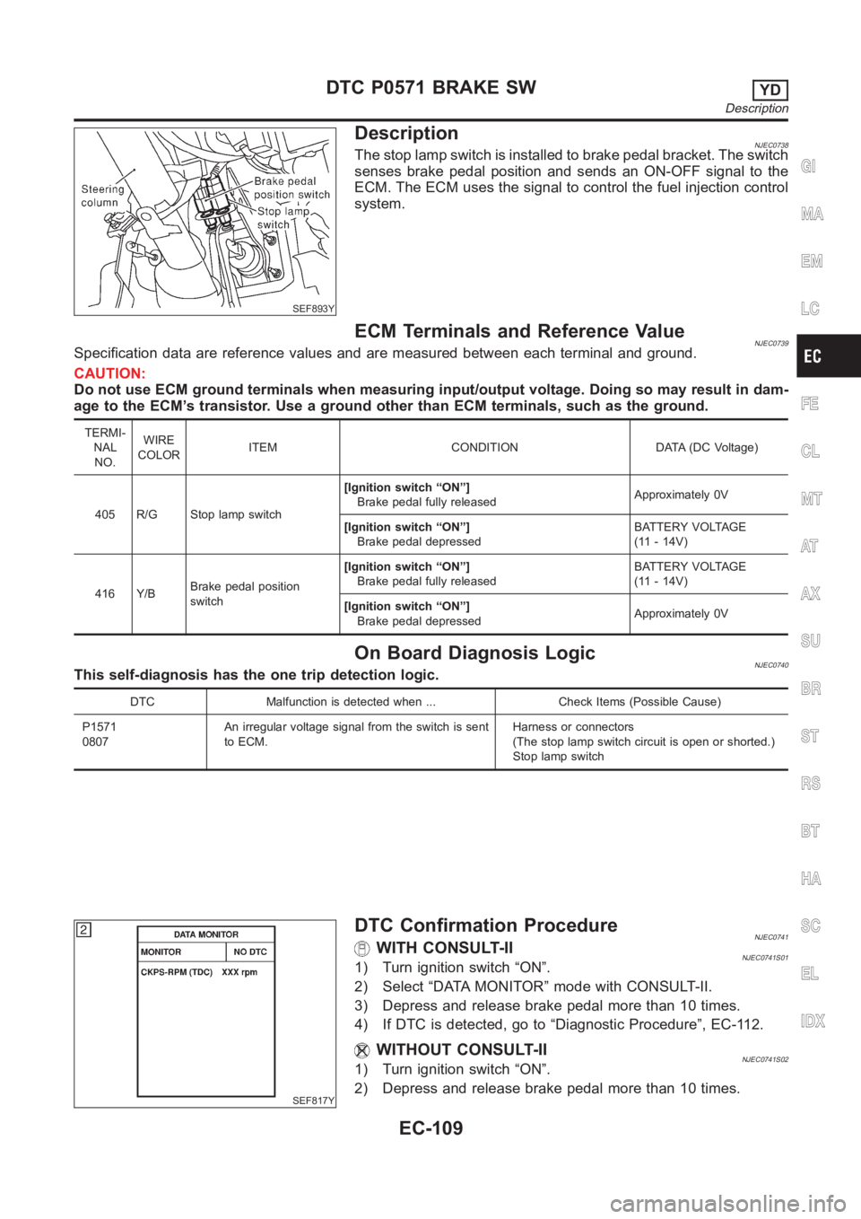
DescriptionNJEC0738The stop lamp switch is installed to brake pedal bracket. The switch
senses brake pedal position and sends an ON-OFF signal to the
ECM. The ECM uses the signal to control the fuel injection control
system.
ECM Terminals and Reference ValueNJEC0739Specification data are reference values and are measured between each terminal and ground.
CAUTION:
Do not use ECM ground terminals when measuring input/output voltage. Doing so may result in dam-
age to the ECM’s transistor. Use a ground other than ECM terminals, such as the ground.
TERMI-
NAL
NO.WIRE
COLORITEM CONDITION DATA (DC Voltage)
405 R/G Stop lamp switch[Ignition switch “ON”]
Brake pedal fully releasedApproximately 0V
[Ignition switch “ON”]
Brake pedal depressedBATTERY VOLTAGE
(11 - 14V)
416 Y/BBrake pedal position
switch[Ignition switch “ON”]
Brake pedal fully releasedBATTERY VOLTAGE
(11 - 14V)
[Ignition switch “ON”]
Brake pedal depressedApproximately 0V
On Board Diagnosis LogicNJEC0740This self-diagnosis has the one trip detection logic.
DTC Malfunction is detected when ... Check Items (Possible Cause)
P1571
0807An irregular voltage signal from the switch is sent
to ECM.Harness or connectors
(The stop lamp switch circuit is open or shorted.)
Stop lamp switch
SEF817Y
DTC Confirmation ProcedureNJEC0741WITH CONSULT-IINJEC0741S011) Turn ignition switch “ON”.
2) Select “DATA MONITOR” mode with CONSULT-II.
3) Depress and release brake pedal more than 10 times.
4) If DTC is detected, go to “Diagnostic Procedure”, EC-112.
WITHOUT CONSULT-IINJEC0741S021) Turn ignition switch “ON”.
2) Depress and release brake pedal more than 10 times.
GI
MA
EM
LC
FE
CL
MT
AT
AX
SU
BR
ST
RS
BT
HA
SC
EL
IDX
DTC P0571 BRAKE SWYD
Description
EC-109
Page 1164 of 3189
3) Turn ignition switch “OFF”, wait at least 5 seconds and then
turn “ON”.
4) Perform “Diagnostic Test Mode II (Self-diagnostic results)” with
ECM.
5) If DTC is detected, go to “Diagnostic Procedure”, EC-112.
DTC P0571 BRAKE SWYD
DTC Confirmation Procedure (Cont’d)
EC-110
Page 1167 of 3189
4 CHECK STOP LAMP SWITCH INPUT SIGNAL CIRCUIT FOR OPEN AND SHORT
1. Turn ignition switch “OFF”.
2. Disconnect ECM harness connector.
3. Disconnect stop lamp switch harness connector.
SEF893Y
4. Check harness continuity between ECM terminal 405 and stop lamp switch terminal 2. Refer to Wiring Diagram.
Continuity should exist.
5. Also check harness for short to ground and short to power.
OK or NG
OK GO TO 6.
NG GO TO 5.
5 DETECT MALFUNCTIONING PART
Check the following.
Harness connectors M74, F112
Harness for open or short between ECM and stop lamp switch
Repair open circuit or short to ground or short to power in harness or connectors.
6 CHECK STOP LAMP SWITCH
Check continuity between stop lamp switch terminals 1 and 2 under the following conditions.
SEF904Y
OK or NG
OK GO TO 7.
NG Replace stop lamp switch.
GI
MA
EM
LC
FE
CL
MT
AT
AX
SU
BR
ST
RS
BT
HA
SC
EL
IDX
DTC P0571 BRAKE SWYD
Diagnostic Procedure (Cont’d)
EC-113
Page 1168 of 3189

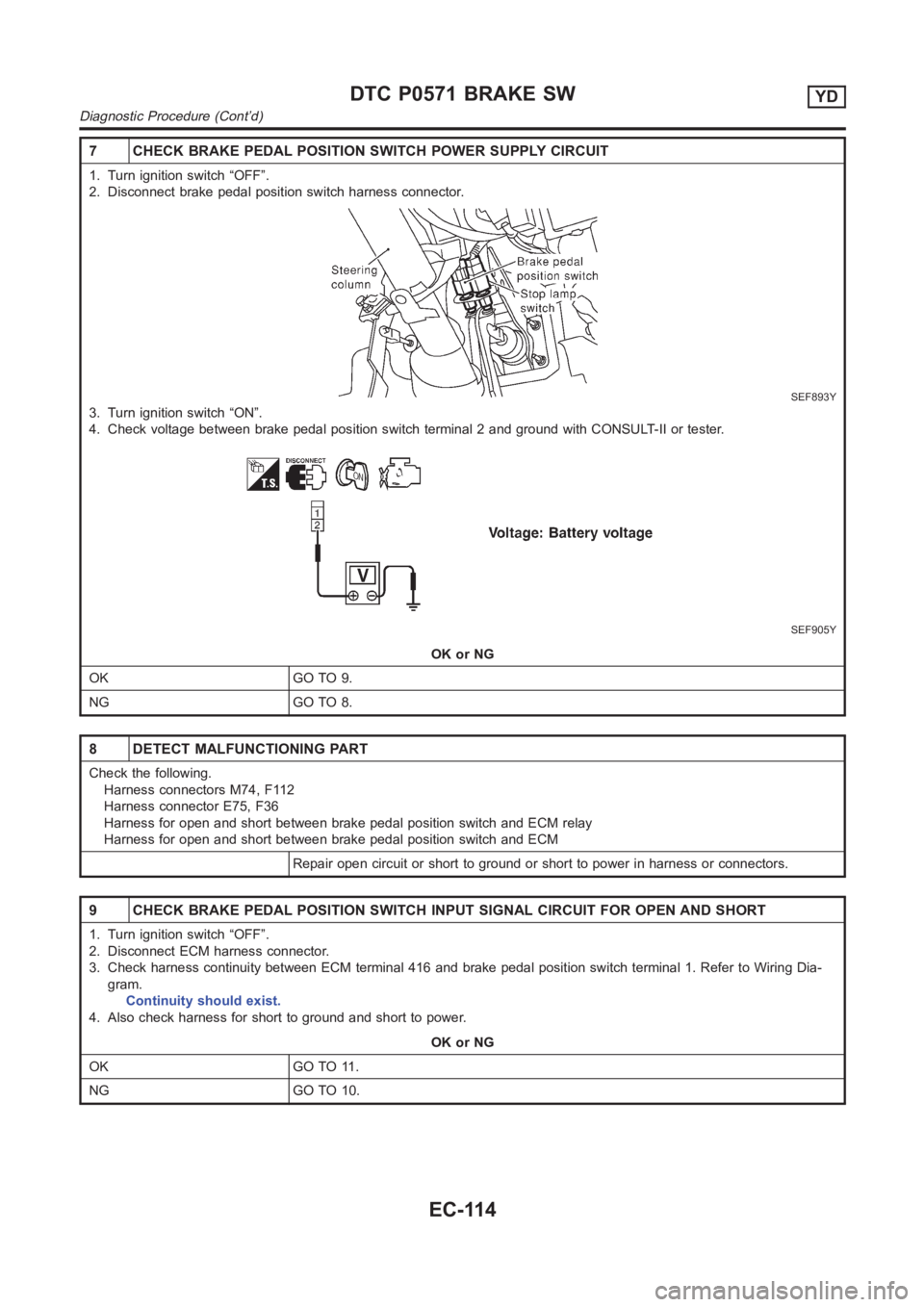
7 CHECK BRAKE PEDAL POSITION SWITCH POWER SUPPLY CIRCUIT
1. Turn ignition switch “OFF”.
2. Disconnect brake pedal position switch harness connector.
SEF893Y
3. Turn ignition switch “ON”.
4. Check voltage between brake pedal position switch terminal 2 and groundwith CONSULT-II or tester.
SEF905Y
OK or NG
OK GO TO 9.
NG GO TO 8.
8 DETECT MALFUNCTIONING PART
Check the following.
Harness connectors M74, F112
Harness connector E75, F36
Harness for open and short between brake pedal position switch and ECM relay
Harness for open and short between brake pedal position switch and ECM
Repair open circuit or short to ground or short to power in harness or connectors.
9 CHECK BRAKE PEDAL POSITION SWITCH INPUT SIGNAL CIRCUIT FOR OPEN AND SHORT
1. Turn ignition switch “OFF”.
2. Disconnect ECM harness connector.
3. Check harness continuity between ECM terminal 416 and brake pedal position switch terminal 1. Refer to Wiring Dia-
gram.
Continuity should exist.
4. Also check harness for short to ground and short to power.
OK or NG
OK GO TO 11.
NG GO TO 10.
DTC P0571 BRAKE SWYD
Diagnostic Procedure (Cont’d)
EC-114
Page 1169 of 3189
10 DETECT MALFUNCTIONING PART
Check the following.
Harness connectors M74, F112
Harness for open or short between ECM and brake pedal position switch
Repair open circuit or short to ground or short to power in harness or connectors.
11 CHECK BRAKE PEDAL POSITION SWITCH
Check continuity between brake pedal position switch terminals 1 and 2 under the following conditions.
SEF906Y
OK or NG
OK GO TO 12.
NG Replace brake pedal position switch.
12 CHECK INTERMITTENT INCIDENT
Refer to “TROUBLE DIAGNOSIS FOR INTERMITTENT INCIDENT”, EC-71.
INSPECTION END
GI
MA
EM
LC
FE
CL
MT
AT
AX
SU
BR
ST
RS
BT
HA
SC
EL
IDX
DTC P0571 BRAKE SWYD
Diagnostic Procedure (Cont’d)
EC-115