2003 NISSAN ALMERA N16 combination switch
[x] Cancel search: combination switchPage 2473 of 3189
from key switch terminal 2
to smart entrance control unit terminal 5.
Ground is supplied
from body grounds B9, B21 and D96 (Hatchback) or B308 (Sedan)
through front door switch (driver side) terminal 3 and 2
to smart entrance control unit terminal 43.
And, then smart entrance control unit receives any door lock signal.
LIGHT WARNING CHIMENJEL0453S02With ignition switch OFF, driver’s door open, and lighting switch in 1ST or2ND position, warning chime will
sound. Power is supplied.
from lighting switch terminal 12
through daytime light control unit terminals 11 and 10 (with daytime lightsystem)
to smart entrance control unit terminal 17
Ground is supplied
from front door switch (driver side) terminal 2
to smart entrance control unit terminal 43.
Front door switch (driver side) terminal 3 is grounded through body grounds B9, B21 and D96 (Hatchback) or
B308 (Sedan).
System Description/YD Engine Models without
Common Rail and K9K Engine Models
NJEL0550The warning chime is controlled by the time control unit.
The warning chime is located in the time control unit.
Power is supplied at all times
through 15A fuse [No. 5, located in fuse block (J/B)]
to time control unit terminal 9.
through 10A fuse [No. 12, located in the fuse block (J/B)]
to key switch terminal 1.
through 10A fuse (No. 38, located in the fuse and fusible link box)
to lighting switch terminal 11.
With the ignition switch in the ON or START position, power is supplied
through 10A fuse [No. 10, located in the fuse block (J/B)]
to time control unit terminal 1.
Ground is supplied to time control unit terminal 16 through body grounds M28 and M67.
When a signal, or combination of signals, is received by the time control unit, the warning chime will sound.
IGNITION KEY WARNING CHIMENJEL0550S01With the key in the ignition switch in the OFF position, the driver’s door open and driver’s door locked, the
warning chime will sound. Power is supplied
from key switch terminal 2
to time control unit terminal 22.
Ground is supplied
from body grounds B9, B21 and D96 (Hatchback) or B308 (Sedan)
through front door switch (driver side) terminal 3 and 2
to time control unit terminal 6, and
Ground is interrupted,
from body grounds M28 and M67
to time control unit terminal 35
LIGHT WARNING CHIMENJEL0550S02With ignition switch OFF, driver’s door open, and lighting switch in 1ST or2ND position, warning chime will
sound. Power is supplied.
from lighting switch terminal 12
to time control unit terminal 10
GI
MA
EM
LC
EC
FE
CL
MT
AT
AX
SU
BR
ST
RS
BT
HA
SC
IDX
WARNING CHIME
System Description/QG Engine Models and YD Engine Models with Common Rail(Cont’d)
EL-137
Page 2494 of 3189
System DescriptionNJEL0456WIPER OPERATIONNJEL0456S01The wiper switch is controlled by a lever built into the combination switch.
There are three wiper switch positions:
LO speed
HI speed
INT (Intermittent)
With the ignition switch in the ON or START position, power is supplied
through 20A fuse [No. 25, located in the fuse block (J/B)]
to front wiper motor terminal 5.
Low and High Speed Wiper OperationNJEL0456S0101Ground is supplied to wiper and washer switch terminal 17 through body grounds E30 and E73.
When the wiper switch is placed in the LO position, ground is supplied
through terminal 14 of the front wiper and washer switch
to front wiper motor terminal 2.
With power and ground supplied, the wiper motor operates at low speed.
When the wiper switch is placed in the HI position, ground is supplied
through terminal 16 of the front wiper and washer switch
to wiper motor terminal 1.
With power and ground supplied, the wiper motor operates at high speed.
Auto Stop OperationNJEL0456S0102With wiper switch turned OFF, wiper motor will continue to operate until wiper arms reach windshield base.
When wiper arms are not located at base of windshield with wiper switch OFF,ground is provided
from terminal 14 of the front wiper and washer switch
to front wiper motor terminal 2, in order to continue wiper motor operationat low speed.
Ground is also supplied
through terminal 13 of the front wiper and washer switch
to front wiper motor terminal 4
through terminal 3 of front wiper motor
through body grounds E30 and E73.
When wiper arms reach base of windshield, front wiper motor terminals 4 and5 are connected instead of ter-
minals 4 and 3. Wiper motor will then stop wiper arms at the STOP position.
Intermittent OperationNJEL0456S0103The front wiper motor operates the wiper arms one time at low speed at a set interval of approximately 1 to
13 seconds. This feature is controlled by the wiper amplifier (INT SW) combined with front wiper switch.
When the wiper switch is placed in the INT position, ground is supplied to wiper amplifier (WIPER SW INT)
and (ACC).
The desired interval time is input to wiper amplifier (INT VR) from wiper volume switch combined with front
wiper and washer switch.
When the wiper switch is placed in the INT position, intermittent ground issupplied
through wiper amplifier (OUTPUT) and
through terminal 14 of front wiper and washer switch
to front wiper motor terminal 5.
The wiper motor operates at low speed at the desired interval.
When the lever is pulled to the WASH position for one second or more, the wiper motor operates at low speed
for approximately 3 seconds to clean windshield. This feature is controlled by the wiper amplifier in the same
manner as the intermittent operation.
WASHER OPERATIONNJEL0456S02With the ignition switch in the ON or START position, power is supplied
through 10A fuse [No. 27, located in the fuse block (J/B)]
through front wiper switch terminals 15 and 18.
to front washer motor terminal 1.
FRONT WIPER AND WASHER
System Description
EL-158
Page 2551 of 3189
System DescriptionNJEL0555MULTIFUNCTION SWITCH SYSTEMNJEL0555S01Refer to Owner′s Manual for multifunction switch operating instruc-
tions.
Using the multifunction switch at the center of the instrument panel,
it can be operating the following systems:
Auto A/C system
Board computer
Audio system
POWER SUPPLY AND GROUNDNJEL0555S02Power is Supplied at All TimesNJEL0555S0201through 15A fuse (No. 40, located in fuse and fusible link box)
to display unit terminal 23
to audio unit terminals 3 and 4.
When Ignition Switch is in ACC or ON Position, Power
is Supplied
NJEL0555S0202through 10A fuse [No. 1, located in fuse block (J/B)]
to display unit terminal 24,
to multifunction switch terminal 6 and
to audio unit terminal 2.
When Ignition Switch is in ON or START Position,
Power is Supplied
NJEL0555S0203through 10A fuse [No. 1, located in fuse block (J/B)]
to display unit terminal 22.
Ground is SuppliedNJEL0555S0204to multifunction switch terminal 1 and
to display unit terminal 21
through body grounds M28, M67 and F118 (Gasoline engine
models).
AV COMMUNICATION LINENJEL0555S03Display unit is communicated by the following unit with communi-
cation line.
Multifunction switch
Audio unit
Auto A/C unit
Combination meter
Display unit received operation signal from multifunction switch,
and it send operation signal to audio unit, auto A/C unit or combi-
nation meter.
BOARD COMPUTERNJEL0555S04Refer to Owner′s Manual for board computer operating instruc-
tions.
Board computer is monitoring to the following five type information.
GI
MA
EM
LC
EC
FE
CL
MT
AT
AX
SU
BR
ST
RS
BT
HA
SC
IDX
VFD DISPLAY
System Description
EL-215
Page 2558 of 3189
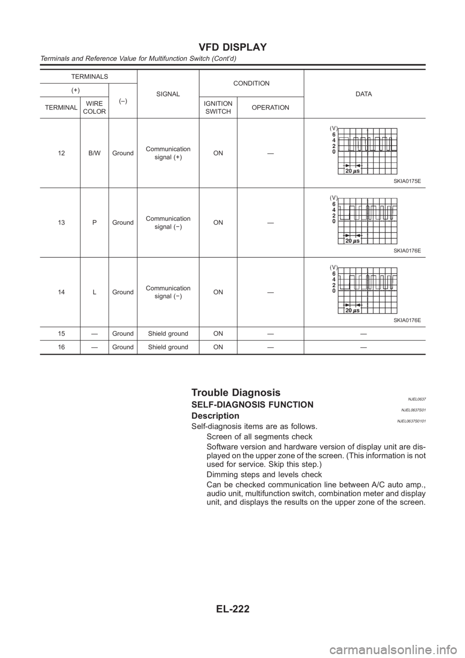
TERMINALS
SIGNALCONDITION
DATA (+)
(–)
TERMINALWIRE
COLORIGNITION
SWITCHOPERATION
12 B/W GroundCommunication
signal (+)ON —
SKIA0175E
13 P GroundCommunication
signal (−)ON —
SKIA0176E
14 L GroundCommunication
signal (−)ON —
SKIA0176E
15 — Ground Shield ground ON — —
16 — Ground Shield ground ON — —
Trouble DiagnosisNJEL0637SELF-DIAGNOSIS FUNCTIONNJEL0637S01DescriptionNJEL0637S0101Self-diagnosis items are as follows.
Screen of all segments check
Software version and hardware version of display unit are dis-
played on the upper zone of the screen. (This information is not
used for service. Skip this step.)
Dimming steps and levels check
Can be checked communication line between A/C auto amp.,
audio unit, multifunction switch, combination meter and display
unit, and displays the results on the upper zone of the screen.
VFD DISPLAY
Terminals and Reference Value for Multifunction Switch (Cont’d)
EL-222
Page 2559 of 3189
YEL828D
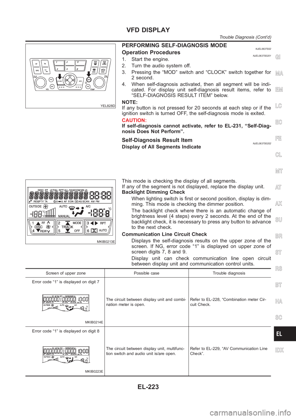
PERFORMING SELF-DIAGNOSIS MODENJEL0637S02Operation ProceduresNJEL0637S02011. Start the engine.
2. Turn the audio system off.
3. Pressing the “MOD” switch and “CLOCK” switch together for
2 second.
4. When self-diagnosis activated, then all segment will be indi-
cated. For display unit self-diagnosis result items, refer to
“SELF-DIAGNOSIS RESULT ITEM” below.
NOTE:
If any button is not pressed for 20 seconds at each step or if the
ignition switch is turned OFF, the self-diagnosis mode is exited.
CAUTION:
If self-diagnosis cannot activate, refer to EL-231, “Self-Diag-
nosis Does Not Perform”.
Self-Diagnosis Result ItemNJEL0637S0202Display of All Segments Indicate
MKIB0213E
This mode is checking the display of all segments.
If any of the segment is not displayed, replace the display unit.
Backlight Dimming Check
When lighting switch is first or second position, display is dim-
ming. This mode is checking the dimmer position.
The backlight check where there is an automatic change of
brightness level (4 steps) every 2 seconds. At the end of the
backlight check, it is necessary to press any button to advance
to the next check.
Communication Line Circuit Check
Displays the self-diagnosis results on the upper zone of the
screen. If NG, error code “1” is displayed on upper zone of
screen digits 7, 8 and 9.
Display unit can check communication line open circuit
between display unit and communication control units.
Screen of upper zone Possible case Trouble diagnosis
Error code “1” is displayed on digit 7
MKIB0214E
The circuit between display unit and combi-
nation meter is open.Refer to EL-228, “Combination meter Cir-
cuit Check.
Error code “1” is displayed on digit 8
MKIB0223E
The circuit between display unit, multifunc-
tion switch and audio unit is/are open.Refer to EL-229, “AV Communication Line
Check”.
GI
MA
EM
LC
EC
FE
CL
MT
AT
AX
SU
BR
ST
RS
BT
HA
SC
IDX
VFD DISPLAY
Trouble Diagnosis (Cont’d)
EL-223
Page 2705 of 3189
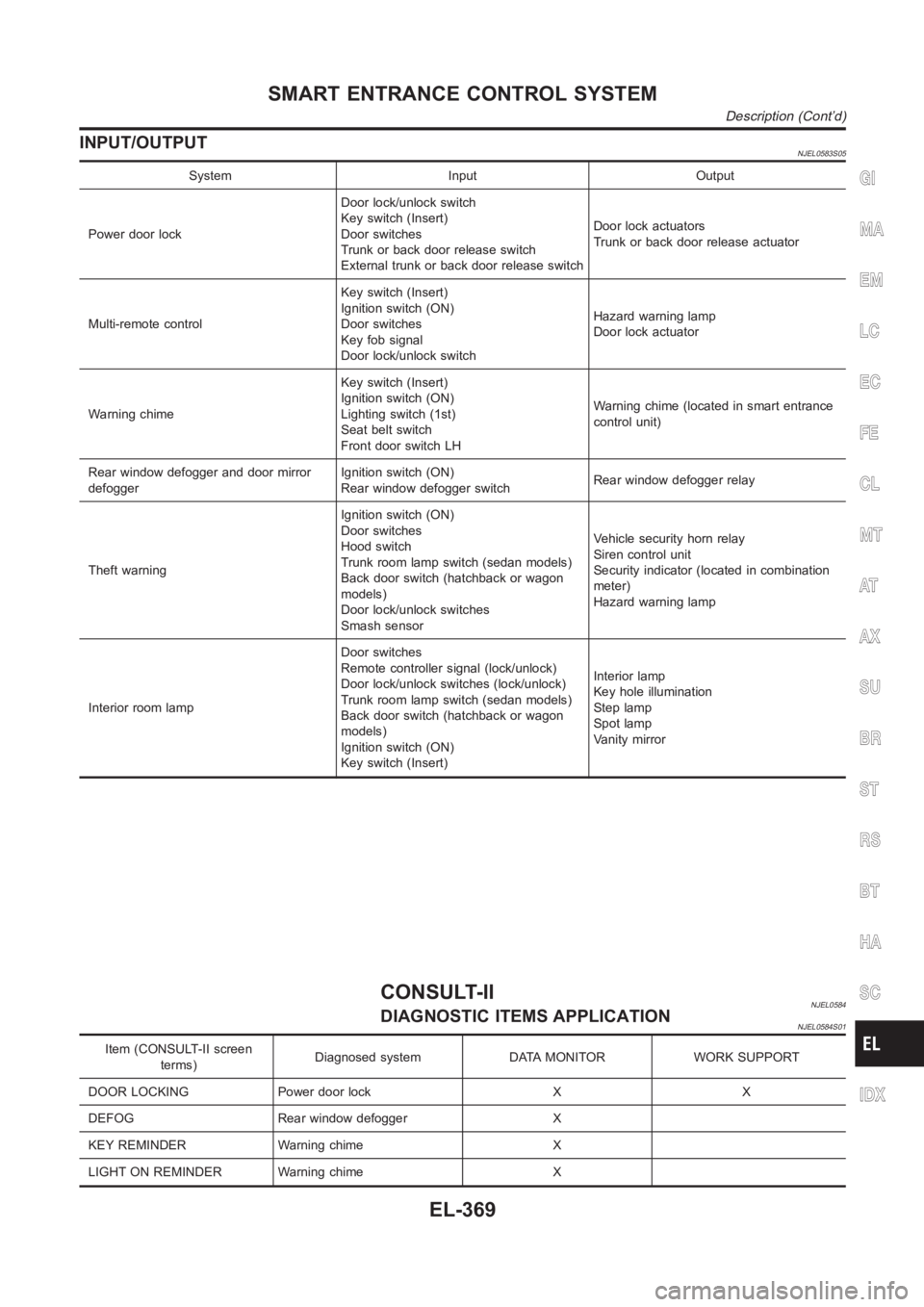
INPUT/OUTPUTNJEL0583S05
System Input Output
Power door lockDoor lock/unlock switch
Key switch (Insert)
Door switches
Trunk or back door release switch
External trunk or back door release switchDoor lock actuators
Trunk or back door release actuator
Multi-remote controlKey switch (Insert)
Ignition switch (ON)
Door switches
Key fob signal
Door lock/unlock switchHazard warning lamp
Door lock actuator
Warning chimeKey switch (Insert)
Ignition switch (ON)
Lighting switch (1st)
Seat belt switch
Front door switch LHWarning chime (located in smart entrance
control unit)
Rear window defogger and door mirror
defoggerIgnition switch (ON)
Rear window defogger switchRear window defogger relay
Theft warningIgnition switch (ON)
Door switches
Hood switch
Trunk room lamp switch (sedan models)
Back door switch (hatchback or wagon
models)
Door lock/unlock switches
Smash sensorVehicle security horn relay
Siren control unit
Security indicator (located in combination
meter)
Hazard warning lamp
Interior room lampDoor switches
Remote controller signal (lock/unlock)
Door lock/unlock switches (lock/unlock)
Trunk room lamp switch (sedan models)
Back door switch (hatchback or wagon
models)
Ignition switch (ON)
Key switch (Insert)Interior lamp
Key hole illumination
Step lamp
Spot lamp
Vanity mirror
CONSULT-IINJEL0584DIAGNOSTIC ITEMS APPLICATIONNJEL0584S01
Item (CONSULT-II screen
terms)Diagnosed system DATA MONITOR WORK SUPPORT
DOOR LOCKING Power door lock X X
DEFOG Rear window defogger X
KEY REMINDER Warning chime X
LIGHT ON REMINDER Warning chime X
GI
MA
EM
LC
EC
FE
CL
MT
AT
AX
SU
BR
ST
RS
BT
HA
SC
IDX
SMART ENTRANCE CONTROL SYSTEM
Description (Cont’d)
EL-369
Page 2713 of 3189
![NISSAN ALMERA N16 2003 Electronic Repair Manual Terminal
No.Wire
colorConnections Operated condition Voltage (Approximate values)
24 BRWasher switch
(Headlamp washer switch)[Head lamp switch 1st or 2nd posi-
tion]
Washer switch OFF,ON12V,0V
25 G/OR NISSAN ALMERA N16 2003 Electronic Repair Manual Terminal
No.Wire
colorConnections Operated condition Voltage (Approximate values)
24 BRWasher switch
(Headlamp washer switch)[Head lamp switch 1st or 2nd posi-
tion]
Washer switch OFF,ON12V,0V
25 G/OR](/manual-img/5/57350/w960_57350-2712.png)
Terminal
No.Wire
colorConnections Operated condition Voltage (Approximate values)
24 BRWasher switch
(Headlamp washer switch)[Head lamp switch 1st or 2nd posi-
tion]
Washer switch OFF,ON12V,0V
25 G/ORCombination switch
(Turn signal switch)Turn signal switch:
Neutral,Left turn position12V,0V
26 L/BCombination switch
(Turn signal switch)Turn signal switch:
Neutral,Right turn position12V,0V
27 Y/BVehicle security horn relay
(RHD models)When theft warning system:
Armed,Disarmed0V,12V
28 R/Y Interior room lampWhen interior lamp is operated using
remote controller (Lamp switch in
“DOOR” position)12V,0V
29 Y/G Ignition key switch Ignition key is in “ON” position 12V
30 G/R Hazard switch Hazard switch: OFF,ON 12V,0V
31 W Rear window defogger relay[Ignition switch “ON”]
Rear window defogger switch:
OFF,ON12V,0V
32 LG/B Cooling fan relay[Ignition switch“ ON”]
Cooling fan: Operating,Not operat-
ing0V,12V
33 LG/R Cooling fan relay[Ignition switch “ON”]
Cooling fan: Operating,Not operat-
ing0V,12V
34 L/Y Security indicator Ignition switch ON,OFF 12V,0V
39 BR/WRear door switch
(Passenger side)Rear door LH or RH: Open,Closed 0V,12V
41 L Air conditioner relay[Engine is running]
Air conditioner switch: ON,
OFF12V,0V
43 R/WFront door switch
(Driver side)Front door (Driver side):
Open,Closed12V,0V
44 R/WFront door switch
(Passenger side)Front door (Passenger side):
Open,Closed0V,12V
45 R/YRear door switch
(Driver side)Rear door LH or RH: Open,Closed 0V,12V
49 W/L Power source — 12V
50 GPower door super lock actuator
(Rear)Remote controller door lock switch:
Free,Press0V,12V
51 L/R Driver door lock actuatorDoor lock & unlock switch:
Free,Lock0V,12V
52 W/R Door lock actuatorsDoor lock & unlock switch:
Free,Unlock0V,12V
53 B Ground — 0V
54 R/B Door lock actuatorsDoor lock & unlock switch:
Free,Unlock0V,12V
55 W/BPower door super lock actuator
(Front)Remote controller door lock switch:
Free,Unlock0V,12V
56 R/B Power source — 12V
GI
MA
EM
LC
EC
FE
CL
MT
AT
AX
SU
BR
ST
RS
BT
HA
SC
IDX
SMART ENTRANCE CONTROL SYSTEM
Smart Entrance Control Unit Inspection Table (Cont’d)
EL-377
Page 2717 of 3189
Description=NJEL0485The TCU is applied for YD engine models without common rail and K9K engine models.
The TCU has the following functions.
INTERIOR LAMP TIMERNJEL0485S01The interior lamp timer is controlled by the TCU.
For further information, refer to “INTERIOR ROOM LAMP” (EL-80).
IGNITION KEY WARNING CHIME AND LIGHT WARNING CHIMENJEL0485S02The ignition key and light warning chime are controlled by the TCU.
For further information, refer to “WARNING CHIME” (EL-136).
REAR WINDOW DEFOGGER TIMERNJEL0485S03The rear window defogger and door mirror defogger system are controlled bythe TCU.
For further information, refer to “REAR WINDOW DEFOGGER” (EL-174).
POWER DOOR LOCK (SUPER LOCK)NJEL0485S04The power door lock (super lock) is controlled by the TCU.
For further information, refer to “POWER DOOR LOCK — Super Lock —” (EL-301).
MULTI-REMOTE CONTROL SYSTEMNJEL0485S05The multi-remote control system is controlled by the TCU.
For further information, refer to “MULTI-REMOTE CONTROL SYSTEM” (EL-352).
FUNCTIONNJEL0485S06The TCU has the following control function.
Item Details of control
Direction indicatorsSwitches the director indicators (Left, Right or All) when the combination
switch or hazard switch is operated.
Light warning chimeSounds warning chime when driver’s door is opened with light switch in the
1st or 2nd position and ignition switch “OFF”.
Ignition key warning chineSounds warning chime when driver’s door is opened with key in ignition and
the driver door lock knob (unlock sensor) is moved from the “unlock” posi-
tion to the “lock” position.
Rear window defogger timerTurn off rear window defogger and door mirror heater, if equipped, about 15
minutes after the rear window defogger switch is turned “ON”.
Battery saverShuts off interior lamp in 30 minutes if any door is left open when ignition
switch is “OFF”. The battery saver will reset if ignition switch is cycled or any
door is opened or closed.
Interior lamp timerKeep interior lamp illuminated for about 30 seconds when:
driver’s door is unlocked,
the ignition is switched off,
driver’s door is opened and then closed.
The timer is cancelled, and interior lamp turns off when:
driver’s door is locked, or
ignition switch is turned “ON”.
Power door lock Centrally locks and unlocks the vehicle
Super lock Activates and de-activates the super lock system.
GI
MA
EM
LC
EC
FE
CL
MT
AT
AX
SU
BR
ST
RS
BT
HA
SC
IDX
TIME CONTROL UNIT
Description
EL-381