2003 NISSAN ALMERA N16 combination switch
[x] Cancel search: combination switchPage 2404 of 3189
hatchback models).
With power and ground supplied, the smart entrance control unit controls the flashing of the RH turn signal
lamps, and smart entrance control unit sent RH turn signal to combination meter with CAN communication
line.
to combination meter terminal 26 and 27
from smart entrance control unit terminal 8 and 11.
HAZARD LAMP OPERATIONNJEL0430S02Power is supplied at all times
through 15A fuse [No. 5, located in fuse block (J/B)]
to smart entrance control unit terminal 56
With the hazard switch in the ON position, ground is supplied from body grounds F118 (QG engine models),
M28 and M67 to
smart entrance control unit terminal 30
through hazard switch terminals 1 and 3
With ground is supplied, smart entrance control unit controls the flashing of the hazard warning lamps.
Power is supplied from smart entrance control unit terminal 64
to front turn signal lamp LH terminal 1,
to side turn signal lamp LH terminal 2,
to rear combination lamp LH terminal 2 (for sedan models) or
to rear combination lamp LH terminal 5 (for hatchback models).
Power is supplied from smart entrance control unit terminal 63
to front turn signal lamp RH terminal 1,
to side turn signal lamp RH terminal 2,
to rear combination lamp RH terminal 2 (for sedan models) or
to rear combination lamp RH terminal 5 (for hatchback models).
Ground is supplied to terminal 2 each front turn signal lamp through body grounds E30 and E73.
Ground is supplied to terminal 1 each side turn signal lamp through body grounds E30 and E73.
Ground is supplied to terminal 1 of rear combination lamp through body grounds B9 and B21 and B308 (for
sedan models).
Ground is supplied to terminal 4 of rear combination lamp through body grounds B9, B21 and D96 (for hatch-
back models).
With power and ground supplied, the smart entrance control unit controls the flashing of the hazard warning
lamps, and smart entrance control unit sent flashing indicator signal (hazard warning signal) to combination
meter with CAN communication line.
to combination meter terminal 26 and 27
from smart entrance control unit terminals 8 and 11.
HAZARD REMINDER OPERATION FOR MULTI-REMOTE CONTROL SYSTEMNJEL0430S04When the doors are locked or unlocked by multi-remote controller, smart entrance control unit controls turn
lamps hazard reminder flashes as follows.
Locked operation: Flash once
Unlock operation: Flash twice
TURN SIGNAL AND HAZARD WARNING LAMPS
System Description/QG Engine Models and YD Engine Models with Common Rail(Cont’d)
EL-68
Page 2410 of 3189
Trouble DiagnosesNJEL0432
Symptom Possible cause Repair order
Turn signal and hazard warning
lamps do not operate.1. Smart entrance control unit
2. Smart entrance control unit cir-
cuit1. Check power door lock operation.
2. Check power supply and ground circuit for time con-
trol unit.
Turn signal lamps do not operate
but hazard warning lamps operate.1. Turn signal switch
2. Open in turn signal switch cir-
cuit1. Check turn signal switch.
2. Check turn signal switch ground for open circuit.
Hazard warning lamps do not
operate but turn signal lamps
operate.1. Hazard switch
2. Open in hazard switch circuit1. Check hazard switch.
2. Check hazard switch ground for open circuit.
Front turn signal lamp LH or RH
does not operate.1. Bulb
2. Open in front turn signal lamp
circuit1. Check bulb.
2. Check power supply and ground circuit for front turn
signal lamp.
Side turn signal lamp LH or RH
does not operate.1. Bulb
2. Open in rear combination lamp
circuit1. Check bulb.
2. Check power supply and ground circuit for rear com-
bination lamp.
Rear combination lamp LH or RH
does not operate.1. Bulb
2. Open in side turn signal lamp
circuit1. Check bulb.
2. Check grounds check power supply and ground circuit
for rear combination lamp.
LH and RH turn indicators do not
operate.1. Ground
2. CAN communication line1. Check grounds E30 and E73
2. Perform self-diagnosis for smart entrance control unit
If self-diagnosis result is OK, replace combination
meter
If self-diagnosis result is NG, refer to EL-380, “CAN
Communication Line Check”.
LH or RH turn indicator does not
operate.1. Bulb 1. Check bulb in combination meter.
TURN SIGNAL AND HAZARD WARNING LAMPS
Trouble Diagnoses
EL-74
Page 2416 of 3189
![NISSAN ALMERA N16 2003 Electronic Repair Manual System Description/QG and YD Engine Models
with Common Rail
=NJEL0435POWER SUPPLY AND GROUNDNJEL0435S01Power is supplied at all times:
through 10A fuse [No. 12, located in the fuse block (J/B)]
to sma NISSAN ALMERA N16 2003 Electronic Repair Manual System Description/QG and YD Engine Models
with Common Rail
=NJEL0435POWER SUPPLY AND GROUNDNJEL0435S01Power is supplied at all times:
through 10A fuse [No. 12, located in the fuse block (J/B)]
to sma](/manual-img/5/57350/w960_57350-2415.png)
System Description/QG and YD Engine Models
with Common Rail
=NJEL0435POWER SUPPLY AND GROUNDNJEL0435S01Power is supplied at all times:
through 10A fuse [No. 12, located in the fuse block (J/B)]
to smart entrance control unit terminal 56
to key switch terminal 1 and
through 10A fuse [No. 13, located in the fuse block (J/B)]
to interior room lamp terminal 1.
When the key is removed from ignition key cylinder, power is interrupted:
through key switch terminal 2
to smart entrance control unit terminal 5.
With the ignition key switch in the ON or START position, power is supplied:
through 10A fuse [No. 10, located in the fuse block (J/B)]
to smart entrance control unit terminal 29.
Ground is supplied:
through body grounds terminals F118 (QG engine models), M28 and M67
to smart entrance control unit terminal 53
When the driver side door is opened, ground is supplied:
through body grounds B9, B21 and D96 (Hatchback) or B308 (Sedan)
to door switch driver side terminal 3
from door switch driver side terminal 2
to smart entrance control unit terminal 43.
When any door is opened, ground is supplied:
through case ground of each door switch
to each door switch terminal 1
to smart entrance control unit terminal 44.
When the driver side door is unlocked by the door lock/unlock switch, the smart entrance control unit receives
a ground signal:
through body grounds M28, M67 and F118 (QG engine models)
to door lock/unlock switch terminal 3
from door lock/unlock switch terminal 7 (with power window system) or
from door lock/unlock switch terminal 2 (without power window system)
to smart entrance control unit terminal 14.
When the driver side door is locked by the door lock/unlock switch, the smart entrance control unit receives
a ground signal:
through body grounds M28, M67 and F118 (QG engine models)
to door lock/unlock switch terminal 3
from door lock/unlock switch terminal 14 (with power window system) or
from door lock/unlock switch terminal 1 (without power window system)
to smart entrance control unit terminal 13.
When a signal, or combination of signals is received by the smart entrance control unit, ground is supplied:
through smart entrance control unit terminal 28
to interior room lamp terminal 5.
With power and ground supplied, the interior room lamp illuminates when interior room lamp switch is in
“DOOR” position.
SWITCH OPERATIONNJEL0435S02When interior room lamp switch is in “ON” position, ground is supplied:
through case grounds of interior room lamp
to interior room lamp.
With power and ground supplied, the interior room lamp illuminates.
INTERIOR ROOM LAMP
System Description/QG and YD Engine Models with Common Rail
EL-80
Page 2418 of 3189
System Description/YD Engine Models without
Common Rail and K9K Engine Models
=NJEL0548POWER SUPPLY AND GROUNDNJEL0548S01Power is supplied at all times:
through 15A fuse [No. 5, located in the fuse block (J/B)]
to time control unit terminal 9,
through 10A fuse [No. 12, located in the fuse block (J/B)]
to key switch terminal 1 and
through 10A fuse [No. 13, located in the fuse block (J/B)]
to interior room lamp terminal 1.
When the key is removed from ignition key cylinder, power is interrupted:
through key switch terminal 2
to time control unit terminal 22.
With the ignition key switch in the ON or START position, power is supplied:
through 10A fuse [No. 10, located in the fuse block (J/B)]
to time control unit terminal 1.
Ground is supplied:
through body grounds terminals M28 and M67
to time control unit terminal 16
When the driver side door is opened, ground is supplied:
through body grounds B9, B21 and D96 (Hatchback) or B308 (Sedan)
to door switch driver side terminal 3
from door switch driver side terminal 2
to time control unit terminal 6.
When any door is opened, ground is supplied:
through case ground of each door switch
to each door switch terminal 1
to time control unit terminal 7.
When the driver side door is unlocked, the time control unit receives a ground signal:
through body grounds terminals M28 and M67
to door unlock sensor terminal 2 (RHD models) or 4 (LHD models)
from door unlock sensor terminal 5 (RHD models) or 2 (LHD models)
to time control unit terminal 35.
When a signal, or combination of signals is received by the time control unit, ground is supplied:
through time control unit terminal 12
to interior room lamp terminal 2.
With power and ground supplied, the interior room lamp illuminates when interior room lamp switch is in
“DOOR” position.
SWITCH OPERATIONNJEL0548S02When interior room lamp switch is in “ON” position, ground is supplied:
through case grounds of interior room lamp
to interior room lamp.
With power and ground supplied, the interior room lamp illuminates.
INTERIOR ROOM LAMP TIMER OPERATIONNJEL0548S03When interior room lamp switch is in the “DOOR” position, the time control unit keeps the interior room lamp
illuminated for about 30 seconds when:
unlock signal is supplied from driver’s door unlock sensor while all doorsare closed
key is removed from ignition key cylinder while all doors are closed
driver’s door is opened and then closed
The timer is canceled when:
INTERIOR ROOM LAMP
System Description/YD Engine Models without Common Rail and K9K Engine Models
EL-82
Page 2446 of 3189
Component Parts and Harness Connector
Location
NJEL0441For details, refer to “ELECTRICAL UNIT LOCATION” (EL-543) and
“HARNESS LAYOUT” (EL-550).
System DescriptionNJEL0442UNIFIED CONTROL METERNJEL0442S01Speedometer, odo/trip meter, tachometer, fuel gauge and water temperature gauge are controlled totally
by control unit built-in combination meter.
Digital meter is adopted for odo/trip meter.*
*The record of the odo meter is kept even if the battery cable is disconnected. The record of the trip meter
is erased when the battery cable is disconnected.
Odo/trip meter segment can be checked in diagnosis mode.
Meter/gauge can be checked in diagnosis mode.
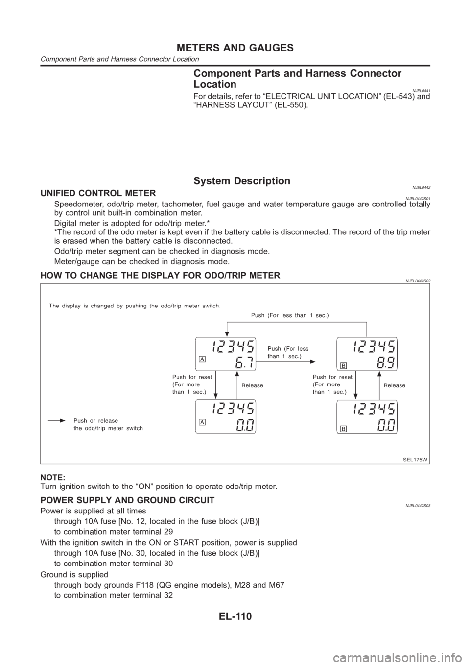
HOW TO CHANGE THE DISPLAY FOR ODO/TRIP METERNJEL0442S02
SEL175W
NOTE:
Turn ignition switch to the “ON” position to operate odo/trip meter.
POWER SUPPLY AND GROUND CIRCUITNJEL0442S03Power is supplied at all times
through 10A fuse [No. 12, located in the fuse block (J/B)]
to combination meter terminal 29
With the ignition switch in the ON or START position, power is supplied
through 10A fuse [No. 30, located in the fuse block (J/B)]
to combination meter terminal 30
Ground is supplied
through body grounds F118 (QG engine models), M28 and M67
to combination meter terminal 32
METERS AND GAUGES
Component Parts and Harness Connector Location
EL-110
Page 2453 of 3189
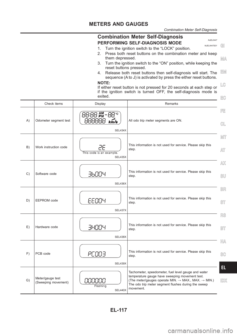
Combination Meter Self-DiagnosisNJEL0447PERFORMING SELF-DIAGNOSIS MODENJEL0447S011. Turn the ignition switch to the “LOCK” position.
2. Press both reset buttons on the combination meter and keep
them depressed.
3. Turn the ignition switch to the “ON” position, while keeping the
reset buttons pressed.
4. Release both reset buttons then self-diagnosis will start. The
sequence (A to J) is activated by press the either reset buttons.
NOTE:
If either reset button is not pressed for 20 seconds at each step or
if the ignition switch is turned OFF, the self-diagnosis mode is
exited.
Check items Display Remarks
A) Odometer segment test
SEL434X
All odo trip meter segments are ON.
B) Work instruction code
SEL435X
This information is not used for service. Please skip this
step.
C) Software code
SEL436X
This information is not used for service. Please skip this
step.
D) EEPROM code
SEL437X
This information is not used for service. Please skip this
step.
E) Hardware code
SEL438X
This information is not used for service. Please skip this
step.
F) PCB code
SEL439X
This information is not used for service. Please skip this
step.
G)Meter/gauge test
(Sweeping movement)
SEL440X
Tachometer, speedometer, fuel level gauge and water
temperature gauge have sweeping movement test.
(The meter/gauges operate MIN.,MAX., MAX.,MIN.)
The odo trip meter segment flushes during the sweep
movement.
GI
MA
EM
LC
EC
FE
CL
MT
AT
AX
SU
BR
ST
RS
BT
HA
SC
IDX
METERS AND GAUGES
Combination Meter Self-Diagnosis
EL-117
Page 2458 of 3189
YEL813D
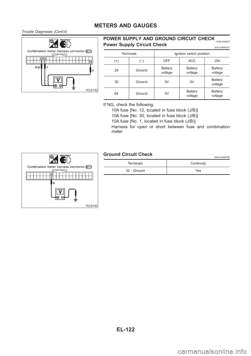
POWER SUPPLY AND GROUND CIRCUIT CHECK=NJEL0448S03Power Supply Circuit CheckNJEL0448S0301
Terminals Ignition switch position
(+) (−) OFF ACC ON
29 GroundBattery
voltageBattery
voltageBattery
voltage
30 Ground 0V 0VBattery
voltage
64 Ground 0VBattery
voltageBattery
voltage
If NG, check the following.
10A fuse [No. 12, located in fuse block (J/B)]
10A fuse [No. 30, located in fuse block (J/B)]
10A fuse [No. 1, located in fuse block (J/B)]
Harness for open or short between fuse and combination
meter
YEL814D
Ground Circuit CheckNJEL0448S0302
Terminals Continuity
32 - Ground Yes
METERS AND GAUGES
Trouble Diagnoses (Cont’d)
EL-122
Page 2471 of 3189
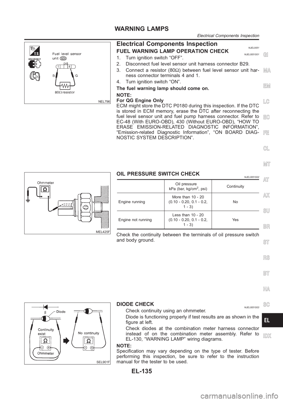
NEL796
Electrical Components InspectionNJEL0051FUEL WARNING LAMP OPERATION CHECKNJEL0051S011. Turn ignition switch “OFF”.
2. Disconnect fuel level sensor unit harness connector B29.
3. Connect a resistor (80Ω) between fuel level sensor unit har-
ness connector terminals 4 and 1.
4. Turn ignition switch “ON”.
The fuel warning lamp should come on.
NOTE:
For QG Engine Only
ECM might store the DTC P0180 during this inspection. If the DTC
is stored in ECM memory, erase the DTC after reconnecting the
fuel level sensor unit and fuel pump harness connector. Refer to
EC-48 (With EURO-OBD), 430 (Without EURO-OBD), “HOW TO
ERASE EMISSION-RELATED DIAGNOSTIC INFORMATION”,
“Emission-related Diagnostic Information”, “ON BOARD DIAG-
NOSTIC SYSTEM DESCRIPTION”.
MEL425F
OIL PRESSURE SWITCH CHECKNJEL0051S02
Oil pressure
kPa (bar, kg/cm2, psi)Continuity
Engine runningMore than 10 - 20
(0.10 - 0.20, 0.1 - 0.2,
1-3)No
Engine not runningLess than 10 - 20
(0.10 - 0.20, 0.1 - 0.2,
1-3)Ye s
Check the continuity between the terminals of oil pressure switch
and body ground.
SEL901F
DIODE CHECKNJEL0051S03Check continuity using an ohmmeter.
Diode is functioning properly if test results are as shown in the
figure at left.
Check diodes at the combination meter harness connector
instead of on the combination meter assembly. Refer to
EL-130, “WARNING LAMP” wiring diagrams.
NOTE:
Specification may vary depending on the type of tester. Before
performing this inspection, be sure to refer to the instruction
manual for the tester to be used.
GI
MA
EM
LC
EC
FE
CL
MT
AT
AX
SU
BR
ST
RS
BT
HA
SC
IDX
WARNING LAMPS
Electrical Components Inspection
EL-135