Page 2847 of 3189
TYPE 2=NJEL0536S02System DiagramNJEL0536S0201
SEL826Y
Input/Output Signal ChartNJEL0536S0202T: Transmit R: Receive
Signals ECMSmart entrance control
unitCombination meter
Engine speed signal T R
Rear window defogger signal R T
Heater fan switch signal R T
Air conditioner switch signal R T
MI signal T R
Engine coolant temperature signal T R
Fuel consumption signal T R
Vehicle speed signal R T
Seat belt reminder signal R T
Headlamp switch signal T R
Flashing indicator signal T R
Engine cooling fan speed signal T R
Child lock indicator signal T R
Door switches state signal T R
A/C compressor signal T R
GI
MA
EM
LC
EC
FE
CL
MT
AT
AX
SU
BR
ST
RS
BT
HA
SC
IDX
CAN COMMUNICATION
CAN Communication Unit (Cont’d)
EL-511
Page 2861 of 3189

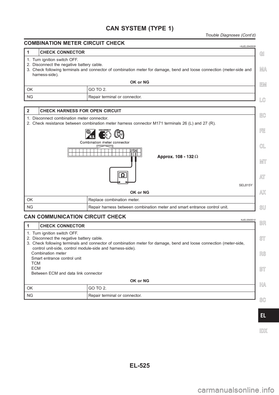
COMBINATION METER CIRCUIT CHECK=NJEL0540S09
1 CHECK CONNECTOR
1. Turn ignition switch OFF.
2. Disconnect the negative battery cable.
3. Check following terminals and connector of combination meter for damage, bend and loose connection (meter-side and
harness-side).
OK or NG
OK GO TO 2.
NG Repair terminal or connector.
2 CHECK HARNESS FOR OPEN CIRCUIT
1. Disconnect combination meter connector.
2. Check resistance between combination meter harness connector M171 terminals 26 (L) and 27 (R).
SEL815Y
OK or NG
OK Replace combination meter.
NG Repair harness between combination meter and smart entrance control unit.
CAN COMMUNICATION CIRCUIT CHECKNJEL0540S10
1 CHECK CONNECTOR
1. Turn ignition switch OFF.
2. Disconnect the negative battery cable.
3. Check following terminals and connector of combination meter for damage, bend and loose connection (meter-side,
control unit-side, control module-side and harness-side).
Combination meter
Smart entrance control unit
TCM
ECM
Between ECM and data link connector
OK or NG
OK GO TO 2.
NG Repair terminal or connector.
GI
MA
EM
LC
EC
FE
CL
MT
AT
AX
SU
BR
ST
RS
BT
HA
SC
IDX
CAN SYSTEM (TYPE 1)
Trouble Diagnoses (Cont’d)
EL-525
Page 2874 of 3189
COMBINATION METER CIRCUIT CHECK=NJEL0545S07
1 CHECK CONNECTOR
1. Turn ignition switch OFF.
2. Disconnect the negative battery cable.
3. Check terminals and connector of combination meter for damage, bend andloose connection (meter-side and harness-
side).
OK or NG
OK GO TO 2.
NG Repair terminal or connector.
2 CHECK HARNESS FOR OPEN CIRCUIT
1. Disconnect combination meter connector.
2. Check resistance between combination meter harness connector M171 terminals 26 (L) and 27 (R).
SEL815Y
OK or NG
OK Replace combination meter.
NG Repair harness between combination meter and smart entrance control unit.
CAN SYSTEM (TYPE 2)
Trouble Diagnoses (Cont’d)
EL-538
Page 2875 of 3189

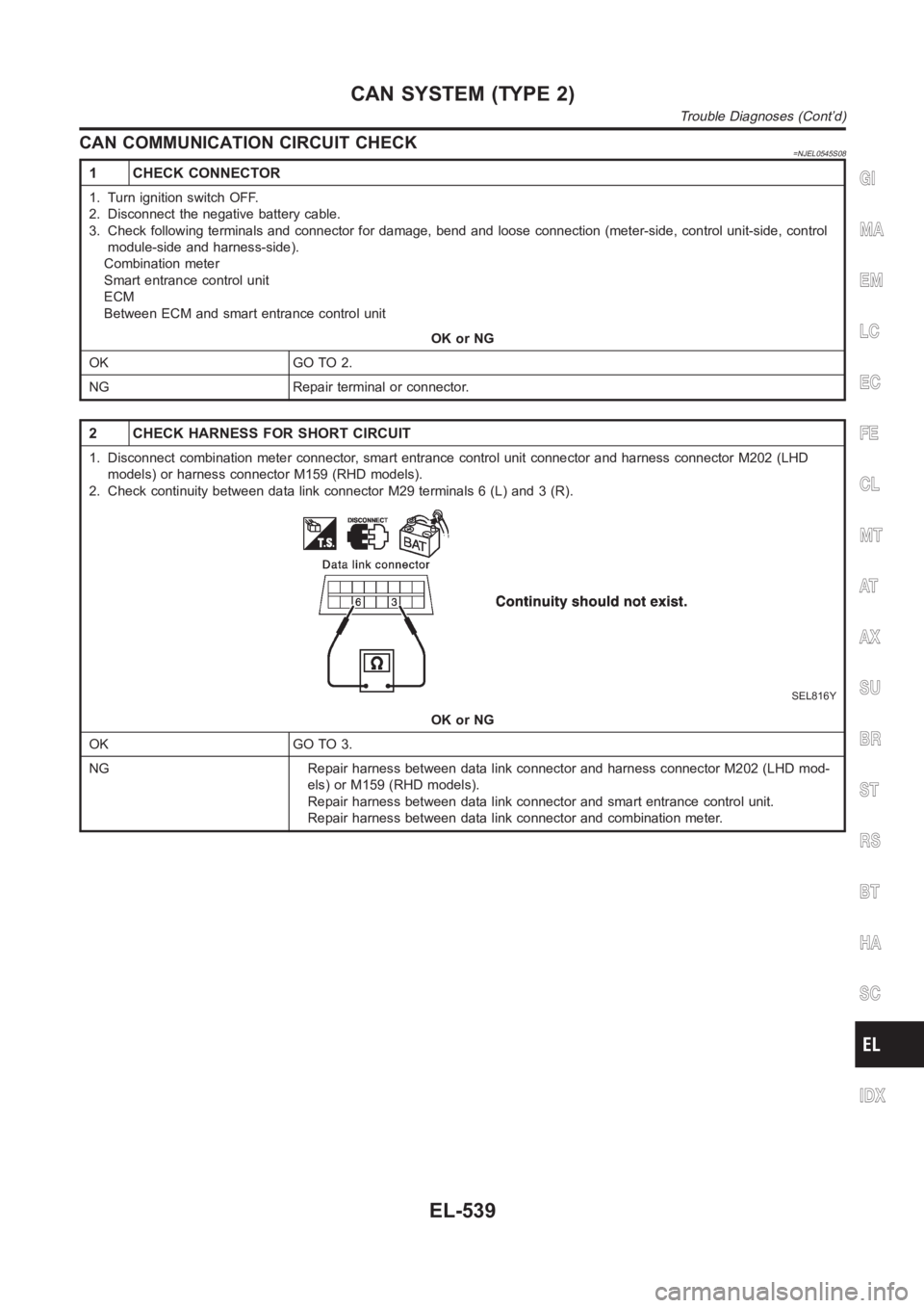
CAN COMMUNICATION CIRCUIT CHECK=NJEL0545S08
1 CHECK CONNECTOR
1. Turn ignition switch OFF.
2. Disconnect the negative battery cable.
3. Check following terminals and connector for damage, bend and loose connection (meter-side, control unit-side, control
module-side and harness-side).
Combination meter
Smart entrance control unit
ECM
Between ECM and smart entrance control unit
OK or NG
OK GO TO 2.
NG Repair terminal or connector.
2 CHECK HARNESS FOR SHORT CIRCUIT
1. Disconnect combination meter connector, smart entrance control unit connector and harness connector M202 (LHD
models) or harness connector M159 (RHD models).
2. Check continuity between data link connector M29 terminals 6 (L) and 3 (R).
SEL816Y
OK or NG
OK GO TO 3.
NG Repair harness between data link connector and harness connector M202 (LHD mod-
els) or M159 (RHD models).
Repair harness between data link connector and smart entrance control unit.
Repair harness between data link connector and combination meter.
GI
MA
EM
LC
EC
FE
CL
MT
AT
AX
SU
BR
ST
RS
BT
HA
SC
IDX
CAN SYSTEM (TYPE 2)
Trouble Diagnoses (Cont’d)
EL-539
Page 2992 of 3189
8 CHECK VOLTAGE FOR COMBINATION METER (FAN ON SIGNAL)
Do approx. 12 volts exist between combination meter harness terminal No. 45 and body ground?
RHA259I
YesorNo
Yes QG engine: GO TO 9.
YD engine: GO TO 10.
No Check combination meter. Refer to EL-110.
9 CHECK REFRIGERANT PRESSURE SENSOR
Refer to HA-65.
OK or NG
OK GO TO 10.
NG Replace refrigerant pressure sensor.
10 CHECK A/C SWITCH
Refer to HA-65.
OK or NG
OK GO TO 11.
NG Replace heater control panel.
11 CHECK POWER SUPPLY FOR HEATER CONTROL PANEL (A/C SWITCH)
Do approx. 12 volts exist between heater control panel harness terminal No. 7 and body ground?
RHA260I
YesorNo
Yes GO TO 16.
No QG engine: GO TO 12.
YD engine: GO TO 13.
TROUBLE DIAGNOSESMANUAL
Magnet Clutch (Cont’d)
HA-56
Page 2993 of 3189
12 CHECK CIRCUIT CONTINUITY BETWEEN HEATER CONTROL PANEL AND COMBINATIONMETER
Check circuit continuity between heater control panel harness terminal No. 7 and combination meter harness terminal No.
39.
RHA261I
Continuity should exist.
If OK, check harness for short.
OK or NG
OK Check combination meter. Refer to EL-110.
NG Repair harness or connector.
13 CHECK CIRCUIT CONTINUITY BETWEEN DUAL-PRESSURE SWITCH AND COMBINATION METER
Check circuit continuity between dual-pressure switch harness terminalNo. 2 and combination meter harness terminal No.
39.
RHA262I
Continuity should exist.
If OK, check harness for short.
OK or NG
OK GO TO 14.
NG Repair harness or connector.
14 CHECK DUAL-PRESSURE SWITCH
Refer to HA-65.
OK or NG
OK GO TO 15.
NG Repair dual-pressure switch.
GI
MA
EM
LC
EC
FE
CL
MT
AT
AX
SU
BR
ST
RS
BT
SC
EL
IDX
TROUBLE DIAGNOSESMANUAL
Magnet Clutch (Cont’d)
HA-57
Page 2994 of 3189
15 CHECK CIRCUIT CONTINUITY BETWEEN DUAL-PRESSURE SWITCH AND HEATER CONTROL PANEL
Check circuit continuity between dual-pressure switch harness terminalNo. 1 and heater control panel harness terminal
No. 7.
RHA263I
Continuity should exist.
If OK, check harness for short.
OK or NG
OK Check combination meter. Refer to EL-110.
NG Repair harness or connector.
16 CHECK HEATER CONTROL PANEL CIRCUIT
Check circuit continuity between heater control panel harness terminal No. 8 and 18.
RHA267I
Continuity should exist.
If OK, check harness for short.
OK or NG
OK GO TO 17.
NG Repair harness or connector.
TROUBLE DIAGNOSESMANUAL
Magnet Clutch (Cont’d)
HA-58
Page 2995 of 3189
17 CHECK CIRCUIT CONTINUITY BETWEEN COMBINATION METER AND HEATER CONTROLPANEL
Check circuit continuity between combination meter harness terminal No.45 and heater control panel harness terminal No.
18.
RHA265I
Continuity should exist.
If OK, check harness for short.
OK or NG
OK GO TO 18.
NG Repair harness or connector.
18 CHECK FAN SWITCH
Refer to HA-51.
YesorNo
Yes GO TO 19.
No Replace heater control panel.
19 CHECK BODY GROUND CIRCUIT
Check circuit continuity between heater control panel harness terminal No. 13 and body ground.
NHA506
Continuity should exist.
If OK, check harness for short.
OK or NG
OK GO TO 20.
NG Repair harness or connector.
GI
MA
EM
LC
EC
FE
CL
MT
AT
AX
SU
BR
ST
RS
BT
SC
EL
IDX
TROUBLE DIAGNOSESMANUAL
Magnet Clutch (Cont’d)
HA-59